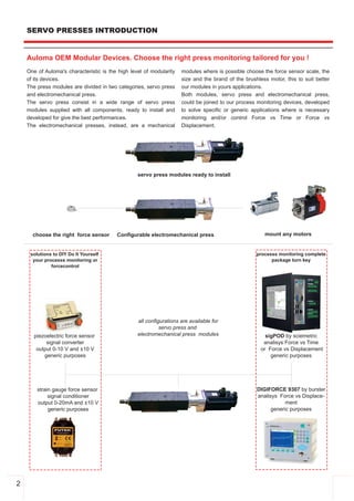
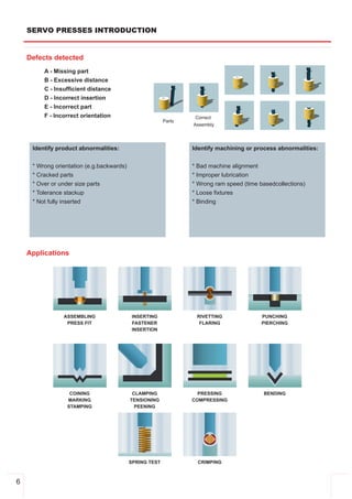
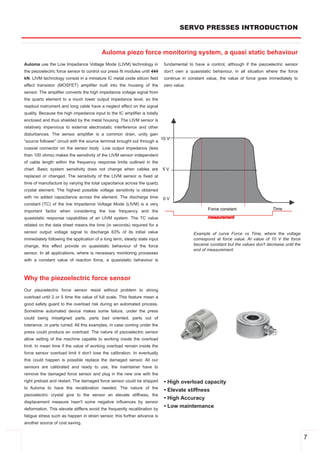
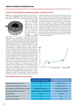
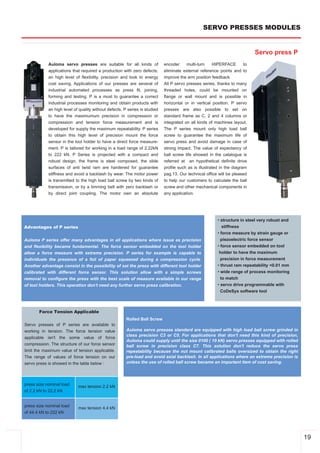
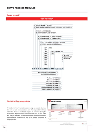
Downloaded 17 times

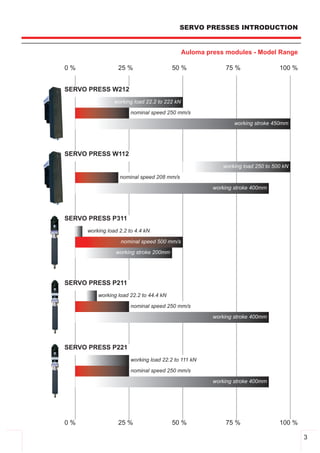
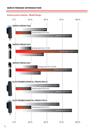
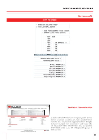
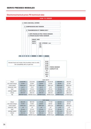
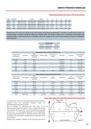
![SERVO PRESSES MODULES
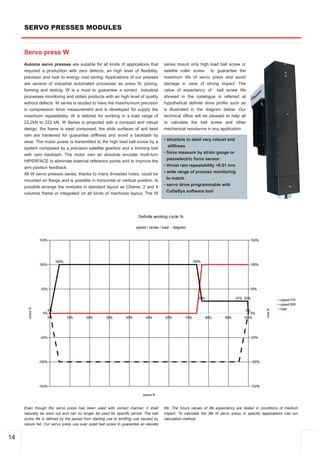
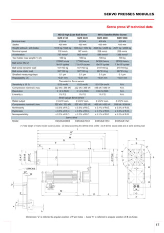
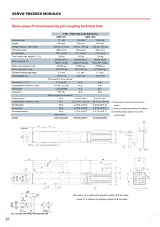
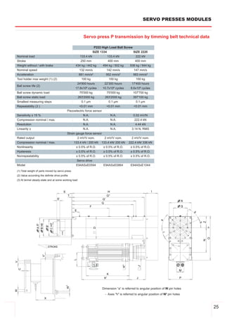
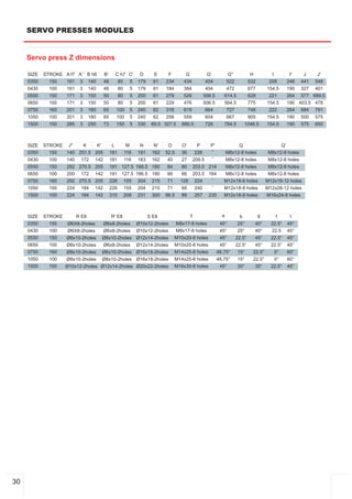
Servo drive features
servo drive E94ASxE
Size 0134 0174 0324 0594 0864 1044 1454 1724 2024
Mains voltage range 3/PE AC 180 V 0 % … 550 V +0 %; 45 Hz 0 % … 65 Hz +0 %
Rated output current [A] 16.5 23.5 32 59 86 104 145 172 202
Rated switching frequency [kHz] 8 8 8 4 4 4 4 4 4
Max. output current 1) [A] 49.5 58.8 76,8 118 172 208 261 310 364
Typical motor power [kW] 7.5 11 15 30 45 55 75 90 105
Electronics supply Internal; alternatively DC 24 V external
Brake chopper Integrated
Brake resistor External
Dimensions (H x W x D) [mm] 481 x 60 x 288 602 x 206 x 294 702 x 266 x 370 930x407x427 1199 x 407 x 427
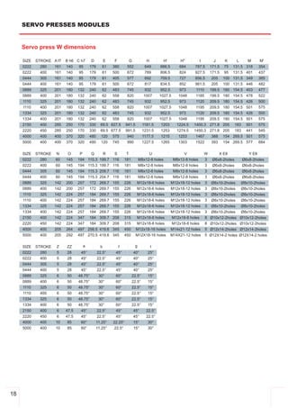
A B
C
size a b b1 b2 e c1 d g m kg
0134 120 8
A
0174 120 8
0324 206 606 556 630 294 170 585 6.5 12.5 26.5
0594 206 606 556 630 294 170 585 6.5 12.5 26.5
B
0864 266 706 655 729 370 230 685 6.5 12.5 42
1044 266 706 655 729 370 230 685 6.5 12.5 42
1454 930 897 885 95
1724 1199 1166 1154 107 C
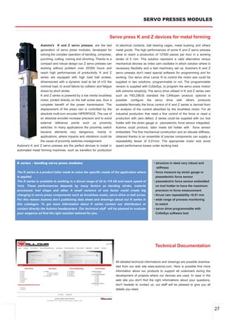
2024 1199 1166 1154 109
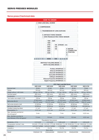
mm
12](https://image.slidesharecdn.com/main-catalogue-121013023754-phpapp02/85/Servo-press-auloma-catalogue-14-320.jpg)
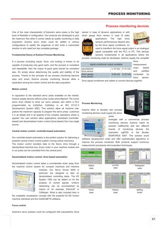


The document provides an overview of Auloma's OEM modular devices for press monitoring, detailing various models of servo and electromechanical presses, their specifications, and functionalities. It emphasizes the importance of selecting the appropriate force sensor, highlighting the differences between piezoelectric and strain gauge sensors for specific applications. Additionally, the document discusses the integration of motion control and process monitoring systems to optimize production quality and efficiency in manufacturing environments.