Download to read offline
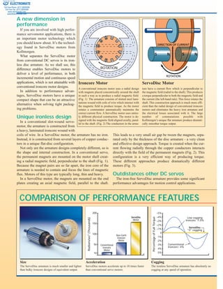
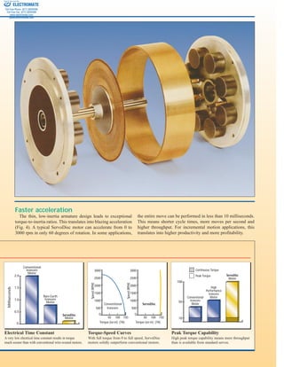
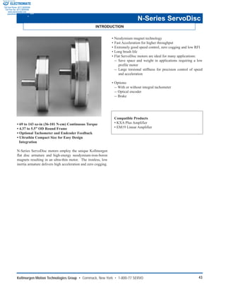

The document describes ServoDisc motors from Kollmorgen that offer improved performance over conventional DC servo motors for motion control applications. Key points: 1) ServoDisc motors use an ironless copper disc armature and axial magnetic field, enabling up to 10 times faster acceleration and zero cogging torque compared to conventional designs. 2) Their compact, low-inertia design provides full torque from zero to maximum speed, outperforming conventional motors for applications requiring high throughput. 3) The catalog presents specifications for Kollmorgen's N-Series ServoDisc motors, ranging from 69 to 143 oz-in of continuous torque, with optional feedback devices and compatible amplifiers.


