Download as PDF, PPTX


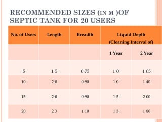
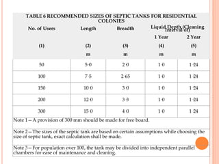


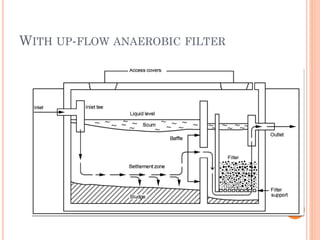


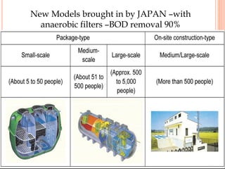


This document provides information on septic tank design and construction according to Indian standard IS 2470 (Part 1) - 1985. It discusses topics such as septic tank components, sizing calculations based on user population, construction materials, inlet and outlet design, and advanced treatment systems for septic tank effluent. The key points covered are: septic tanks provide preliminary treatment of sewage through sedimentation and anaerobic digestion; sizing is based on detention time, liquid capacity and partitioning for larger tanks; construction requires waterproof materials and access points for cleaning; and advanced filters can achieve higher removals of BOD compared to conventional septic tank systems.