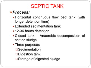
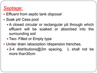
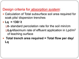
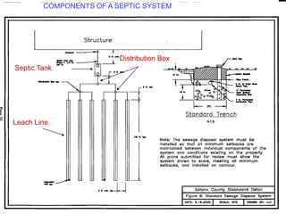
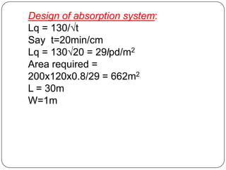
OTHER TREATMENT
          PROCESSES
Other processes include:
 Septic tank
 Imhoff tank
 Ponds
 Lagoons
 Ditches
TREAT SEWAGE SO THAT IT IS MADE HARMLESS.
SEPTIC TANK
Process:
  Horizontal continuous flow bed tank (with
   longer detention time)
  Extended sedimentation tank
  12-36 hours detention
  Closed tank – Anaerobic decomposition of
   settled sludge
  Three purposes
    Sedimentation
    Digestion tank
    Storage of digested sludge
 Digestion - Evolution of gases – gas vent
 Cleaning/ Removing digested sludge – once in a year (6
  months to 2 years)
 Thus Two processes-Sedimentation and Anaerobic
  Sludge digestion
Construction details:
 Long, continuous flow tank of RCC and sides water
    proof.
   Facility for gas vent through vent pipe.
   Bottom (slope) to facilitate pumping of sludge.
   Manhole with for removal of sludge
   Inlet and outlet, Tee’s will be provided
   Sometimes baffles to reduce disturbances.
Septage:
 Effluent from septic tank disposal
 Soak pit/ Cess pool
   A closed circular or rectangular pit through which
    effluent will be soaked or absorbed into the
    surrounding soil
   Two- Filled or Empty type
 Under drain /absorption /dispersion trenches.
   3-4 distributions@2m spacing,      L shall not be
    more than30cm
Design criteria(Septic Tank):
 Quantity of sludge         -30 l/capita/ years - Sludge
    storage
    Depth                - 1.2 – 1.8 m
   Length: Breadth        - 2-4 times
   Min width                - 120cm
   Outlet ~ in let level difference = 5-7.5 or up to 15 cm
   Detention time = 24 hours
   Free board: 30cm
Design criteria for absorption system:
 Calculation of Total subsurface soil area required for
  soak pits/ dispersion trenches
 Lq = 130/√t
  t- standard percolation rate for the soil min/cm
  Lq-Maximum rate of effluent application in Lpd/m2
   of leaching surface
 Total trench area required = Total flow per day/
  Lq
COMPONENTS OF A SEPTIC SYSTEM


                         Distribution Box
Septic Tank


Leach Line
Problem:
 Design a septic tank for the hostels of the
 Engineering college:
  Number of Hostels     =3
  Students / Hostel= 200
  Water supply          = 120 lpcd
  Assume Detention period 24 hours and
  Sludge volume = 30l/cap/year
Solution:
Design for one hostel:
 Waste water           = 200x120x80/100 = 19.2 m3
 Let us assume that sludge withdrawal once in a
  year
 Volume required for sludge storage for one year
            = 200x30
            = 6000l= 6m3
 Capacity of septic tank = 25.2 m3
 Assuming a depth of 1.8 m , Area = 25.2/1.8=14 m2
            3B2 = 14m2,
            B2 = 14/3,
            B = 2.16 say 2.20m
 Length    = 6.60m
 Dimension = 6.6x2.2x2.1m (1.8m+0.3m free board)
 26.16m3 > 25.2 m3
 Assuming 1.5m depth, Area = 16.8 m2
 3B2= 16.8, B= 2.36 say 2.4 m
 Provide 7.2x2.4x1.8m septic tank
Design of absorption system:
Lq = 130/√t
Say t=20min/cm
Lq = 130√20 = 29lpd/m2
Area required =
200x120x0.8/29 = 662m2
L = 30m
W=1m
TREAT SEWAGE SO THAT IT IS MADE HARMLESS.

DISPOSE OF SEWAGE (MAKE IT GO AWAY)

Septic tank process&design

  • 1.
    OTHER TREATMENT PROCESSES Other processes include:  Septic tank  Imhoff tank  Ponds  Lagoons  Ditches
  • 2.
    TREAT SEWAGE SOTHAT IT IS MADE HARMLESS.
  • 3.
    SEPTIC TANK Process: Horizontal continuous flow bed tank (with longer detention time)  Extended sedimentation tank  12-36 hours detention  Closed tank – Anaerobic decomposition of settled sludge  Three purposes Sedimentation Digestion tank Storage of digested sludge
  • 6.
     Digestion -Evolution of gases – gas vent  Cleaning/ Removing digested sludge – once in a year (6 months to 2 years)  Thus Two processes-Sedimentation and Anaerobic Sludge digestion Construction details:  Long, continuous flow tank of RCC and sides water proof.  Facility for gas vent through vent pipe.  Bottom (slope) to facilitate pumping of sludge.  Manhole with for removal of sludge  Inlet and outlet, Tee’s will be provided  Sometimes baffles to reduce disturbances.
  • 7.
    Septage:  Effluent fromseptic tank disposal  Soak pit/ Cess pool  A closed circular or rectangular pit through which effluent will be soaked or absorbed into the surrounding soil  Two- Filled or Empty type  Under drain /absorption /dispersion trenches.  3-4 distributions@2m spacing, L shall not be more than30cm
  • 9.
    Design criteria(Septic Tank): Quantity of sludge -30 l/capita/ years - Sludge storage  Depth - 1.2 – 1.8 m  Length: Breadth - 2-4 times  Min width - 120cm  Outlet ~ in let level difference = 5-7.5 or up to 15 cm  Detention time = 24 hours  Free board: 30cm
  • 10.
    Design criteria forabsorption system:  Calculation of Total subsurface soil area required for soak pits/ dispersion trenches  Lq = 130/√t t- standard percolation rate for the soil min/cm Lq-Maximum rate of effluent application in Lpd/m2 of leaching surface  Total trench area required = Total flow per day/ Lq
  • 11.
    COMPONENTS OF ASEPTIC SYSTEM Distribution Box Septic Tank Leach Line
  • 12.
    Problem:  Design aseptic tank for the hostels of the Engineering college:  Number of Hostels =3  Students / Hostel= 200  Water supply = 120 lpcd  Assume Detention period 24 hours and  Sludge volume = 30l/cap/year
  • 13.
    Solution: Design for onehostel:  Waste water = 200x120x80/100 = 19.2 m3  Let us assume that sludge withdrawal once in a year  Volume required for sludge storage for one year = 200x30 = 6000l= 6m3  Capacity of septic tank = 25.2 m3  Assuming a depth of 1.8 m , Area = 25.2/1.8=14 m2 3B2 = 14m2, B2 = 14/3, B = 2.16 say 2.20m  Length = 6.60m
  • 14.
     Dimension =6.6x2.2x2.1m (1.8m+0.3m free board)  26.16m3 > 25.2 m3  Assuming 1.5m depth, Area = 16.8 m2  3B2= 16.8, B= 2.36 say 2.4 m  Provide 7.2x2.4x1.8m septic tank
  • 15.
    Design of absorptionsystem: Lq = 130/√t Say t=20min/cm Lq = 130√20 = 29lpd/m2 Area required = 200x120x0.8/29 = 662m2 L = 30m W=1m
  • 16.
    TREAT SEWAGE SOTHAT IT IS MADE HARMLESS. DISPOSE OF SEWAGE (MAKE IT GO AWAY)