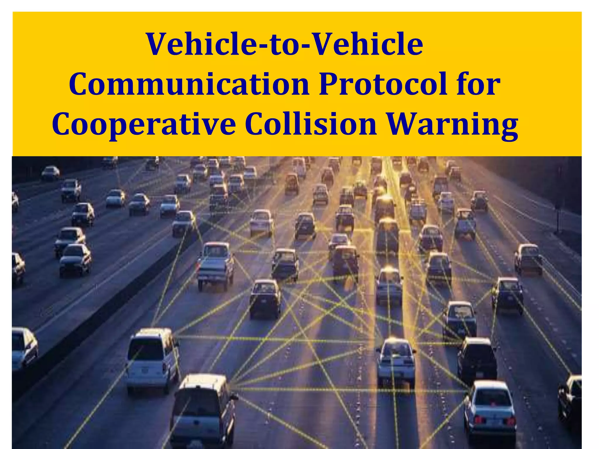
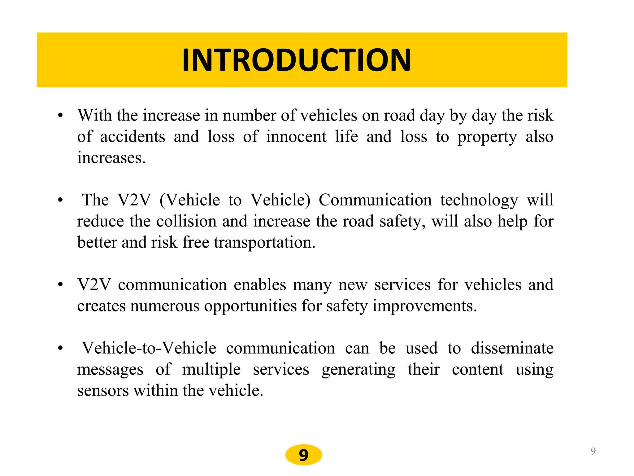
1
WELCOME
2
➢Traffic accidents have been taking thousands of lives
each year, outnumbering any deadly diseases or natural
disasters.
➢Between 1970 and 2011, the number of accidents
increased 4.4 times accompanied with 9.8 times increase
fatalities and 7.3 times increase in the number of
persons injured.
Accidents have been taking thousands of lives each year
3
1. Line of Sight Limitation
What’s in front of
that bus ?
What’s behind
the bend ?
On rainy days
On foggy days
Constraints of human drivers’ perception
Fig.1
4
2. Large forwarding delay for emergency events.
Constraints of human drivers’ perception
Three Cars, namely
Car A
Car B
Car C
Reaction time ranges from 0.7sec to 1.5sec
Animation. 1
5
6
DR AMBEDKAR INSTITUTE OF TECHNOLOGY
DEPARTMENT OF ELECTRONICS AND INSTRUMENTATION
ENGINEERING
A TECHNICAL SEMINAR ON
A VEHICLE-TO-VEHICLE COMMUNICATION PROTOCOL FOR
COOPERATIVE COLLISION WARNING
SUBMITTED BY
VIJAYALAKSHMI R JOGER
1DA14EI052
UNDER THE GUIDANCE OF
SHUBHA P
ASSISTANT PROFESSOR
EIE DEPT ,Dr AIT
7
Vehicle-to-Vehicle
Communication Protocol for
Cooperative Collision Warning
8
Contents
• Introduction
• Literature survey
• Overview of Vehicular Communications
• Needs and Assumptions
• Protocol for Vehicular Comm.
• Application Challenges
• State Transition
• Application Levels
• Future Works
• Conclusion
References
9 9
INTRODUCTION
• With the increase in number of vehicles on road day by day the risk
of accidents and loss of innocent life and loss to property also
increases.
• The V2V (Vehicle to Vehicle) Communication technology will
reduce the collision and increase the road safety, will also help for
better and risk free transportation.
• V2V communication enables many new services for vehicles and
creates numerous opportunities for safety improvements.
• Vehicle-to-Vehicle communication can be used to disseminate
messages of multiple services generating their content using
sensors within the vehicle.
1
0
1. Vehicle-to-vehicle and road-side sensor communication for enhanced road
safety, Andreas Festag, Alban Hessler, Roberto Baldessari, Long Le, Wenhui
Zhang, Dirk West off NEC Laboratories Europe, Network Research Division
Kurf¨ursten-Anlage 36, D-69115 Heidelberg 2012.
• This paper propose a hybrid ITS safety architecture that combines vehicle-
to-vehicle communication and vehicle-to-roadside sensor communication.
• The paper introduces accident prevention and post-accident investigation.
2. Vehicle-to-Vehicle Wireless Communication Protocols for Enhancing
Highway Traffic Safety, Subir Biswas, Michigan State University Raymond
Tatchikou, University of Kaiserslautern Francois Dion, Michigan State
University 2013.
• This article presents an overview of highway cooperative collision avoidance
(CCA), which is an emerging vehicular safety application
• Mobile Ad Hoc networks are used.
10
LITERATURE SURVEY
1
1
3. A Vehicle-to-Vehicle Communication Protocol for Cooperative Collision
Warning, Xue Yang University of Illinois at Urbana-Champaign 2012.
• To achieve low-latency in delivering emergency warnings in various road
situations.
11
1
2
Communication
Hot Spots (DSRC)
Satellite
to Vehicle
(GPS)
Vehicle
-
to-
Roadside
(DSRC)
Overview of Different Vehicular Communications
Petrol Pump,
Workshop etc..
( V2V )
( V2R )
Vehicle
to
vehicle
1
3
How wireless communication helps in
V2V communication?
Car A
Car B
Car C
1
4
Protocol for Vehicular Comm.
• Technology for ITS especially for v2v and v2r communication
• Service rules for DSRC are developed by the ASTM
(American Society for Testing and Materials )
• DSRC is based on IEEE 802.11a technology
10mMin. Separation
1000mMax Range
1-54MbpsData Rate
7 channelsChannels
QPSK OFDMModulation
75MHz (5.850 – 5.925GHz)Bandwidth
DSRC (Dedicated Short Range Communication)
1
5
Terms
• Abnormal Vehicle (AV)
A vehicle acts abnormally, e.g. deceleration exceeding a
certain threshold, dramatic change of moving direction,
major mechanical failure, etc.
• Emergency Warning Messages (EWM)
Messages generated by an AV to warn other
surrounding vehicles, which include the geographical
location, speed, acceleration and moving direction of
the AV.
1
6
➢ Using V2V communication, an AV actively generates
Emergency Warning Messages (EWMs), which include
the geographical location, speed, acceleration and
moving direction of the AV, to warn other surrounding
vehicles.
Application challenges
1
7
Application Challenges <1>
➢Stringent delay requirements immediately after
the emergency
1
8
➢ Over a short period immediately after an emergency
event, the faster the warning is delivered to the
endangered vehicles, the more likely accidents can be
avoided.
➢ We define EWM delivery delay from an AV A to a vehicle
V as the elapsed duration from the time the emergency
occurs at A to the time the first corresponding EWM
message is successfully received by V.
➢ Since a vehicle moving at the speed of 80 miles/hour can
cross more than one meter in 30ms , the EWM delivery
delay for each affected vehicle should be in the order of
milliseconds.
➢ In an abnormal situation, all vehicles close to the AV may
be potentially endangered and they all should receive the
timely emergency warning.
1
9
Application Challenges <2>
➢ Support of multiple co-existing AVs over a
longer period
2
0
➢ After an emergency event happens, the AV can stay in
the abnormal state for a period of time.
➢ For example, if a vehicle stops in the middle of a
highway due to mechanical failure, it remains
hazardous to any approaching vehicles,and hence,
remains an abnormal vehicle until it is removed off the
road.
➢ emergency road situations frequently have chain
effects.When a leading vehicle applies an emergency
brake,it is probable that vehicles behind it will react by
also decelerating suddenly.
2
1
Application Challenges <3>
➢Differentiation of emergency events and
elimination of redundant EWMs
2
2
➢ Emergency events from AVs following different
lanes/trajectories usually have different impact on
surrounding vehicles, hence, should be differentiated
from each other.
➢ multiple AVs may react to a same emergency event and
impose similar danger to the approaching vehicles.
2
3
VEHICULAR COLLISION WARNING
COMMUNICATION PROTOCOL
➢ Each message used in VCWC protocol is intended for a
group of receivers, and the group of intended receivers
changes fast due to high mobility of vehicles, which
necessitate the message transmissions using broadcast
instead of unicast.
➢ To ensure reliable delivery of emergency warnings over
unreliable wireless channel, EWMs need to be repeatedly
transmitted.
2
4
for a vehicle participating in V2V communication
• Is able to obtain its own geographical location and
determine the relative positions on the road.(Digital
Maps, GPS)
Needs and Assumptions
2
5
• Is equipped with at least one wireless
transceiver
2
6
➢ In VCWC, different kinds of messages are assigned different
priority levels,
Highest priority- EWM’s
➢ considering the EWM congestion control, we can focus on the
transmissions of EWMs alone.
➢ The goal of the rate decreasing algorithm is to achieve low EWM
delivery delay at the time of an emergency event, while allowing
a large number of co-existing AVs.
➢ Retransmission delay due to
● poor channel conditions
● packet collisions
Rate Decreasing Algorithm for EWMs
2
7
● EWM delivery delay from A to Z can be formally defined as the
elapsed duration from the time the emergency occurs at A to the
time the first corresponding EWM message is successfully
received by Z.
➢ Waiting time of an EWM message: the duration from the
time the EWM is issued by the vehicular collision warning
communication module to the time it is transmitted on the
wireless channel
u-Channel service rate
λ-total arrival time
2
8
Waiting time and retransmission delay
2
9
EWM retransmission delay:the elapsed duration from the
time when the first EWM is generated to the time when the
ith EWM is generated by the AV A.
p - the probability for an EWM message being correctly
received by a vehicle
λ0 - initial EWM transmission rate
f(λ0,k) -the EWM transmission rate after kth the
transmitted EWM for an AV.
3
0
➢ EWM delivery delay can be represented
as
➢ EWM transmission rate of an AV is decreased by a
factor a of after every L transmitted EWMs, until the
minimum rate is reached.
λmin-min total arrival time
λ0-initial EWM transmission
rate
3
1
3
2
3
3
● constant rate algorithm→ when a=1
● multiplicative rate decreasing algorithm→ when
a=2
➢the network becomes unstable when approaches
25 using the constant rate algorithm
➢nearly 100 co-existing AVs can be supported before
the EWM delivery delay begins to soar using the
multiplicative rate decreasing algorithm with a=2 .
➢multiplicative rate decreasing algorithm leads to
very little degradation of retransmission delay.
3
4
➢ The objective of the state transition mechanism is to ensure
EWM coverage for the endangered regions and to eliminate
redundant EWMs, while incurring little control overhead.
➢Each AV may be in one of three states:
➢ Initial AV: When an emergency event occurs to a vehicle, the
vehicle becomes an AV and enters the initial AV state,
transmitting EWMs following the rate decreasing algorithm.
➢ Non-flagger AV: nonparticipating in sending EWMs to the
group on some conditions to eliminate redundant EWMs.
➢ Flagger AV: resuming EWM transmissions at the minimum
required rate.
STATE TRANSITIONS OF AV’S AND
ELIMINATION OF REDUNDANT EWM’S
3
5
Examples of state transitions
3
6
Examples of state transitions (cont.)
Fig. 5d
3
7
3
8
➢ At time 0s the leading vehicle becomes an AV, and starts
to send EWMs. As the driver reaction time ranges from
0.7 seconds to 1.5 seconds, the number of EWMs surges
from 1s to 2s when all the trailing vehicles located within
the transmission range of the leading vehicle become
AVs.
➢ Redundant EWMs are effectively eliminated as the
amount of EWMs drops significantly from time 2s to 3s. In
the end, with perfect channel condition, only one AV
remains transmitting EWMs at the rate of 10
messages/sec.
➢ When channel condition is bad, say p=0.5 slightly more
EWMs may be transmitted from time to time.
3
9
4
0
➢ The amount of channel bandwidth consumed by EWM
messages can be revealed from the throughput loss of nontime-
sensitive traffic.
➢ The throughput obtained by the non time- sensitive traffic, which
is also measured over each second.
➢ The curves marked as “base throughput” show the throughput
obtained by non-time sensitive traffic when there is no emergency
event.
➢ Starting from time 3s, non-time-sensitive traffic suffers very little
throughput loss. When channel condition is bad, say p=0.5 , the
relative throughput loss is even smaller comparing with p=1
because the base throughput itself is very low with poor channel
condition.
4
1
Application
● Traffic Safety can be improved if drivers have the ability to
see further down the road.
● Vehicle-to-Vehicle(V2V) and Vehicle-to-Roadside(V2R)
Communication can bring out the following achievements.
• Presence of obstacles on road.
• Emergency Braking of a preceding vehicle.
• Information about Blind Crossing, School proximity, Railway crossing
etc
• Entries to Highways.
• Electronic Toll Collection.
• Parking Space locater in Cities.
• Nearest Petrol Pump, Workshop etc..
HIGHWAY/RAIL INTERSECTION WARNING
Highway Crossing
Railroad Warning
Signal,Train
Detection Receiver
Traffic Signal
Train Transmitter on Railroad
Frequency
COMMUNICATION ZONES
RSU in Railroad Warning Sign
on Control Ch
HIGHWAY/RAIL INTERSECTION WARNING
Highway Crossing
Railroad
Warning Signal
Traffic Signal
Train Transmitter on
Railroad Frequency
EXAMPLE
COMMUNICATION ZONES
OBU on Control Channel
RSU in Railroad Warning
Sign on Control
⦁ By this technology, people’s drive will be
more comfortable and easier.
⦁ The case of accidents will be very less.
⦁ Any problem occurred by one in driving will
be informed to others so they can be aware of
it while driving.
⦁ Improving traffic management.
⦁ Providing driver assistance.
⦁ Providing Direction and Route Optimization.
ADVANTAGES
4
5
⦁ Any small occur in the working of
vehicle will leads to the total disturbance of
the one’s drive.
DISADVANTAGES
4
6
Future Works
• Vehicle manufacturers would install the technology in all new vehicles,
beginning at a particular model year
• Full-scale deployment in both the vehicles and the roadside
infrastructure will be made by 2008/9
USDOT Intelligent Transportation Systems (ITS) Program
4
7
Hi
Buddy
A new era is arriving where vehicles will communicate
with each other, the devices within them, and also with the
world; making the next generation of vehicles into
communication hubs.
Conclusion
4
8
References
[1] S. Biswas, "Vehicle-to-Vehicle Wireless Communication Protocols for Enhancing
Highway Traffic Safety," Communications Magazine, IEEE Publication Date:
Jan. 2006 Volume: 44, Issue: 1 page(s):74- 82
[2] X. Yang et al., " A Vehicle-to-Vehicle Communication Protocol for Cooperative
Collision Warning,"Proc. 1st Annual Int’l. Conf. Mobile and Ubiquitous Syst:
Networking and Services, 2004
[3] G.S Bickel, "Inter/Intra-Vehicle Wireless Communication" at
http://userfs.cec.wustl.edu/~gsb1/index.html
[4] Q. Xu, R. Sengupta, and D. Jiang, "Design and Analysis of Highway Safety
Communication Protocol in 5.9 GHz Dedicated Short-Range Communication
Spectrum," Proc. IEEE VTC, vol. 57, no. 4, 2003, pp. 2451–55
[5] C.Bettstetter "Toward Internet-Based Car Communications: On Some System
Architecture And Protocol Aspects" TUM, Germany
[6] J. Zhu and S. Roy, "MAC for Dedicated Short Range Communications in
Intelligent Transport Systems,"IEEE Commun. Mag., vol. 41, no. 12, 2003
[7] http://www.car-to-car.org/
4
9
THANK YOU
5
0
Questions ?

Vehicle to vehicle communication

  • 1.
  • 2.
    2 ➢Traffic accidents havebeen taking thousands of lives each year, outnumbering any deadly diseases or natural disasters. ➢Between 1970 and 2011, the number of accidents increased 4.4 times accompanied with 9.8 times increase fatalities and 7.3 times increase in the number of persons injured. Accidents have been taking thousands of lives each year
  • 3.
    3 1. Line ofSight Limitation What’s in front of that bus ? What’s behind the bend ? On rainy days On foggy days Constraints of human drivers’ perception Fig.1
  • 4.
    4 2. Large forwardingdelay for emergency events. Constraints of human drivers’ perception Three Cars, namely Car A Car B Car C Reaction time ranges from 0.7sec to 1.5sec Animation. 1
  • 5.
  • 6.
    6 DR AMBEDKAR INSTITUTEOF TECHNOLOGY DEPARTMENT OF ELECTRONICS AND INSTRUMENTATION ENGINEERING A TECHNICAL SEMINAR ON A VEHICLE-TO-VEHICLE COMMUNICATION PROTOCOL FOR COOPERATIVE COLLISION WARNING SUBMITTED BY VIJAYALAKSHMI R JOGER 1DA14EI052 UNDER THE GUIDANCE OF SHUBHA P ASSISTANT PROFESSOR EIE DEPT ,Dr AIT
  • 7.
  • 8.
    8 Contents • Introduction • Literaturesurvey • Overview of Vehicular Communications • Needs and Assumptions • Protocol for Vehicular Comm. • Application Challenges • State Transition • Application Levels • Future Works • Conclusion References
  • 9.
    9 9 INTRODUCTION • Withthe increase in number of vehicles on road day by day the risk of accidents and loss of innocent life and loss to property also increases. • The V2V (Vehicle to Vehicle) Communication technology will reduce the collision and increase the road safety, will also help for better and risk free transportation. • V2V communication enables many new services for vehicles and creates numerous opportunities for safety improvements. • Vehicle-to-Vehicle communication can be used to disseminate messages of multiple services generating their content using sensors within the vehicle.
  • 10.
    1 0 1. Vehicle-to-vehicle androad-side sensor communication for enhanced road safety, Andreas Festag, Alban Hessler, Roberto Baldessari, Long Le, Wenhui Zhang, Dirk West off NEC Laboratories Europe, Network Research Division Kurf¨ursten-Anlage 36, D-69115 Heidelberg 2012. • This paper propose a hybrid ITS safety architecture that combines vehicle- to-vehicle communication and vehicle-to-roadside sensor communication. • The paper introduces accident prevention and post-accident investigation. 2. Vehicle-to-Vehicle Wireless Communication Protocols for Enhancing Highway Traffic Safety, Subir Biswas, Michigan State University Raymond Tatchikou, University of Kaiserslautern Francois Dion, Michigan State University 2013. • This article presents an overview of highway cooperative collision avoidance (CCA), which is an emerging vehicular safety application • Mobile Ad Hoc networks are used. 10 LITERATURE SURVEY
  • 11.
    1 1 3. A Vehicle-to-VehicleCommunication Protocol for Cooperative Collision Warning, Xue Yang University of Illinois at Urbana-Champaign 2012. • To achieve low-latency in delivering emergency warnings in various road situations. 11
  • 12.
    1 2 Communication Hot Spots (DSRC) Satellite toVehicle (GPS) Vehicle - to- Roadside (DSRC) Overview of Different Vehicular Communications Petrol Pump, Workshop etc.. ( V2V ) ( V2R ) Vehicle to vehicle
  • 13.
    1 3 How wireless communicationhelps in V2V communication? Car A Car B Car C
  • 14.
    1 4 Protocol for VehicularComm. • Technology for ITS especially for v2v and v2r communication • Service rules for DSRC are developed by the ASTM (American Society for Testing and Materials ) • DSRC is based on IEEE 802.11a technology 10mMin. Separation 1000mMax Range 1-54MbpsData Rate 7 channelsChannels QPSK OFDMModulation 75MHz (5.850 – 5.925GHz)Bandwidth DSRC (Dedicated Short Range Communication)
  • 15.
    1 5 Terms • Abnormal Vehicle(AV) A vehicle acts abnormally, e.g. deceleration exceeding a certain threshold, dramatic change of moving direction, major mechanical failure, etc. • Emergency Warning Messages (EWM) Messages generated by an AV to warn other surrounding vehicles, which include the geographical location, speed, acceleration and moving direction of the AV.
  • 16.
    1 6 ➢ Using V2Vcommunication, an AV actively generates Emergency Warning Messages (EWMs), which include the geographical location, speed, acceleration and moving direction of the AV, to warn other surrounding vehicles. Application challenges
  • 17.
    1 7 Application Challenges <1> ➢Stringentdelay requirements immediately after the emergency
  • 18.
    1 8 ➢ Over ashort period immediately after an emergency event, the faster the warning is delivered to the endangered vehicles, the more likely accidents can be avoided. ➢ We define EWM delivery delay from an AV A to a vehicle V as the elapsed duration from the time the emergency occurs at A to the time the first corresponding EWM message is successfully received by V. ➢ Since a vehicle moving at the speed of 80 miles/hour can cross more than one meter in 30ms , the EWM delivery delay for each affected vehicle should be in the order of milliseconds. ➢ In an abnormal situation, all vehicles close to the AV may be potentially endangered and they all should receive the timely emergency warning.
  • 19.
    1 9 Application Challenges <2> ➢Support of multiple co-existing AVs over a longer period
  • 20.
    2 0 ➢ After anemergency event happens, the AV can stay in the abnormal state for a period of time. ➢ For example, if a vehicle stops in the middle of a highway due to mechanical failure, it remains hazardous to any approaching vehicles,and hence, remains an abnormal vehicle until it is removed off the road. ➢ emergency road situations frequently have chain effects.When a leading vehicle applies an emergency brake,it is probable that vehicles behind it will react by also decelerating suddenly.
  • 21.
    2 1 Application Challenges <3> ➢Differentiationof emergency events and elimination of redundant EWMs
  • 22.
    2 2 ➢ Emergency eventsfrom AVs following different lanes/trajectories usually have different impact on surrounding vehicles, hence, should be differentiated from each other. ➢ multiple AVs may react to a same emergency event and impose similar danger to the approaching vehicles.
  • 23.
    2 3 VEHICULAR COLLISION WARNING COMMUNICATIONPROTOCOL ➢ Each message used in VCWC protocol is intended for a group of receivers, and the group of intended receivers changes fast due to high mobility of vehicles, which necessitate the message transmissions using broadcast instead of unicast. ➢ To ensure reliable delivery of emergency warnings over unreliable wireless channel, EWMs need to be repeatedly transmitted.
  • 24.
    2 4 for a vehicleparticipating in V2V communication • Is able to obtain its own geographical location and determine the relative positions on the road.(Digital Maps, GPS) Needs and Assumptions
  • 25.
    2 5 • Is equippedwith at least one wireless transceiver
  • 26.
    2 6 ➢ In VCWC,different kinds of messages are assigned different priority levels, Highest priority- EWM’s ➢ considering the EWM congestion control, we can focus on the transmissions of EWMs alone. ➢ The goal of the rate decreasing algorithm is to achieve low EWM delivery delay at the time of an emergency event, while allowing a large number of co-existing AVs. ➢ Retransmission delay due to ● poor channel conditions ● packet collisions Rate Decreasing Algorithm for EWMs
  • 27.
    2 7 ● EWM deliverydelay from A to Z can be formally defined as the elapsed duration from the time the emergency occurs at A to the time the first corresponding EWM message is successfully received by Z. ➢ Waiting time of an EWM message: the duration from the time the EWM is issued by the vehicular collision warning communication module to the time it is transmitted on the wireless channel u-Channel service rate λ-total arrival time
  • 28.
    2 8 Waiting time andretransmission delay
  • 29.
    2 9 EWM retransmission delay:theelapsed duration from the time when the first EWM is generated to the time when the ith EWM is generated by the AV A. p - the probability for an EWM message being correctly received by a vehicle λ0 - initial EWM transmission rate f(λ0,k) -the EWM transmission rate after kth the transmitted EWM for an AV.
  • 30.
    3 0 ➢ EWM deliverydelay can be represented as ➢ EWM transmission rate of an AV is decreased by a factor a of after every L transmitted EWMs, until the minimum rate is reached. λmin-min total arrival time λ0-initial EWM transmission rate
  • 31.
  • 32.
  • 33.
    3 3 ● constant ratealgorithm→ when a=1 ● multiplicative rate decreasing algorithm→ when a=2 ➢the network becomes unstable when approaches 25 using the constant rate algorithm ➢nearly 100 co-existing AVs can be supported before the EWM delivery delay begins to soar using the multiplicative rate decreasing algorithm with a=2 . ➢multiplicative rate decreasing algorithm leads to very little degradation of retransmission delay.
  • 34.
    3 4 ➢ The objectiveof the state transition mechanism is to ensure EWM coverage for the endangered regions and to eliminate redundant EWMs, while incurring little control overhead. ➢Each AV may be in one of three states: ➢ Initial AV: When an emergency event occurs to a vehicle, the vehicle becomes an AV and enters the initial AV state, transmitting EWMs following the rate decreasing algorithm. ➢ Non-flagger AV: nonparticipating in sending EWMs to the group on some conditions to eliminate redundant EWMs. ➢ Flagger AV: resuming EWM transmissions at the minimum required rate. STATE TRANSITIONS OF AV’S AND ELIMINATION OF REDUNDANT EWM’S
  • 35.
  • 36.
    3 6 Examples of statetransitions (cont.) Fig. 5d
  • 37.
  • 38.
    3 8 ➢ At time0s the leading vehicle becomes an AV, and starts to send EWMs. As the driver reaction time ranges from 0.7 seconds to 1.5 seconds, the number of EWMs surges from 1s to 2s when all the trailing vehicles located within the transmission range of the leading vehicle become AVs. ➢ Redundant EWMs are effectively eliminated as the amount of EWMs drops significantly from time 2s to 3s. In the end, with perfect channel condition, only one AV remains transmitting EWMs at the rate of 10 messages/sec. ➢ When channel condition is bad, say p=0.5 slightly more EWMs may be transmitted from time to time.
  • 39.
  • 40.
    4 0 ➢ The amountof channel bandwidth consumed by EWM messages can be revealed from the throughput loss of nontime- sensitive traffic. ➢ The throughput obtained by the non time- sensitive traffic, which is also measured over each second. ➢ The curves marked as “base throughput” show the throughput obtained by non-time sensitive traffic when there is no emergency event. ➢ Starting from time 3s, non-time-sensitive traffic suffers very little throughput loss. When channel condition is bad, say p=0.5 , the relative throughput loss is even smaller comparing with p=1 because the base throughput itself is very low with poor channel condition.
  • 41.
    4 1 Application ● Traffic Safetycan be improved if drivers have the ability to see further down the road. ● Vehicle-to-Vehicle(V2V) and Vehicle-to-Roadside(V2R) Communication can bring out the following achievements. • Presence of obstacles on road. • Emergency Braking of a preceding vehicle. • Information about Blind Crossing, School proximity, Railway crossing etc • Entries to Highways. • Electronic Toll Collection. • Parking Space locater in Cities. • Nearest Petrol Pump, Workshop etc..
  • 42.
    HIGHWAY/RAIL INTERSECTION WARNING HighwayCrossing Railroad Warning Signal,Train Detection Receiver Traffic Signal Train Transmitter on Railroad Frequency COMMUNICATION ZONES RSU in Railroad Warning Sign on Control Ch
  • 43.
    HIGHWAY/RAIL INTERSECTION WARNING HighwayCrossing Railroad Warning Signal Traffic Signal Train Transmitter on Railroad Frequency EXAMPLE COMMUNICATION ZONES OBU on Control Channel RSU in Railroad Warning Sign on Control
  • 44.
    ⦁ By thistechnology, people’s drive will be more comfortable and easier. ⦁ The case of accidents will be very less. ⦁ Any problem occurred by one in driving will be informed to others so they can be aware of it while driving. ⦁ Improving traffic management. ⦁ Providing driver assistance. ⦁ Providing Direction and Route Optimization. ADVANTAGES
  • 45.
    4 5 ⦁ Any smalloccur in the working of vehicle will leads to the total disturbance of the one’s drive. DISADVANTAGES
  • 46.
    4 6 Future Works • Vehiclemanufacturers would install the technology in all new vehicles, beginning at a particular model year • Full-scale deployment in both the vehicles and the roadside infrastructure will be made by 2008/9 USDOT Intelligent Transportation Systems (ITS) Program
  • 47.
    4 7 Hi Buddy A new erais arriving where vehicles will communicate with each other, the devices within them, and also with the world; making the next generation of vehicles into communication hubs. Conclusion
  • 48.
    4 8 References [1] S. Biswas,"Vehicle-to-Vehicle Wireless Communication Protocols for Enhancing Highway Traffic Safety," Communications Magazine, IEEE Publication Date: Jan. 2006 Volume: 44, Issue: 1 page(s):74- 82 [2] X. Yang et al., " A Vehicle-to-Vehicle Communication Protocol for Cooperative Collision Warning,"Proc. 1st Annual Int’l. Conf. Mobile and Ubiquitous Syst: Networking and Services, 2004 [3] G.S Bickel, "Inter/Intra-Vehicle Wireless Communication" at http://userfs.cec.wustl.edu/~gsb1/index.html [4] Q. Xu, R. Sengupta, and D. Jiang, "Design and Analysis of Highway Safety Communication Protocol in 5.9 GHz Dedicated Short-Range Communication Spectrum," Proc. IEEE VTC, vol. 57, no. 4, 2003, pp. 2451–55 [5] C.Bettstetter "Toward Internet-Based Car Communications: On Some System Architecture And Protocol Aspects" TUM, Germany [6] J. Zhu and S. Roy, "MAC for Dedicated Short Range Communications in Intelligent Transport Systems,"IEEE Commun. Mag., vol. 41, no. 12, 2003 [7] http://www.car-to-car.org/
  • 49.
  • 50.