Downloaded 31 times
![IJRET: International Journal of Research in Engineering and Technology eISSN: 2319-1163 | pISSN: 2321-7308
_______________________________________________________________________________________
Volume: 04 Issue: 06 | June-2015, Available @ http://www.ijret.org 367
SEISMIC POUNDING BETWEEN ADJACENT RC BUILDINGS WITH
AND WITHOUT BASE ISOLATION SYSTEM
Raghunandan M H1
, Suma Devi2
1
Post Graduate student, Structural Engineering, SVCE Bangalore, Karnataka, India
2
Assistant Professor, Civil Engineering, SVCE Bangalore, Karnataka, India
Abstract
Among the possible structural damages during an earthquake, the seismic induced pounding also has been one of the commonly
observed phenomena. This is because the separation gap between many adjacent buildings is inadequate to accommodate the
relative motions, so buildings vibrate out of phase and collides. Despite the fact that the seismic pounding between nearby
structures is considered in the codal procurements, the act of development is still an issue in numerous metropolitan zones where
the structures are built with no adequate partition separation which brings about their pounding. In this study E-Tabs nonlinear
software is used for simulation of adjacent multi-storeyed RC frame buildings of G+14 and G+9 storey, the provisions that may
reduce the effects of pounding like the separation distance, addition of shear walls, lateral bracings and variation in storey height
of the buildings have been considered for analysis. And the responses like storey-displacement and pounding force by considering
both fixed base and base-isolated conditions are arrived.
Keywords: Seismic pounding, RC frame building, Separation distance, Gap elements, Storey-displacement Pounding
force, Fixed-base, Base isolation.
--------------------------------------------------------------------***-----------------------------------------------------------------
1. INTRODUCTION
This seismic pounding causes severe damage to the
structures under earthquakes, owing to their different
dynamic characteristics. During earthquake the building
structures vibrate in out of phase and the separation is not
sufficient to accommodate their relative motions. But this
collision can be avoided by providing safe separation
distance also called as seismic gap; however sometimes
getting the required safe separations is not possible in
metropolitan areas, due to increase in land values and
population [1]. So the buildings may have been constructed
very close to each other and the existing space between
those buildings may not be enough for avoiding the
pounding. Although the seismic pounding between fixed-
base buildings had been studied exclusively for more than
decades, the seismic pounding between base-isolated
buildings had not drawn much attention. Also the past
earthquakes showed us the detrimental effects caused by
seismic pounding on performance of the conventional
buildings with fixed base, which ranges from the local
damage to severe structural failure. But, the consequences of
earthquake induced pounding on the seismically isolated
buildings may be more substantial and those required being
assessed [6]. Thus there is a need for studying the effects of
isolated buildings on pounding as well as of pounding on
base isolated buildings. If the building separation is found to
be inefficient for avoiding the pounding, then there should
be some suitable methods for preventing the structural
pounding between adjacent buildings. This can be achieved
by including superior design procedures for making the
buildings stable against strong ground motions. Since
distance between the buildings cannot be increased in case
of existing buildings and new buildings due to
constructional difficulties, so we have to arrive at an
alternate solution for this problem. This is done by
enhancing the lateral stiffness of one building or both the
buildings by providing the shear walls or lateral bracings in
a way that it will reduce the displacement and can be
accommodated between the available separation distances.
On the other hand if the strength and stiffness of a frame is
not adequate then the frame system may be strengthened by
including load-bearing walls, lateral bracings or shear walls.
Bracings and shear walls are also helpful in preventing the
failure of non-structural components by reducing the
deflection. Shear walls or lateral bracings located at suitable
positions in a building can significantly resist lateral loads
due to earthquake or wind. These may be of RCC, steel or
composite etc. Both lateral bracings and shear walls are used
as effective mitigation strategies. The location of shear walls
in building are selected in such a way, that the distance
between center of mass and center of rigidity is kept as low
as possible in order to reduce the additional forces
developed due to torsion.
1.1 Base Isolation System
The base isolation technology is one of the most innovative
approaches for anti-seismic designing of the structures that
has been widely used from last few years. The term base
isolation in which the word isolation means state of being
separated and the word base is a part that supports beneath
or serves as a foundation for super structure. So we can
understand this concept as the structures which are separated
from their foundation. In other sense, the term seismic
isolation is more accurate in which the structure is being](https://image.slidesharecdn.com/seismicpoundingbetweenadjacentrcbuildingswithandwithoutbaseisolationsystem-160906105716/85/Seismic-pounding-between-adjacent-rc-buildings-with-and-without-base-isolation-system-1-320.jpg)
![IJRET: International Journal of Research in Engineering and Technology eISSN: 2319-1163 | pISSN: 2321-7308
_______________________________________________________________________________________
Volume: 04 Issue: 06 | June-2015, Available @ http://www.ijret.org 367
SEISMIC POUNDING BETWEEN ADJACENT RC BUILDINGS WITH
AND WITHOUT BASE ISOLATION SYSTEM
Raghunandan M H1
, Suma Devi2
1
Post Graduate student, Structural Engineering, SVCE Bangalore, Karnataka, India
2
Assistant Professor, Civil Engineering, SVCE Bangalore, Karnataka, India
Abstract
Among the possible structural damages during an earthquake, the seismic induced pounding also has been one of the commonly
observed phenomena. This is because the separation gap between many adjacent buildings is inadequate to accommodate the
relative motions, so buildings vibrate out of phase and collides. Despite the fact that the seismic pounding between nearby
structures is considered in the codal procurements, the act of development is still an issue in numerous metropolitan zones where
the structures are built with no adequate partition separation which brings about their pounding. In this study E-Tabs nonlinear
software is used for simulation of adjacent multi-storeyed RC frame buildings of G+14 and G+9 storey, the provisions that may
reduce the effects of pounding like the separation distance, addition of shear walls, lateral bracings and variation in storey height
of the buildings have been considered for analysis. And the responses like storey-displacement and pounding force by considering
both fixed base and base-isolated conditions are arrived.
Keywords: Seismic pounding, RC frame building, Separation distance, Gap elements, Storey-displacement Pounding
force, Fixed-base, Base isolation.
--------------------------------------------------------------------***-----------------------------------------------------------------
1. INTRODUCTION
This seismic pounding causes severe damage to the
structures under earthquakes, owing to their different
dynamic characteristics. During earthquake the building
structures vibrate in out of phase and the separation is not
sufficient to accommodate their relative motions. But this
collision can be avoided by providing safe separation
distance also called as seismic gap; however sometimes
getting the required safe separations is not possible in
metropolitan areas, due to increase in land values and
population [1]. So the buildings may have been constructed
very close to each other and the existing space between
those buildings may not be enough for avoiding the
pounding. Although the seismic pounding between fixed-
base buildings had been studied exclusively for more than
decades, the seismic pounding between base-isolated
buildings had not drawn much attention. Also the past
earthquakes showed us the detrimental effects caused by
seismic pounding on performance of the conventional
buildings with fixed base, which ranges from the local
damage to severe structural failure. But, the consequences of
earthquake induced pounding on the seismically isolated
buildings may be more substantial and those required being
assessed [6]. Thus there is a need for studying the effects of
isolated buildings on pounding as well as of pounding on
base isolated buildings. If the building separation is found to
be inefficient for avoiding the pounding, then there should
be some suitable methods for preventing the structural
pounding between adjacent buildings. This can be achieved
by including superior design procedures for making the
buildings stable against strong ground motions. Since
distance between the buildings cannot be increased in case
of existing buildings and new buildings due to
constructional difficulties, so we have to arrive at an
alternate solution for this problem. This is done by
enhancing the lateral stiffness of one building or both the
buildings by providing the shear walls or lateral bracings in
a way that it will reduce the displacement and can be
accommodated between the available separation distances.
On the other hand if the strength and stiffness of a frame is
not adequate then the frame system may be strengthened by
including load-bearing walls, lateral bracings or shear walls.
Bracings and shear walls are also helpful in preventing the
failure of non-structural components by reducing the
deflection. Shear walls or lateral bracings located at suitable
positions in a building can significantly resist lateral loads
due to earthquake or wind. These may be of RCC, steel or
composite etc. Both lateral bracings and shear walls are used
as effective mitigation strategies. The location of shear walls
in building are selected in such a way, that the distance
between center of mass and center of rigidity is kept as low
as possible in order to reduce the additional forces
developed due to torsion.
1.1 Base Isolation System
The base isolation technology is one of the most innovative
approaches for anti-seismic designing of the structures that
has been widely used from last few years. The term base
isolation in which the word isolation means state of being
separated and the word base is a part that supports beneath
or serves as a foundation for super structure. So we can
understand this concept as the structures which are separated
from their foundation. In other sense, the term seismic
isolation is more accurate in which the structure is being](https://image.slidesharecdn.com/seismicpoundingbetweenadjacentrcbuildingswithandwithoutbaseisolationsystem-160906105716/75/Seismic-pounding-between-adjacent-rc-buildings-with-and-without-base-isolation-system-1-2048.jpg)
![IJRET: International Journal of Research in Engineering and Technology eISSN: 2319-1163 | pISSN: 2321-7308
_______________________________________________________________________________________
Volume: 04 Issue: 06 | June-2015, Available @ http://www.ijret.org 368
separated from the ill effects of seismic motion [5]. The new
design philosophy on anti-seismic design criteria emerged
aiming for reducing the seismic damages by providing
isolators at the base of the structures. However, in
seismically isolated structures the peak base displacement
increases significantly during earthquake and the structure
can impact on adjacent structures like buildings, retaining
walls, ramps, boundary walls etc. In case of longer buildings
the expansion gaps are provided invariably in order to
accommodate the displacements due to variation in
temperature. For such buildings there are likely chances of
impact at their expansion gap when these two buildings
vibrate out of phase.
1.2 Lead Rubber Bearing (LRB)
This is a type of elastomeric bearing having higher value of
damping which is obtained by arranging a core of lead in the
centre of the bearing, where the energy absorption is
obtained by yielding of the lead, which remains hooped by
the thin layers of low damping natural rubber and alternate
layers of steel plates.
1.3 Gap Elements
Gap element is an element which connects two adjacent
nodes to model the contact and is defined as a link element
in ETABS software, this link element is activated only when
the structures come closer and deactivate when they go far
away and a collision force will be generated when they
come closer. So it is a compression-only element required to
assess the pounding force and to simulate the effect of
pounding.
1.4 Analysis Methods
Equivalent Static Analysis: Seismic analysis of most
structures is still carried out on the assumption that the
lateral force is equivalent to the actual loading. This method
of finding design lateral forces is also known as the static
method or the equivalent lateral force method or the seismic
coefficient method.
Response Spectrum Analysis: This method is also known
as modal method or mode superposition method. In the
response spectrum method, the peak response of a structure
during an earthquake is obtained directly from the
earthquake response spectrum. The responses of different
modes are combined to provide an estimate of total response
of the structure using modal combination methods such as
complete quadratic combinations (CQC), square root of sum
of squares (SRSS), or absolute sum (ABS) method.
Time History Analysis: A time history analysis overcomes
all the disadvantages of a modal response spectrum analysis.
This method requires greater computational efforts for
calculating the response at discrete times. One interesting
advantage of such a procedure is that the relative signs of
response quantities are preserved in the response histories.
This is important when interaction effects are considered
among stress resultants [7].
2. METHODOLOGY
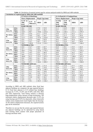
The multi-storeyed RC frame buildings are modelled in
ETABS nonlinear software. The two buildings consist of
G+14 and G+9 special moment resisting frame considered
to be situated in seismic zone V having medium soil and
intended for residential use and separated by an initial gap of
50mm. Both buildings are modelled in E-tabs software, are
subjected to gravity and dynamic loads are analysed by
equivalent static analysis and response spectrum analysis
methods. And to observe pounding, time history analysis is
carried out taking data of Elcentro.
Pounding is considered at slab level of tenth storey, for
observing positive displacement of G+14 storey building
and negative displacement of G+9 storey building. Beams
and column members have been defined as frame elements
and the columns have been restrained in all six degrees of
freedom at the base. Slabs are defined as area elements
having the properties of membrane elements and have been
modelled as rigid diaphragms. Also concrete bracings and
shear walls are defined as frame elements and shell area
elements respectively.
Building 1 and 2 having grade of concrete for beam, slab,
brace and shear wall is M20 and for column is M25, with
unit weight of concrete being 25kN/m3
, Column size for
building 1 and 2 is taken as 0.6 x 1 m, while the beam size is
0.35 x 0.6 m and bracing size of 0.2 x 0.2 m. The slab
thickness of 130 mm and shear wall thickness of 200mm are
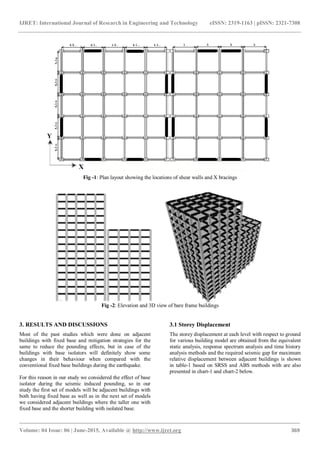
taken. Building 1 having G+14 storeys with 5 bays in X and
Y directions, width of bay in X direction is 4.5 m and in Y
direction is 4.5 m. Building 2 having G+9 storeys with 4
bays in X, 5 bays in Y direction, and width of bay in X
direction is 4 m and in Y direction is 5 m.](https://image.slidesharecdn.com/seismicpoundingbetweenadjacentrcbuildingswithandwithoutbaseisolationsystem-160906105716/85/Seismic-pounding-between-adjacent-rc-buildings-with-and-without-base-isolation-system-2-320.jpg)
![IJRET: International Journal of Research in Engineering and Technology eISSN: 2319-1163 | pISSN: 2321-7308
_______________________________________________________________________________________
Volume: 04 Issue: 06 | June-2015, Available @ http://www.ijret.org 374
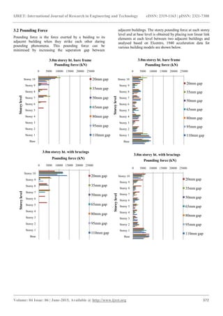
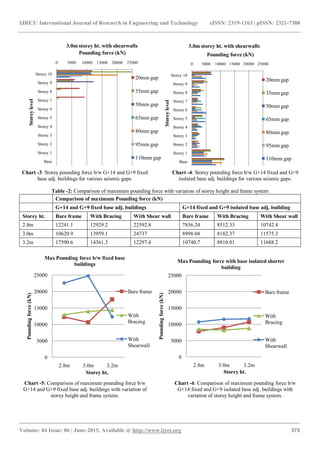
From the above chart 3 and 4 we can observe that incase of
G+14 and G+9 fixed base adjacent buildings pounding
effect is experienced only at few of the top storeys and the
force non linearly varies and diminishes with increase in
seperation distance. But in case of G+14 fixed adjacent to
G+9 isolated-base building the effect can be seen through
the height of the buildings. Also we see the maximum
pounding force at the top for G+14 and G+9 fixed base
adjacent buildings, where as for G+14 fixed adjacent to G+9
isolated base building the maximum pounding force is at the
base level.
From table-2, chart 5 and 6 we found that both incase of the
G+14 and G+9 fixed base adjacent buildings and G+14
fixed adjacent to G+9 isolated base building the presence of
shearwalls shows maximum pounding force when compared
with bare framed or withbracings. And the bracings in
buildings helps in maintaining the linearity of pounding
force with variation of storey height. Therefore we can say
that the pounding effect between any adjacent buildings can
be optimized by use of bracings and increase in seperation
gap between them.
4. CONCLUSION
4.1 Storey Displacement
Storey displacement value increases with increase in
the storey height or building height. Use of isolators
induces displacement even at the base level in addition
to increase in top displacement when compared to
fixed base building.
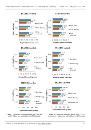
The gap required between fixed base taller adjacent to
isolated base shorter buildings increases by 5-15%, 15-
25% and 25-40% with ESA, RSA and THA
respectively when compared with fixed base adjacent
buildings.
The maximum relative displacement decreases by
using bracings and shearwalls. As relative
displacement decreases, the required seismic gap can
be minimized.
4.2 Pounding Force
In fixed base adjacent buildings pounding effects only
at few of the top storeys, but in case of fixed base taller
adjacent to isolated base shorter building the pounding
effects through the height of the buildings.
Also the maximum pounding force occurs at the top for
fixed base adjacent buildings, where as for fixed base
taller adjacent to isolated base shorter building the
maximum pounding force will be at the base level.
The presence of shearwalls shows maximum pounding
force when compared with bare framed or with
bracings. Where as bracings in buildings helps in
maintaining the linearity in pounding force with
variation of storey height.
Finally the pounding effect between any adjacent
buildings can be optimized by use of bracings and
increase in seperation gap between them.
REFERENCES
[1] Ravindranatha, Tauseef M Honnyal, Shivananda
S.M, H Suresh, “ A Study of Seismic Pounding
between Adjacent Buildings” International Journal of
Research in Engineering and Technology, vol-03,
special issue-03, May-2014, pp.795-799.
[2] Khaja Afroz Jamal, H.S.Vidyadhara, “Seismic
Pounding of Multi-storeyed Buildings”, International
Journal of Research in Engineering and Technology,
IC-RICE conference issue, Nov-2013, pp.12-17.
[3] Shahzad Jamil Sardar, Umesh. N. Karadi, “Effect of
Change in Shear Wall Location on Storey Drift of
Multi-storey Building Subjected to Lateral Loads”,
International Journal of Innovative Research in
Science, Engineering and Technology, vol-2, issue-9,
Sept-2013, pp.4241-4249.
[4] Shirule Pravin Ashok , Niraj Mehta , Rahul Wagh ,
Mayur Padhiyar ,Ankesh Samare & Yogesh Patil,
“Response Spectrum Analysis of Multi Storeyed
Base-Isolated Building”, International Journal of
Civil, Structural, Environmental and Infrastructure
Engineering Research and Development, vol-2, issue
3, Sept 2012, pp.66-75.
[5] A. B. M. Saiful Islam, Mohammed Jameel and Mohd
Zamin Jumaat, “Seismic Isolation in Buildings to be
a Practical Reality: Behavior of Structure and
Installation Technique”, Journal of Engineering and
Technology Research, vol-3, issue-4, April 2011,
pp.99-117.
[6] Panayiotis C. Polycarpou, Petros Komodromos,
“Earthquake-Induced Poundings of a Seismically
Isolated Building with Adjacent Structures”,
Engineering Structures, vol-32, 2010, pp.1937-1951.
[7] S.K. Duggal, “Earthquake Resistant Design of
Structures”, Oxford University Press, 2007.
[8] Susendar Muthukumar and Reginald DesRoches, “A
Hertz contact model with non-linear damping for
pounding simulation”, Earthquake Engineering and
Structural Dynamics, vol-35, Feb-2006, pp.811-828.
[9] C. V. R. Murty, “Earthquake Tips - Learning
Earthquake Design and Construction”, Department of
Civil Engineering, Indian Institute of Technology
Kanpur, Sept-2005.
[10] CSI Analysis Reference Manual for E-tabs,
Computers and Structures, Inc, Berkeley, California,
USA, 2005.
[11] IS 1893 (Part-1):2002, “Indian Standard Criteria for
Earthquake Resistant Design of Structures, General
Provisions and Buildings, (Fifth Revision)”, Bureau
of Indian Standards, New Delhi.
[12] FEMA-273:1997, “NEHRP guidelines for the
seismic rehabilitation of buildings”, Washington DC.](https://image.slidesharecdn.com/seismicpoundingbetweenadjacentrcbuildingswithandwithoutbaseisolationsystem-160906105716/85/Seismic-pounding-between-adjacent-rc-buildings-with-and-without-base-isolation-system-8-320.jpg)

This document examines the phenomenon of seismic pounding between adjacent RC buildings, highlighting the impact of insufficient separation gaps that can lead to structural damage during earthquakes. It employs E-Tabs nonlinear software to simulate the responses of various building models, assessing factors like separation distance and the presence of shear walls or bracings to mitigate pounding effects. The study underscores the importance of optimizing seismic gaps to enhance building stability and prevent damage from seismic events.


