Optimum Shear Wall Location in Irregular High-Rise RC Buildings

Abstract Shear walls are the structural elements of the horizontal force resisting system .shear walls have high influence stiffness and strength and provided to resist gravity loads as well as lateral loads caused by seismic and wind. So many literatures are available to analyze and design of shear wall. However the optimum location and its effects in high rise r.c.buildings is not much discussed in any literatures. In this paper the main aim is to find the effective, efficient, and optimum location of shear walls in high rise irregular R.C building. In this present study the optimum location of shear wall has been investigated with the help of three different models. Model 1 is bare frame structural system and other two models are dual type structural system with central core wall and corner shear wall. An earthquake load is calculated as per IS 1893(PART-1)-2002 and applied to (G+20) storey R.C building in zone-2 and zone-5. The analysis is performed using ETABS 9.7.4 Software package. Keywords: Shear wall, Irregular building, ETABS, analysis of structure, High rise building

Recommended
Recommended
More Related Content
What's hot
What's hot (20)
Similar to Optimum Shear Wall Location in Irregular High-Rise RC Buildings
Similar to Optimum Shear Wall Location in Irregular High-Rise RC Buildings (20)
More from eSAT Journals
More from eSAT Journals (20)
Recently uploaded
Recently uploaded (20)
Optimum Shear Wall Location in Irregular High-Rise RC Buildings
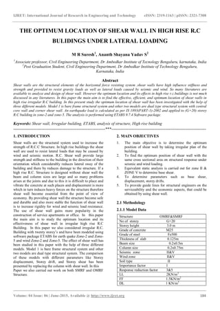
- 1. IJRET: International Journal of Research in Engineering and Technology eISSN: 2319-1163 | pISSN: 2321-7308 _______________________________________________________________________________________ Volume: 04 Issue: 06 | June-2015, Available @ http://www.ijret.org 184 THE OPTIMUM LOCATION OF SHEAR WALL IN HIGH RISE R.C BULIDINGS UNDER LATERAL LOADING M R Suresh1 , Ananth Shayana Yadav S2 1 Associate professor, Civil Engineering Department, Dr Ambedkar Institute of Tecnology Bengaluru, karnataka, India 2 Post Graduation Student, Civil Engineering Department, Dr Ambedkar Institute of Technology Bengaluru, Karnataka, India Abstract Shear walls are the structural elements of the horizontal force resisting system .shear walls have high influence stiffness and strength and provided to resist gravity loads as well as lateral loads caused by seismic and wind. So many literatures are available to analyze and design of shear wall. However the optimum location and its effects in high rise r.c.buildings is not much discussed in any literatures. In this paper the main aim is to find the effective, efficient, and optimum location of shear walls in high rise irregular R.C building. In this present study the optimum location of shear wall has been investigated with the help of three different models. Model 1 is bare frame structural system and other two models are dual type structural system with central core wall and corner shear wall. An earthquake load is calculated as per IS 1893(PART-1)-2002 and applied to (G+20) storey R.C building in zone-2 and zone-5. The analysis is performed using ETABS 9.7.4 Software package. Keywords: Shear wall, Irregular building, ETABS, analysis of structure, High rise building --------------------------------------------------------------------***---------------------------------------------------------------------- 1. INTRODUCTION Shear walls are the structural system used to increase the strength of R.C.C Structure. In high rise buildings the shear wall are used to resist lateral loads that may be caused by wind and seismic motion. R.C. Shear wall provide large strength and stiffness to the building in the direction of their orientation which considerably reduces lateral sway of the building and there by reduces damage to the structure. If a high rise R.C. Structure is designed without shear wall the beam and column sizes are large and so many problems arises at the joints and due to this it is difficult to place and vibrate the concrete at such places and displacement is more which in turn induces heavy forces on the structure therefore shear wall become essential from the point of view of economy. By providing shear wall the structure become safe and durable and also more stable the function of shear wall is to increase rigidity for wind and seismic load resistance. The use of shear wall gains more popularity in the construction of service apartments or office. In this paper the main aim is to study the optimum location and its effectiveness of shear wall in irregular high rise R.C Building. In this paper we also considered irregular R.C. Building with twenty storey’s and have been modeled using software package ETABS for earth quake Zone-2 and Zone- 5 and wind Zone-2 and Zone-5. The effect of shear wall has been studied in this paper with the help of three different models. Model 1 is bare frame structural system and other two models are dual type structural system. The comparison of these models with different parameters like Storey displacement, Storey drift, and Storey shear has been presented by replacing the column with shear wall. In this Paper we also carried out work on both SMRF and OMRF Structure. 2. MAIN OBJECTIVES 1. The main objective is to determine the optimum position of shear wall by taking irregular plan of the building. 2. To find the optimum position of shear wall with the same cross sectional area on structural response under seismic and wind loading. 3. Equivalent static analysis is carried out for zone II & ZONE V to determine base shear. 4. To determine parameters such as base shear, displacement, storey drifts. 5. To provide guide lines for structural engineers on the serviceability and the economic aspects, that could be obtained by using shear wall. 2.1 Methodology 2.1.1 Model Data Structure OMRF&SMRF No of storey G+20 Storey height 3.0 m Grade of concrete M25 Grade of steel Fe500 Thickness of slab 0.125m Beam size 0.2x0.5m Column size 0.2x0.75m Seismic zone II&V Wind zone II&V Soil type II Importance factor 1 Response reduction factor 3&5 LL 2KN/m2 FF 1.5KN/m2 DL 1 KN/m2
- 2. IJRET: International Journal of Research in Engineering and Technology eISSN: 2319-1163 | pISSN: 2321-7308 _______________________________________________________________________________________ Volume: 04 Issue: 06 | June-2015, Available @ http://www.ijret.org 185 2.2.2 The model is an irregular plan, the analysis is Carried out using a three-dimensional of detailed finite element models Fig -1: Plan with shear wall 2.2.3 Analysis of Structure ETABS software is used for the analysis of structure by Equivalent static Lateral Force Method for Zone II& Zone V. And the results obtained are tabulated for the study of behavior of structure. 2.2.4 Load Calculations The structure is subjected to three types of primary load as per the provision of IS Code of practice They are: Dead Load (From IS: 875-1987(Part I)) Live load (From IS: 875-1987(Part II)) Seismic Load (From IS: 1893-2002(part I)) 2.2.5 Method of analysis In the study, the analysis of the high rise structure is carried out for lateral loads using Equivalent Static Force Method. 2.2.6 Assumptions 1. Material: Concrete is assumed to behave linearly elastic. The modulus of elasticity Ec 5000 fc where the specified compressive strength of concrete fc is assumed equal to 25 Mpa. 2. Participating components: Only the primary structural components are assumed to participate in the overall behavior. The effects of secondary structural components and non structural components are assumed to be negligible: these include staircases, partitions, and openings. 3. Floor slabs: are assumed to be rigid diaphragm. 4. Constraints: Supporting bases of all structural models are fixed supports. 5. Loading: i. Gravity Loads: Dead load is taken as 1KN/m2 , the building weight and its content is considered in the dead load while, the live load is taken as 2 KN/ m2 . ii. Wind loads: will be developed according to Indian standard. 6. Wind loading : Vb =33 &50 Terrain category =2 Structure class= B Risk co-efficient K1=1 Topography K3= 1 Sample calculations Natural Time Period for Rigid System: For 20 Storey building T = 0.09h / √d =1.069s In X-Direction T=0.09X60/ (25.49)1/2=1.069s T=0.09h/√d=1.083s In Y-Direction T=0.09X60/ (24.82)1/2=1.083s 2.2.7 Storey V/S Drift According to clause 7.11.1 of IS 1893-part1:2002 and clause IS 456:2000 the maximum allowable drift is 0.04h and allowable displacement is (H/500) Where h is the storey height and H is the total height of the building. Graph1: Storey v/s Displacement for G+20 Table1: Maximum storey displacement in x-direction and y- direction for earth quake(EQ X&EQ Y) STOREY WITH OUT SHEAR WALL WITH CENTRAL CORE WALL WITH CENTRAL CORE WALL AND CORNER SHEAR WALL 20 X Y X Y X Y 155.6 151.1 107.3 108.3 81.6 81.4
- 3. IJRET: International Journal of Research in Engineering and Technology eISSN: 2319-1163 | pISSN: 2321-7308 _______________________________________________________________________________________ Volume: 04 Issue: 06 | June-2015, Available @ http://www.ijret.org 186 Graph 2: Storey v/s Displacement for G+20 Table 2: Maximum storey displacement in x-direction and y-direction for earth quake (EQ X&EQ Y) STOREY WITH OUT SHEAR WALL WITH CENTRAL CORE WALL WITH CENTRAL CORE WALL AND CORNER SHEAR WALL 20 X Y X Y X Y 246.9 485.7 231 231 175.7 173. 7 Graph 3: Storey v/s Displacement for G+20 Table 3: Maximum storey displacement in x-direction and y-direction for Wind (WX& WY) STOREY WITH OUT SHEAR WALL WITH CENTRAL CORE WALL WITH CENTRAL CORE WALL AND CORNER SHEAR WALL 20 X Y X Y X Y 39 79.9 32.3 36.9 25.5 27 Graph 4: Storey v/s Displacement for G+20 Table 4: Maximum storey displacement in x-direction and y-direction for Wind (WX& WY) STOREY WITH OUT SHEAR WALL WITH CENTRAL CORE WALL WITH CENTRAL CORE WALL AND CORNER SHEAR WALL 20 X Y X Y X Y 89.6 183.5 74.2 84.6 58.6 61.9 From this study we come to know that storey displacement is more in top storey compare to other storey.
- 4. IJRET: International Journal of Research in Engineering and Technology eISSN: 2319-1163 | pISSN: 2321-7308 _______________________________________________________________________________________ Volume: 04 Issue: 06 | June-2015, Available @ http://www.ijret.org 187 Graph 5: Storey v/s Drift for G+20 Table 5: Maximum storey drift STORE Y ZON E WITHO UT SHEAR WALL WITH CENTR AL CORE WALL WITH CENTRA L CORE WALL AND CORNER SHEAR WALL 08 2 0.003143 0.002158 0.001613 08 2 0.003069 0.002247 0.001607 09 2 0.003143 0.002207 0.001662 09 2 0.003062 0.002269 0.001651 10 2 0.003117 0.002227 0.001689 10 2 0.003033 0.002265 0.001674 11 2 0.003065 0.00222 0.001695 11 2 0.002977 0.002235 0.001678 Graph 6: Storey v/s Drift for G+20 Table 6: Maximum storey drift STORE Y ZON E WITHO UT SHEAR WALL WITH CENTR AL CORE WALL WITH CENTR AL CORE WALL AND CORNE R SHEAR WALL 07 5 0.001827 0.000926 0.000565 07 5 0.00993 0.002414 0.001434 09 5 0.004945 0.004753 0.003581 09 5 0.009817 0.004849 0.003534 10 5 0.004952 0.004796 0.003638 10 5 0.009652 0.004836 0.003581 11 5 0.004917 0.004783 0.00365 11 5 0.009404 0.00477 0.003587 Graph 7: Storey v/s Drift for G+20 Table 7: Maximum storey drift STORE Y ZON E WITHOU T SHEAR WALL WITH CENTRA L CORE WALL WITH CENTRA L CORE WALL AND CORNER SHEAR WALL 02 2 0.000711 0.000363 0.000241 02 2 0.00217 0.000514 0.000287 05 2 0.000852 0.000635 0.00046 05 2 0.001915 0.000802 0.000513 07 2 0.000835 0.000692 0.000516 07 2 0.001778 0.000831 0.000564 08 2 0.000816 0.000697 0.000526 08 2 0.001695 0.000821 0.00057 09 2 0.000791 0.000691 0.000532 09 2 0.001601 0.000798 0.000568
- 5. IJRET: International Journal of Research in Engineering and Technology eISSN: 2319-1163 | pISSN: 2321-7308 _______________________________________________________________________________________ Volume: 04 Issue: 06 | June-2015, Available @ http://www.ijret.org 188 Graph 8: Storey v/s Drift for G+20 Table 8: Maximum storey drift STOREY ZONE WITH OUT SHEAR WALL WITH CENTRAL CORE WALL WITH CENTRAL CORE WALL AND CORNER SHEAR WALL 02 5 0.001632 0.000834 0.000552 02 5 0.004983 0.00118 0.000659 05 5 0.001957 0.001457 0.001057 05 5 0.004396 0.001842 0.001179 07 5 0.001917 0.001588 0.001184 07 5 0.004081 0.001909 0.001294 08 5 0.001873 0.001601 0.001208 08 5 0.003892 0.001884 0.00131 09 5 0.001816 0.001587 0.00122 09 5 0.003675 0.001832 0.001305 Graph 9: Shear v/s Storey for G+20 Table 9: Maximum storey Shear in x-direction and y- direction for Earth Quake (EQX& EQY) STO REY WITH OUT SHEAR WALL WITH CENTRAL CORE WALL WITH CENTRAL CORE WALL AND CORNER SHEAR WALL 01 X Y X Y X Y 2903.1 1 2865. 58 2988. 57 2949. 94 299 0 2951 .35 Graph 10: Shear v/s Storey for G+20
- 6. IJRET: International Journal of Research in Engineering and Technology eISSN: 2319-1163 | pISSN: 2321-7308 _______________________________________________________________________________________ Volume: 04 Issue: 06 | June-2015, Available @ http://www.ijret.org 189 Table 10: Maximum storey Shear in x-direction and y- direction for Earth Quake (EQX& EQY) STOR EY WITH OUT SHEAR WALL WITH CENTRAL CORE WALL WITH CENTRAL CORE WALL AND CORNER SHEAR WALL 01 X Y X Y X Y 6375 .5 6293. 09 6454. 05 6370. 62 6457. 14 6373. 67 Graph 11: Shear v/s Storey for G+20 Table 11: Maximum storey Shear in x-direction and y- direction for Wind (WX& WY) STOR EY WITH OUT SHEAR WALL WITH CENTRAL CORE WALL WITH CENTRAL CORE WALL AND CORNER SHEAR WALL 01 X Y X Y X Y 1438 .7 1478. 15 1438 .7 1478. 15 1438 .7 1478. 15 Graph 12: Shear v/s Storey for G+20 Table 12: Maximum storey Shear in x-direction and y- direction for Wind (WX& WY) STOR EY WITH OUT SHEAR WALL WITH CENTRAL CORE WALL WITH CENTRAL CORE WALL AND CORNER SHEAR WALL 01 X Y X Y X Y 1438 .7 1478. 15 1438 .7 1478. 15 1438 .7 1478. 15 From this study we concluded that storey shear is more at the bottom storey compare to other storey. 3. CONCLUSION In this paper the study is carried out according to earthquake code book IS 1893[PART-I] 2002 and wind code book IS 875 [PART-I]-1987 and analysis is carried out by taking irregular plan of building [G+20] on medium [ZONE-II] and severe [ZONE-V] and soil [TYPE-II] and also in this paper the seismic analysis of irregular plan of building is done by both static earthquake and static wind analysis and also in this paper we also done comparison by providing shear wall at four edges with without shear wall in the irregular plan to determine the optimum position of shear wall. The following are the conclusion taken in this paper 1. The plan without shear wall gives more displacement and more drift compare to plan with shear wall along four edges. 2. Hence by providing shear wall along four edges we can reduce storey displacement, storey drift, storey shear and also we can increase strength and stiffness of the structure. 3. Hence we concluded that by providing shear wall along four edges is found to be optimum position of shear wall REFERENCES [1]. IS 1893[PART-I]-2002, “Criteria of earthquake resistance design of structures Bureau of Indian standards”, New Delhi. [2]. IS 875[PART-I]-1987, “Code of practice for design loads (other than earthquake) for buildings and structures. Dead loads unit weights of building materials and stored materials, Bureau of Indian standard, New Delhi. [3]. Bureau of Indian standard, IS-456(2000),”Plain and reinforced concrete code of practice”. [4]. IS 875[PART-II]-1987.Code of practice for design loads (other than earthquake) for building structures, imposed loads Bureau of Indian standard, New Delhi. [5]. Ravikanth Chittiprolu, Ramacharla Pradeep Kumar “Significance of shear wall in High-rise Irregular Buildings”. [6]. ETABS Nonlinear ver.9, Extended Three Dimensional analysis of building systems, computers and structures Inc. Berkeley, CAUSA,2006.
- 7. IJRET: International Journal of Research in Engineering and Technology eISSN: 2319-1163 | pISSN: 2321-7308 _______________________________________________________________________________________ Volume: 04 Issue: 06 | June-2015, Available @ http://www.ijret.org 190 BIOGRAPHIES Associate professor, Civil Engineering Department, has an working experience of 30yrs in Dr Ambedkar Institute of Tecnology Bengaluru Post Graduation Student, Civil Engineering Department in Dr Ambedkar Institute of Technology Bengaluru