Effect of seismic pounding between adjacent buildings and mitigation measures
•
1 like•884 views

1) The document analyzes seismic pounding between adjacent buildings constructed without sufficient separation. It considers models of a 10-story and 7-story building and analyzes displacement and impact force using SAP2000. 2) Mitigation measures like bracings and shear walls are found to reduce displacement by 50% compared to bare frames and keep displacement within the expansion joint. Shear walls perform better than bracings at reducing response. 3) Pounding damage can occur when adjacent buildings with different properties vibrate out of phase, exceeding the expansion joint gap. Taller buildings experience greater response than shorter ones.

Recommended
Recommended
More Related Content
What's hot
What's hot (20)
Similar to Effect of seismic pounding between adjacent buildings and mitigation measures
Similar to Effect of seismic pounding between adjacent buildings and mitigation measures (20)
More from eSAT Journals
More from eSAT Journals (20)
Recently uploaded
Recently uploaded (20)
Effect of seismic pounding between adjacent buildings and mitigation measures
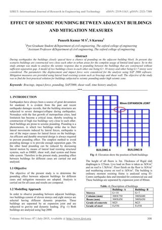
- 1. IJRET: International Journal of Research in Engineering and Technology eISSN: 2319-1163 | pISSN: 2321-7308 _______________________________________________________________________________________ Volume: 04 Issue: 07 | July-2015, Available @ http://www.ijret.org 208 EFFECT OF SEISMIC POUNDING BETWEEN ADJACENT BUILDINGS AND MITIGATION MEASURES Puneeth Kumar M S1 , S Karuna2 1 Post Graduate Student &Department of civil engineering, The oxford college of engineering 2 Assistant Professor &Department of civil engineering, The oxford college of engineering Abstract During earthquakes the buildings closely spaced have a chance of pounding on the adjacent building block. In present day scenario buildings are constructed very close each other in urban areas for the complete usage of limited land space. So in this study attempt was made to analyse the seismic response due to pounding between the buildings that are constructed without sufficient separation gap. A model of two buildings closes to each other one being G+ 10 storey and other being G+7 storey were considered. The parameters like displacement and impact force were considered for the analysis using SAP 2000 software. Mitigation measures are provided using lateral load resisting system such as bracings and shear wall. The objective of the study was to find the best practical solution for buildings subjected to seismic pounding under high seismic zone. Keywords: Bracings, impact force, pounding, SAP2000, shear wall, time history analysis. --------------------------------------------------------------------***------------------------------------------------------------------ 1. INTRODUCTION Earthquakes have always been a source of great devastation for mankind. It is evident from the past and recent earthquake damages records, that the building structures are subjected to severe damages/collapse during earthquakes. Nowadays with the fast growth of metropolitan cities, land limitation has become a critical issue, thereby resulting in construction of high rise buildings very close to each other. Such buildings are prone to seismic pounding. Pounding is a phenomenon, in which two buildings strike due to their lateral movements induced by lateral forces, earthquake is one of the major causes for lateral forces on the buildings. An efficient and durable structural design is always required to prevent pounding effect. The simplest method to avoid pounding damage is to provide enough separation gaps. On the other hand pounding can be reduced by decreasing lateral motion by means of lateral load resisting structural systems, such as SMRF, shear wall, dual system and frame tube system. Therefore in the present study, pounding effect between buildings for different cases are carried out and analysed. 1.1 Objective The objective of the present study is to determine the pounding effect between adjacent buildings for different cases and mitigation measures are adopted. Analysis is carried out for all cases and results are compared. 1.2 Modelling Approach In order to observe pounding between adjacent buildings, two buildings consist of eleven storeys and eight storeys are selected having different dynamic properties. These buildings are separated by an expansion joint and are subjected to gravity and dynamic loading. (Fig -1) Both buildings are analysed using Sap 2000. Fig -1: Elevation show the position of both buildings The height of all floors is 3m. Thickness of Rigid slab diaphragm is 125mm. Live load on floor is taken as 3kN/m2 and on roof is 1.5kN/m2 . Floor finish on the floor is 1kN/m2 and weathering course on roof is 1kN/m2 . The building is ordinary moment resisting frame is analysed using El- Centro earthquake data and intended for commercial use and These buildings are separated by expansion joint of 80mm. Table -1: Description of buildings Building- A Building- B Storeys G+10 G+7 Column (mm) 300X750 300X600 Beam (mm) 300X450 300X450 Grade of concrete M25 M25 Grade of steel Fe550 Fe550
- 2. IJRET: International Journal of Research in Engineering and Technology eISSN: 2319-1163 | pISSN: 2321-7308 _______________________________________________________________________________________ Volume: 04 Issue: 07 | July-2015, Available @ http://www.ijret.org 209 1.2.1 Gap Element Model In order to calculate impact force between the adjacent buildings during seismic excitation, a gap element needs to connect between the structures. Gap elements have 2 nodes I and j, expansion joint of structures is specified in gap element. The stiffness of the gap element is generally adopted as 102 to 104 time the stiffness of the adjacent connected element, usually gap element only active in compression phase and it becomes inactive in tension phase. The gap element is active when the gap becomes zero as shown in Fig –2 and gap element connected between adjacent buildings is shown in Fig -3. Fig -2: Model of gap element Fig - 3: Shows connection of gap element The pounding effect is considered for the following different cases. (i) Adjacent buildings at same floor levels (ii) Adjacent buildings with different floor level (iii) Adjacent buildings with different floor level( floor to mid column) (iv) Buildings with Setback of 4m 2. ANALYSIS AND RESULTS The buildings are analysed under time history data of elcentro which is to be known as above average earthquake, the displacement of buildings were observed with respect to time. For all the cases considered, pounding observance is done for the worst condition by taking positive displacement of G+10 story and Negative displacement of G+7 story due to their different dynamic characteristics. 2.1 Adjacent Buildings at Same Floor Levels In this case, two adjacent buildings are at same floor level (Fig -4). Fig -5shows that maximum negative displacement of G+7 story building at seventh floor level is 45.48mm at 3.52 sec and maximum positive displacement for G+10 story building is 105.69mm at 3.52 sec. From Fig – 5 it is also noticed that maximum out of phase movement of both building at 3.52 sec is (105.69+45.48)-80= 71.17mm which is greater than expansion joint.. Due to this out of phase moment, impact force is created in the gap element. Fig -6 indicates the maximum impact force of 2300KN created between the adjacent buildings. Fig -4: Elevation of buildings with same floor level
- 3. IJRET: International Journal of Research in Engineering and Technology eISSN: 2319-1163 | pISSN: 2321-7308 _______________________________________________________________________________________ Volume: 04 Issue: 07 | July-2015, Available @ http://www.ijret.org 210 Fig -5: Displacement vs time graph of both buildings of same floor level at seventh floor level Fig -6: Impact force vs time graph of both buildings of same floor level at seventh floor level 2.2 Adjacent Buildings with Different Floor Level In this case, two adjacent buildings are at different floor level (Fig -7). Fig -8 shows that maximum negative displacement of G+7 story building at seventh floor level is 45.48mm at 3.52 sec and maximum positive displacement for G+10 story building is 95.64mm at 3.52 sec. From Fig – 8 it is also noticed that maximum out of phase movement of both building at 3.52 sec is (95.64+45.48)-80= 61.11mm which is greater than expansion joint. Due to this out of phase moment impact force is created in the gap element, Fig -9 indicates the maximum impact force of 1250KN created between the adjacent buildings. Fig -7: Elevation of buildings at different floor level
- 4. IJRET: International Journal of Research in Engineering and Technology eISSN: 2319-1163 | pISSN: 2321-7308 _______________________________________________________________________________________ Volume: 04 Issue: 07 | July-2015, Available @ http://www.ijret.org 211 Fig -8: Displacement vs time graph of both buildings of different floor level at seventh floor level Fig -9: Impact force vs time graph of both buildings of different floor level at seventh floor level 2.3 Adjacent Buildings with Different Floor Level (Floor to Mid Column) In this case two adjacent two buildings with different floor level (with floor to mid column) are considered (Fig -10). It is observed that from Fig -11 maximum negative displacement of G+7 story building at seventh floor level is 45.48mm at 3.52 sec and maximum positive displacement for G+10 story building is 100.665 mm at 3.62 sec. From Fig - 11 it is noticed that maximum out of phase movement of both building at 3.62 sec is (100.665+45.48)-80= 66.145mm which is greater than expansion joint. Due to this out of phase moment impact force is created in the gap element, Fig -12indicate the maximum impact force of 2200 KN created between the adjacent buildings. Fig -10: Elevation of buildings at different floor level (floor to mid column)
- 5. IJRET: International Journal of Research in Engineering and Technology eISSN: 2319-1163 | pISSN: 2321-7308 _______________________________________________________________________________________ Volume: 04 Issue: 07 | July-2015, Available @ http://www.ijret.org 212 Fig -11: Displacement vs time graph of both buildings of different floor level (floor to mid column) at seventh floor level Fig -12:Impact force vs time graph of both buildings of different floor level (floor to mid column) at seventh floor level 2.4 Buildings with Setback of 4m In this case, the adjacent buildings are considered with a setback of 4m (Fig -13). Fig -14 shows that maximum negative displacement of G+7 story building at seventh floor level is 45.48mm at 3.52 sec and maximum positive displacement for G+10 story building is 105.69 mm at 3.52 sec. It is noticed that maximum out of phase movement of both building at 3.52 sec is (105.69+45.48)-80= 71.17mm which is greater than expansion joint. Due to this out of phase moment impact force is created in the gap element, Fig - 15indicate that the maximum impact force of 2220KN created between the adjacent buildings. Fig -13: Plan of buildings with setback
- 6. IJRET: International Journal of Research in Engineering and Technology eISSN: 2319-1163 | pISSN: 2321-7308 _______________________________________________________________________________________ Volume: 04 Issue: 07 | July-2015, Available @ http://www.ijret.org 213 Fig -14: Displacement vs time graph of both buildings at setback at seventh floor level Fig -15: Impact force vs time graph of both buildings at setback at seventh floor level 3. MITIGATION MEASURES To avoid pounding effect, generally lateral load resisting systems are used. In this present study bracings (inverted V type) and shear wall are provide to reduce the effect of pounding. 3.1 Buildings with Bracings The displacement of building with bracings for different cases is presented in table -2. It is noted that Maximum Positive displacement of eleven storey building and Maximum Negative displacement of eight storey is within the expansion joint in all the cases. The graphical representation of displacement of buildings with and without bracings for all the cases is shown in Fig - 17 to Fig - 20. It is observed that, the displacement of buildings with bracings is reduced 50% than buildings when compared with bare frame. Fig -16: Elevation of buildings with bracings
- 7. IJRET: International Journal of Research in Engineering and Technology eISSN: 2319-1163 | pISSN: 2321-7308 _______________________________________________________________________________________ Volume: 04 Issue: 07 | July-2015, Available @ http://www.ijret.org 214 Fig -17: Comparison of displacement of buildings with same floor level Fig -18: Comparison of displacement of buildings with different floor level Fig -19: Comparison of displacement of buildings with different floor level (floor to mid column) Fig -20: Comparison of displacement of buildings with setback Table -2: Displacement of buildings with bracings for different cases Sl. no Models Displacement of building A (mm) Displacement of building B (mm) Total displacement (mm) 1 Same floor level 37.96 14.28 52.24 2 Different floor level 31.75 14.28 46.03 3 Different floor level (floor to mid column) 34.855 14.28 49.135 4 Setback 37.95 14.28 52.23 3.2 Buildings with Shear Wall By providing Shear walls the lateral displacements of buildings can be reduced. A RC wall of 0.15m thickness can replace masonry wall of building. It is noted that Maximum Positive displacement of eleven storey building and Maximum Negative displacement of eight storey is within the expansion joint in all the cases. The displacement of building with shear wall for different cases is presented in table 3. The graphical representation of displacement of buildings with and without shear wall is shown from Fig – 22 to Fig - 25.The displacement of buildings with shear wall is reduced more than 50% compared to buildings without shear wall.
- 8. IJRET: International Journal of Research in Engineering and Technology eISSN: 2319-1163 | pISSN: 2321-7308 _______________________________________________________________________________________ Volume: 04 Issue: 07 | July-2015, Available @ http://www.ijret.org 215 Fig – 21: Elevation of buildings with shear wall Fig -22: Comparison of displacement of buildings with same floor level Fig -23: Comparison of displacement of buildings with different floor level Fig - 24: Comparison of displacement of buildings with different floor level (floor to mid column) Fig -25: Comparison of displacement of buildings with setback
- 9. IJRET: International Journal of Research in Engineering and Technology eISSN: 2319-1163 | pISSN: 2321-7308 _______________________________________________________________________________________ Volume: 04 Issue: 07 | July-2015, Available @ http://www.ijret.org 216 Table -3: Displacement of buildings with shear wall for different cases Sl no Models Displacement of building A (mm) Displacement of building B (mm) Total displacement (mm) 1 Same floor level 27.05 6.23 33.28 2 Different floor level 22.27 6.23 28.5 3 Different floor level (floor to mid column) 24.66 6.23 30.89 4 Setback 27.04 6.23 33.27 4. CONCLUSION During strong earthquakes, adjacent buildings without proper separation gap are affected by pounding. When comparing all the cases of study, adjacent buildings with same floor level, different floor level and set back, out of phase movement is greater than expansion joint which creates impact force Adjacent buildings, with different dynamic properties, vibrate out of phase leading to pounding damage. The maximum response (displacement) is more in taller buildings than the shorter one. Buildings with shear wall are more effective than with bracings. REFERENCES [1]. Pradeep Kumar R, Kiran Kumar Reddy K and Chandra Sekhara Reddy T (2014), “Pounding problems in urban areas” [2]. H.L.Suresh, Ravindranatha, Shivananda S.M. and Tauseef M Honnyal, (2014), “A study of seismic pounding between adjacent buildings”. [3]. Pradeep Kumar Ramancharla and ChennaRajaram (2012), “Three dimensional modeling of pounding”. [4]. H.S.Vidyadhara and KhajaAfrozJama“Seismic pounding of multistoried buildings”. [5]. IS 1893-2002(Part-1), “Criteria for Earthquake resistant design of structures, General provisions and buildings”, Bureau of Indian Standards, New Delhi [6]. IS 456:2000, “Plain and Reinforced concrete - Code of practice”, Bureau of Indian Standards, New Delhi. [7]. “SAP2000 Integrated Finite Elements Analysis and Design of Structures” tutorial manual. [8]. “SAP2000 CSi Analysis Reference Manual”