Downloaded 140 times


![P a g e 60 | 92
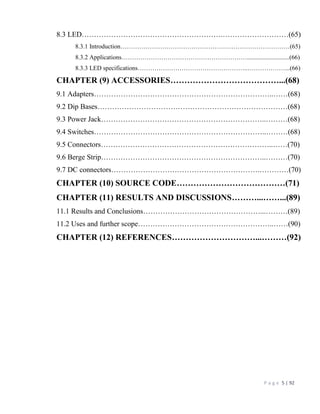
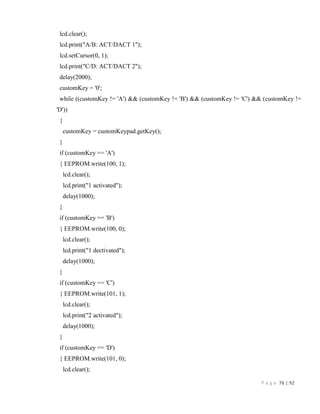
CHAPTER (8) COMPONENTS
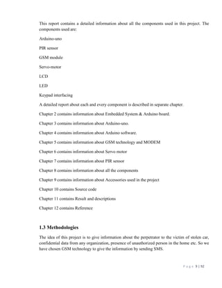
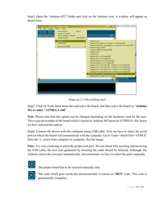
8.1 Capacitor
8.1.1 Introduction
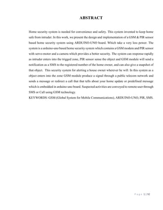
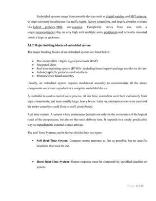
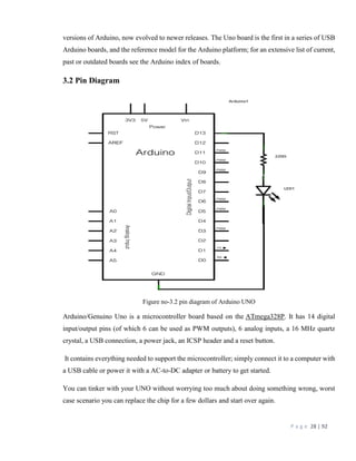
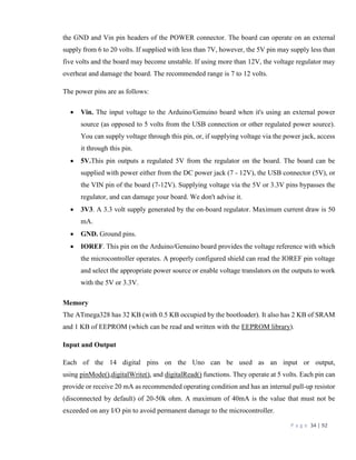
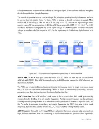
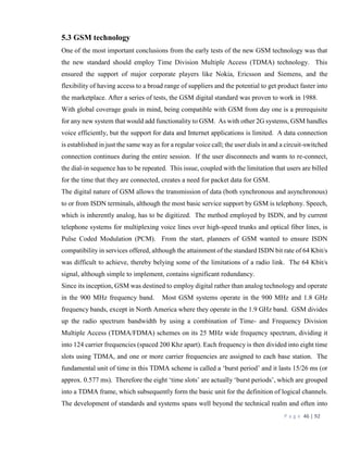
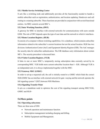
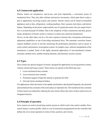
The capacitor's function is to store electricity, or electrical energy. The capacitor also functions as
a filter, passing alternating current (AC), and blocking direct current (DC). This symbol ( )is
used to indicate a capacitor in a circuit diagram. The capacitor is constructed with two electrode
plates facing each other but separated by an insulator.
When DC voltage is applied to the capacitor, an electric charge is stored on each electrode.
While the capacitor is charging up, current flows. The current will stop flowing when the capacitor
has fully charged.
8.1.2 Actual Capacitance
This is a measure of a capacitor’s ability to store charge. A large capacitance means that more
charge can be stored. It is measured in farad, F. 1F is very large, so prefixes are used to show the
smaller values.
Three prefixes are used, u (micron), n (Nano), and p (Pico).
1uf=10-6
f
1nf=10-9
f
1pf=10-12
f
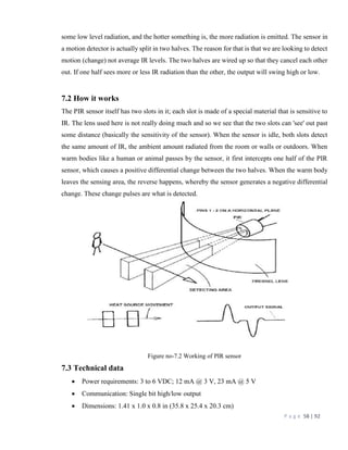
Sometimes, a three-digit code is used to indicate the value of a capacitor. There are two
ways in which the capacitance can be written one uses letters and numbers, the other uses only
numbers. In either case, there are only three characters used. [10n] and [103] denote the same value
of capacitance.
The method used differs depending on the capacitor supplier. In the case that the value is
displayed with the three-digit code, the 1st and 2nd digits from the left show the 1st figure and the
2nd figure, and the 3rd digit is a multiplier which determines how many zeros are to be added to
the capacitance. Pico farad (pF) units are written this way.
For example, when the code is [103], it indicates 10 x 103, or 10,000pF = 10 nano-farad
(nF) = 0.01 microfarad (µF).
If the code happened to be [224], it would be 22 x 104 = or 220,000pF = 220nF = 0.22µF.
Values under 100pF are displayed with 2 digits only. For example, 47 would be 47pF.
The capacitor has an insulator (the dielectric) between 2 sheets of electrodes. Different kinds of
capacitors use different materials for the dielectric.](https://image.slidesharecdn.com/finalprojectreport-161008191804/85/Home-security-system-60-320.jpg)
![P a g e 71 | 92
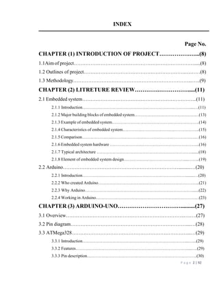
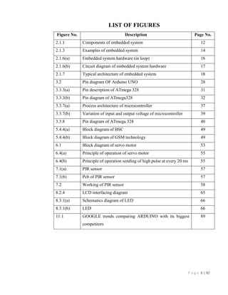
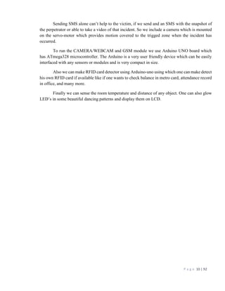
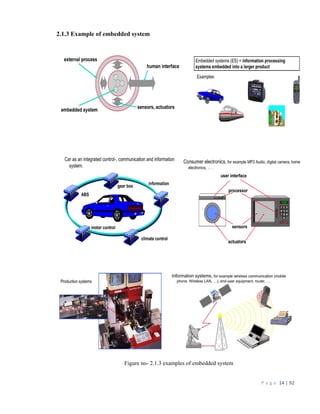
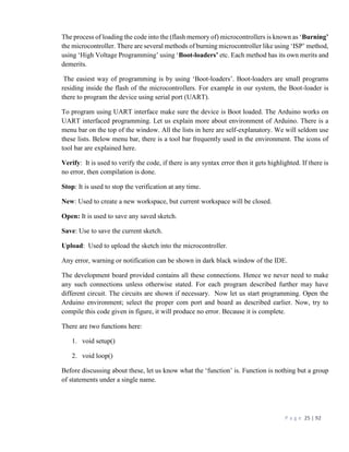
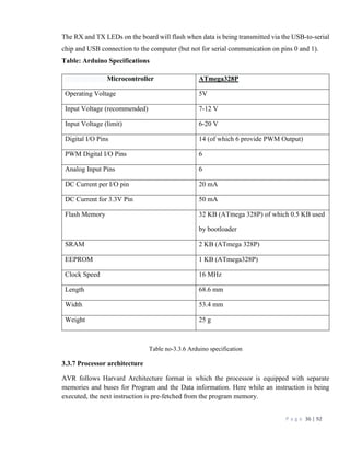
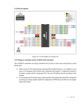
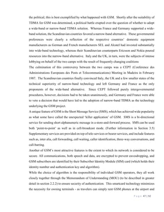
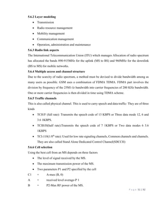
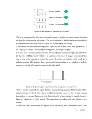
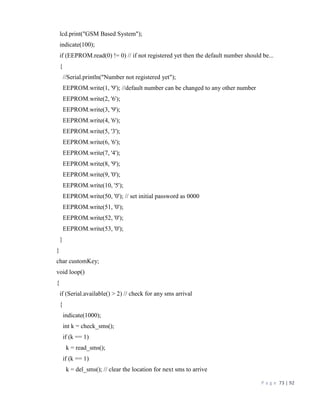
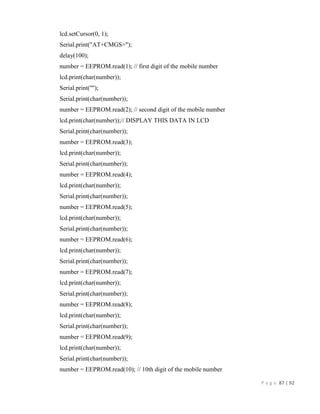
CHAPTER (10) SOURCE CODE
#include <Servo.h>
#include <Key.h>
#include <Keypad.h>
#include <LiquidCrystal.h>
#include <EEPROM.h>
#define led_pin 13
#define pir1 11
#define pir2 12
#define servoPin 10
const byte ROWS = 4; //four rows
const byte COLS = 4; //four columns
//define the cymbols on the buttons of the keypads
char hexaKeys[ROWS][COLS] = {
{'D', '#', '0', '*'},
{'C', '9', '8', '7'},
{'B', '6', '5', '4'},
{'A', '3', '2', '1'}
};
byte colPins[COLS] = {2, 3, 4, 5}; //connect to the row pinouts of the keypad
byte rowPins[ROWS] = {6, 7, 8, 9};
Servo myservo;
Keypad customKeypad = Keypad( makeKeymap(hexaKeys), rowPins, colPins, ROWS, COLS);
LiquidCrystal lcd(14, 15, 16, 17, 18, 19);
boolean data = false;
char sms[50];
byte sms_length = 0;
int user = -1;
byte temp_mob[10];
String sms2send = "Your Number has been Registered";
boolean previousState = false;](https://image.slidesharecdn.com/finalprojectreport-161008191804/85/Home-security-system-71-320.jpg)
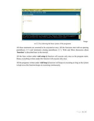
![P a g e 77 | 92
lcd.print("2 dectivated");
delay(1000);
}
}
int changePassword()
{
char value[4];
int n = 0;
lcd.clear();
lcd.print("Enter new PSW");
lcd.setCursor(0, 1);
while (1)
{
char customKey = customKeypad.getKey();
if (customKey)
{
value[n] = customKey;
lcd.print('*');
n++;
if (n == 4)
{ EEPROM.write(50, value[0]);
EEPROM.write(51, value[1]);
EEPROM.write(52, value[2]);
EEPROM.write(53, value[3]);
lcd.print("->");
lcd.print(value[0]);
lcd.print(value[1]);
lcd.print(value[2]);
lcd.print(value[3]);
delay(1000);
return 1;
}](https://image.slidesharecdn.com/finalprojectreport-161008191804/85/Home-security-system-77-320.jpg)
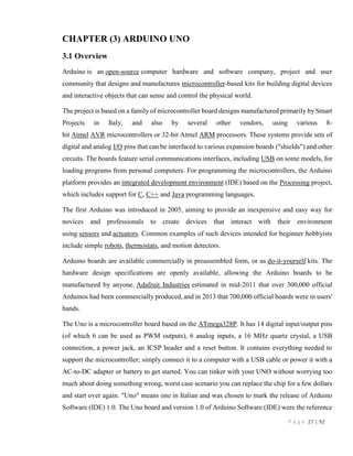
![P a g e 78 | 92
}
}
}
int checkPassword() // return 1 for master 2 for slave and 0 for none
{
char value[4];
int n = 0;
lcd.clear();
lcd.print("Enter password");
lcd.setCursor(0, 1);
while (1)
{
char customKey = customKeypad.getKey();
if (customKey)
{
value[n] = customKey;
lcd.print(value[n]);
//lcd.print('*');
n++;
if (n == 4)
{
if ( (value[0] == EEPROM.read(50)) && (value[1] == EEPROM.read(51)) && (value[2] ==
EEPROM.read(52)) && (value[3] == EEPROM.read(53)))
{
lcd.print("matched");
delay(1000);
return 1;
}
else
{
return 0;
}](https://image.slidesharecdn.com/finalprojectreport-161008191804/85/Home-security-system-78-320.jpg)
![P a g e 79 | 92
}
}
}
}
byte search_modem() // will keep on searching for modem unless it is found
{
//Serial.println("Searching the Modem");
lcd.clear();
lcd.print(" Testing modem....");
lcd.setCursor(0, 1);
char ch[50];
int n = 0;
Serial.println("AT"); // activate the modem
delay(100);
Serial.println("AT"); // activate the modem
Serial.println("AT"); // activate the modem
delay(100);
while (1)
{
if (Serial.available())
{
ch[n] = Serial.read();
if ((ch[n - 1] == 'O') && (ch[n] == 'K')) //ok if modem is there
{
lcd.print("Testing Done...");
return 1;
}
n++;
if (n > 40)
n = 0;
}
else {](https://image.slidesharecdn.com/finalprojectreport-161008191804/85/Home-security-system-79-320.jpg)
![P a g e 80 | 92
lcd.clear();
lcd.print("Connect Modem");
lcd.setCursor(0, 1);
Serial.println("AT"); // activate the modem
delay(1000);
}
}
}// search ends
byte configure_modem() // initial configuration of modem
{
char ch[50];
int n = 0;
lcd.clear();
lcd.print("Configuring Modem....");
Serial.println("AT");
delay(10);
Serial.println("ATE0"); // turn off echo
delay(500);
Serial.println("ATE0"); // turn off echo
delay(500);
Serial.println("ATE0"); // turn off echo
delay(500);
Serial.println("ATE0"); // turn off echo
delay(500);
Serial.println("AT+CMGF=1"); //set the sms format as text
delay(500);
Serial.println("AT+CNMI=2,1,0,0,1"); // indicates the arrival of sms
delay(1000);
Serial.flush();
Serial.println("AT");
while (1)
{](https://image.slidesharecdn.com/finalprojectreport-161008191804/85/Home-security-system-80-320.jpg)
![P a g e 81 | 92
if (Serial.available())
{
ch[n] = Serial.read();
if ((ch[n - 1] == 'O') && (ch[n] == 'K')) //ok if modem is there
{
lcd.clear();
lcd.print("Cofigured.....");
return 1;
}
n++;
if (n > 40)
n = 0;
}
else
{
n = 0;
lcd.clear();
lcd.print("Confi Failed..");
lcd.setCursor(0, 1);
lcd.print("Please Reset");
}
}
}
int check_sms()
{
char ch[20];
int n = 0;
byte flag = 0; // indicates the arrival of sms
if (Serial.available())
{
delay(1000);// wait for all serial data to arrive.](https://image.slidesharecdn.com/finalprojectreport-161008191804/85/Home-security-system-81-320.jpg)
![P a g e 82 | 92
while (Serial.available()) // read all serial data.
{
ch[n] = Serial.read();
if ((ch[n - 3] == 'C') && (ch[n - 2] == 'M') && (ch[n - 1] == 'T') && (ch[n] == 'I'))
{
flag = 1;
lcd.clear();
lcd.print("SMS Arrived");
}
n++;
if (n > 19)
n = 0;
}
if (flag == 1)
return 1;
else
{
Serial.flush(); // clear unuseful data
return 0;
}
}
}
byte read_sms()
{
char ch[100];
int n = 0;
int m = 0;
int digit = 0;
byte temp = 0; // to read the sms
byte temp1 = 0; // to read the mobile number
lcd.clear();
lcd.print("Reading SMS....");](https://image.slidesharecdn.com/finalprojectreport-161008191804/85/Home-security-system-82-320.jpg)
![P a g e 83 | 92
lcd.setCursor(0, 1);
Serial.println("AT+CMGR=1"); // command to read the sms at loction 1
while (1)
{
if (Serial.available())
{
ch[n] = Serial.read();
// //Serial.print(ch[n]);
if ((ch[n - 1] == 'O') && (ch[n] == 'K')) // successful reading of SMS
{
for (int i = 0; i <= n; i++) // extract sms part
{
if (temp1 == 2) // + sign arrives with second + sign
{
temp_mob[digit] = ch[i + 2]; // digits after +91
digit++;
if (digit == 10)
temp1 = 0; // reading of mobile number finished
}
if (ch[i] == '*') // terminating character stop reading
{
temp = 0;
sms_length = m - 1;
}
if (temp == 1) // store sms part in sms variable
{
sms[m] = ch[i];
m++;
}
if (ch[i] == '#') //starting character start reading
temp = 1;](https://image.slidesharecdn.com/finalprojectreport-161008191804/85/Home-security-system-83-320.jpg)
![P a g e 84 | 92
if (ch[i] == '+') // mobile number starts with +91
temp1++;
}// end of for loop
//Serial.print("mobile number ");
for (int i = 0; i <= 9; i++)
{
//Serial.print(char(temp_mob[i]));
}
register_user(); //function to register the user.
lcd.print("Reading Successful..");
return 1;
}
n++;
if (n >= 100)
n = 0;
}
}
}
byte del_sms()
{
char ch[20];
int n = 0;
lcd.clear();
lcd.print("Removing SMS..");
lcd.setCursor(0, 1);
Serial.println("AT+CMGD=1"); // command to delete the sms at loction 1
while (1)
{
if (Serial.available())
{
delay(1000);
while (Serial.available())](https://image.slidesharecdn.com/finalprojectreport-161008191804/85/Home-security-system-84-320.jpg)
![P a g e 85 | 92
{
ch[n] = Serial.read();
if ((ch[n - 1] == 'O') && (ch[n] == 'K'))
{
lcd.print("SMS Deleted..");
return 1;
}
n++;
if (n > 19)
n = 0;
}
lcd.print("Error...");
return 0;
}
}
}
void indicate(int d) // indicate with led and buzzer
{
digitalWrite(led_pin, HIGH);
delay(d);
digitalWrite(led_pin, LOW);
}
int register_user() // register user/ save number in EEPROM
{
//Serial.print("sms");
//Serial.println(sms);
if ((sms[0] == 'A') && (sms[1] == 'B') && (sms[2] == 'C'))
{
lcd.clear();
lcd.println("Registration....");
EEPROM.write(0, 0); // to indicate that the user has been registered](https://image.slidesharecdn.com/finalprojectreport-161008191804/85/Home-security-system-85-320.jpg)
![P a g e 86 | 92
delay(100);
EEPROM.write(1, sms[3]);
delay(100);
EEPROM.write(2, sms[4]);
delay(100);
EEPROM.write(3, sms[5]);
delay(100);
EEPROM.write(4, sms[6]);
delay(100);
EEPROM.write(5, sms[7]);
delay(100);
EEPROM.write(6, sms[8]);
delay(100);
EEPROM.write(7, sms[9]);
delay(100);
EEPROM.write(8, sms[10]);
delay(100);
EEPROM.write(9, sms[11]);
delay(100);
EEPROM.write(10, sms[12]);
delay(100);
sms2send = "This number is registered";
send_sms();
}
}
byte send_sms()
{
char ch[20];
int n = 0;
byte number = 0;
lcd.clear();
lcd.print("Sending SMS..");](https://image.slidesharecdn.com/finalprojectreport-161008191804/85/Home-security-system-86-320.jpg)
![P a g e 88 | 92
lcd.print(char(number));
Serial.print(char(number));
Serial.println('"');
delay(1000);
Serial.println(sms2send);
delay(100);
Serial.print(char(26)); // ascii code for ctrl^z
while (1)
{
if (Serial.available())
{
ch[n] = Serial.read();
//Serial.print(char(ch[n]));
if ((ch[n - 3] == 'C') && (ch[n - 2] == 'M') && (ch[n - 1] == 'G') && (ch[n] == 'S'))
{
lcd.print("Sent");
delay(1000);
Serial.flush();// clear all other data
return 1;
}
if ((ch[n - 3] == 'E') && (ch[n - 2] == 'R') && (ch[n - 1] == 'R') && (ch[n] == 'O'))
{
lcd.print("Error");
delay(1000);
Serial.flush();// clear all other data
return 0;
}
n++;
if (n >= 20)
n = 0;
}
}](https://image.slidesharecdn.com/finalprojectreport-161008191804/85/Home-security-system-88-320.jpg)


The document details the design and implementation of a GSM and PIR sensor-based home security system utilizing an Arduino Uno board, aiming to enhance home safety and convenience. Upon detection of an intruder, the system sends a notification via SMS to the homeowner and can capture a snapshot of the intruder. The report also provides extensive information on the components involved, including the Arduino board, GSM technology, and other hardware used in the project.


![Industrial presentation [2].pdf Robotics and ebedded system](https://cdn.slidesharecdn.com/ss_thumbnails/industrialpresentation2-251214110944-d4e0ee7a-thumbnail.jpg?width=640&height=640&fit=bounds)


