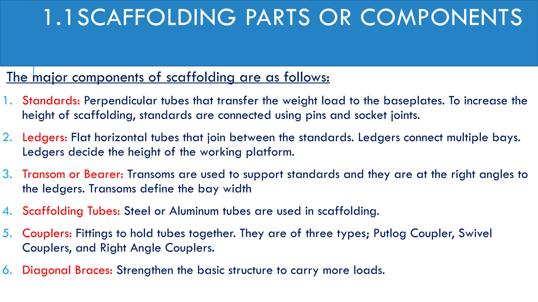
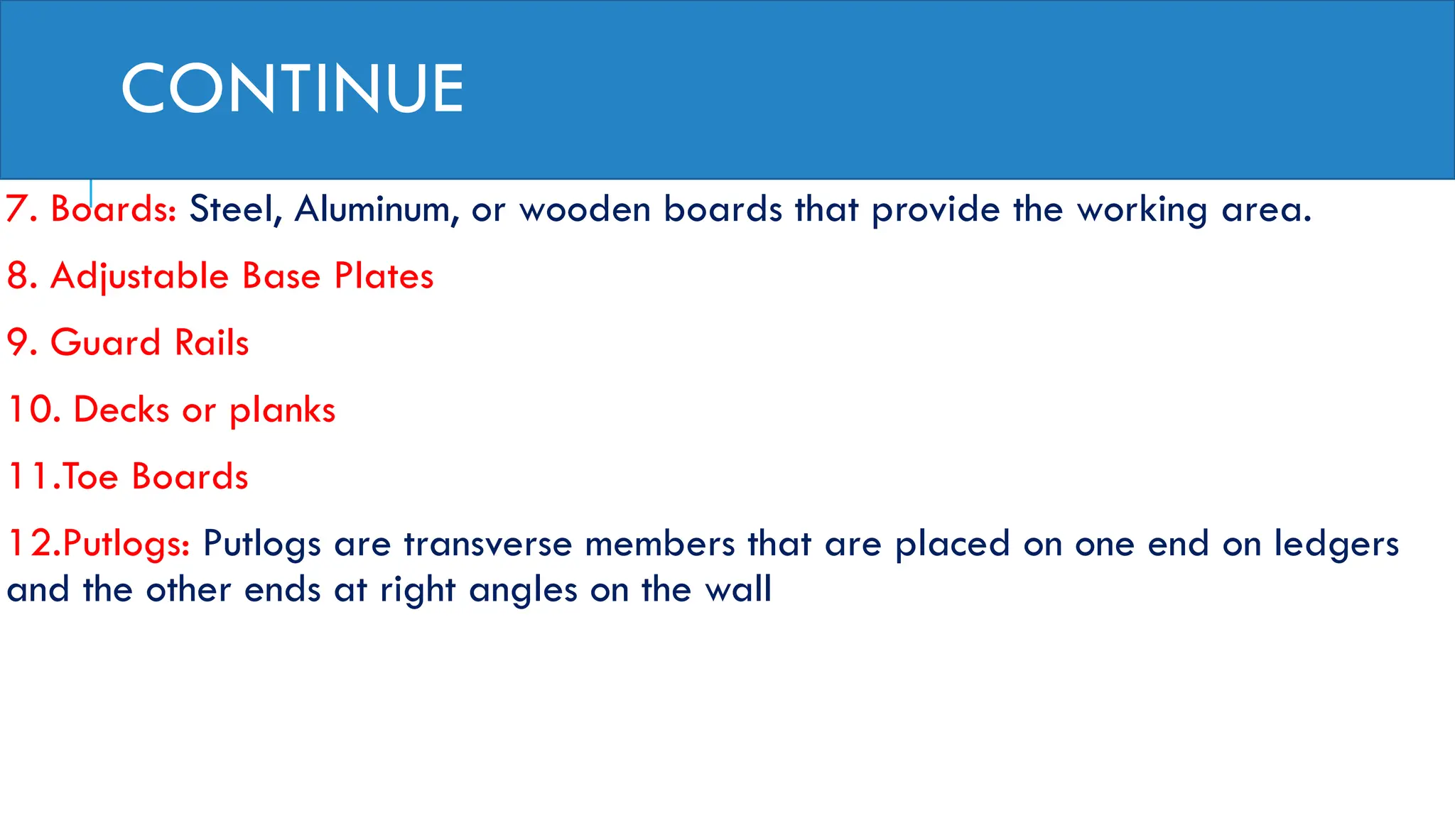
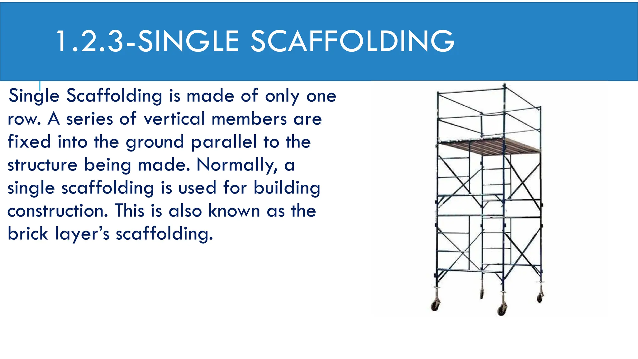
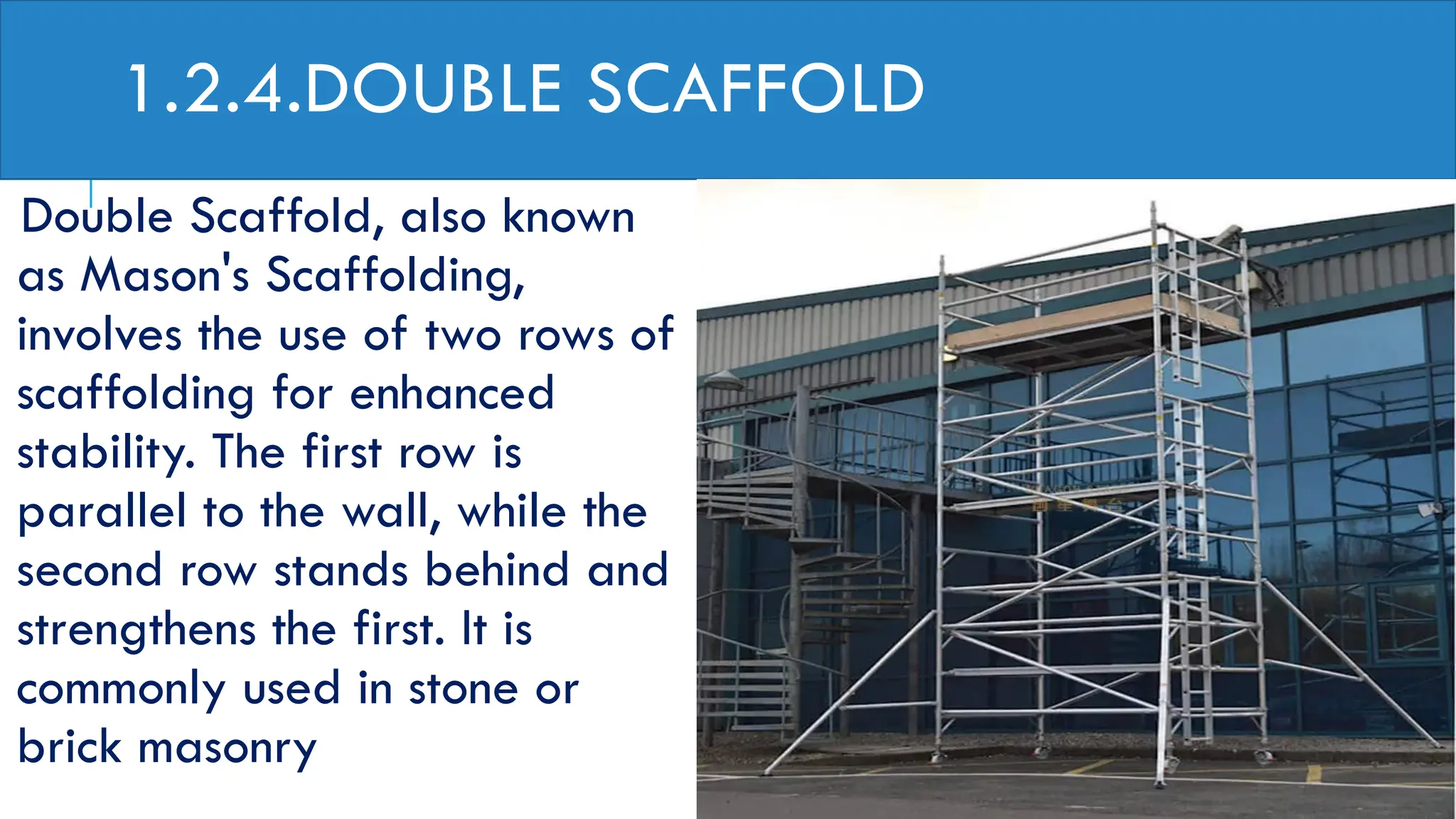
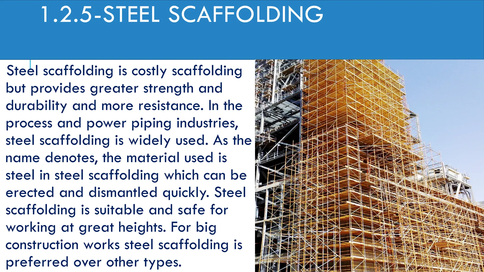
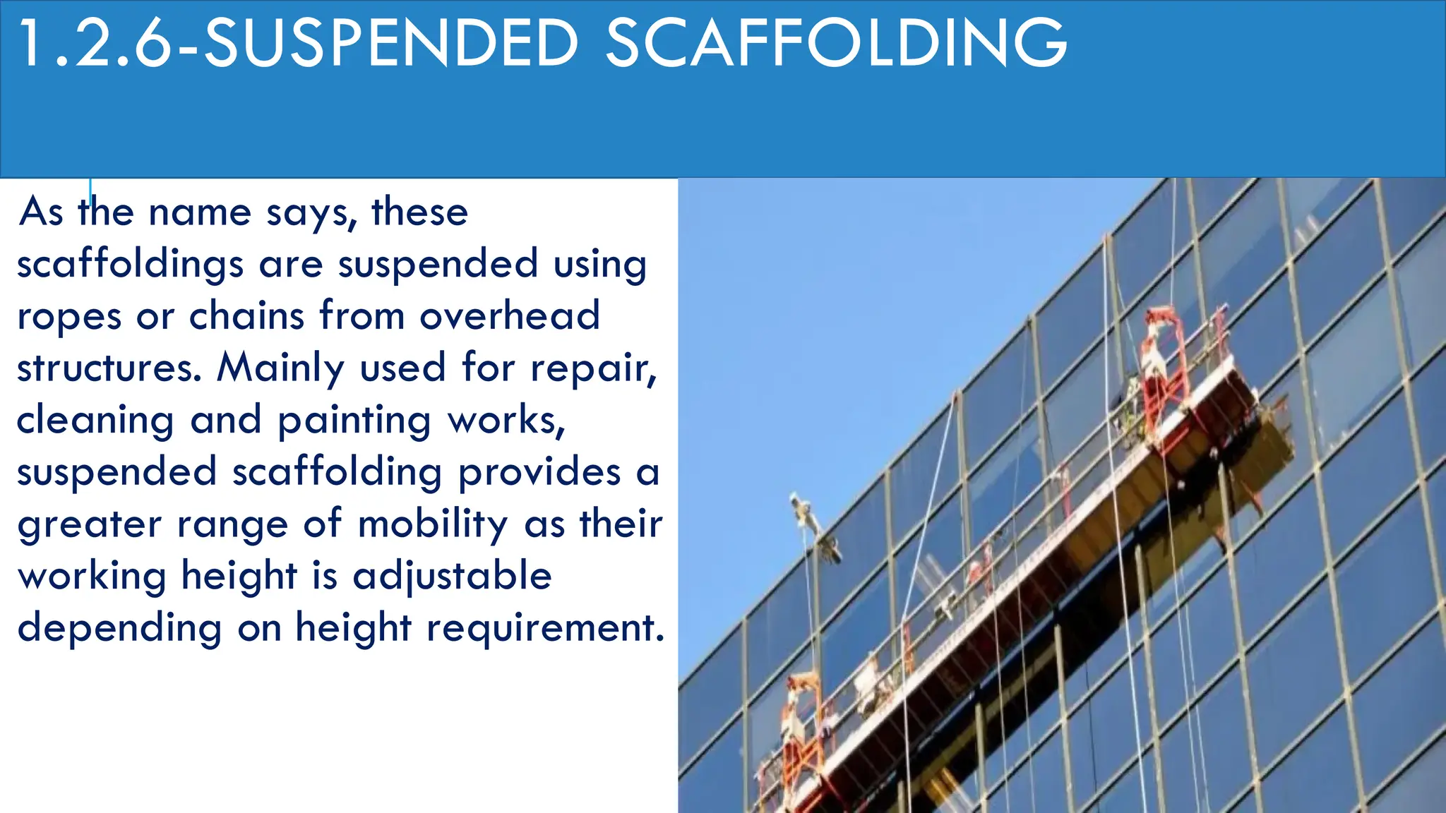
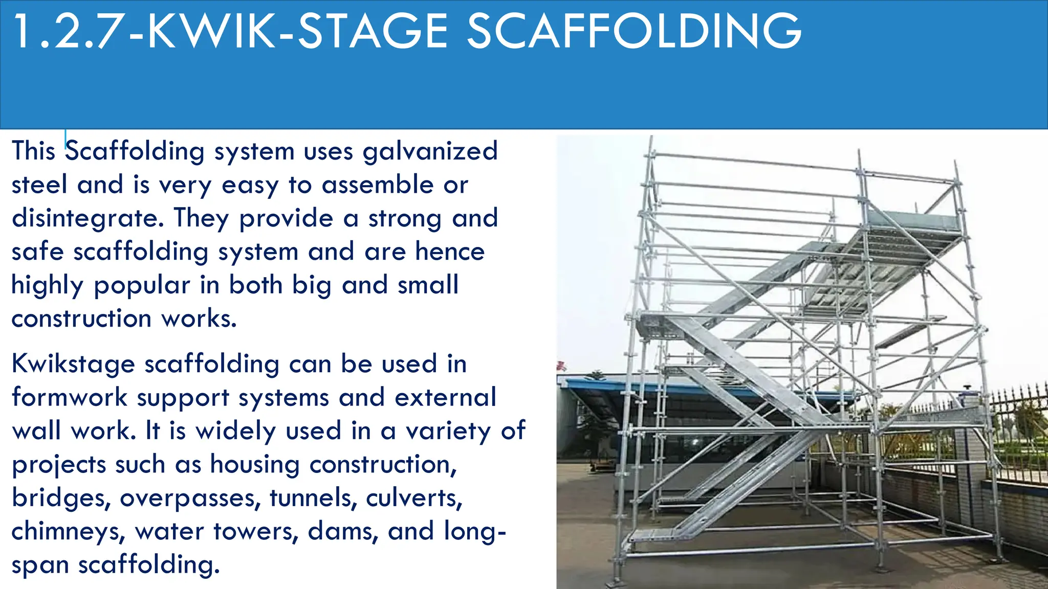
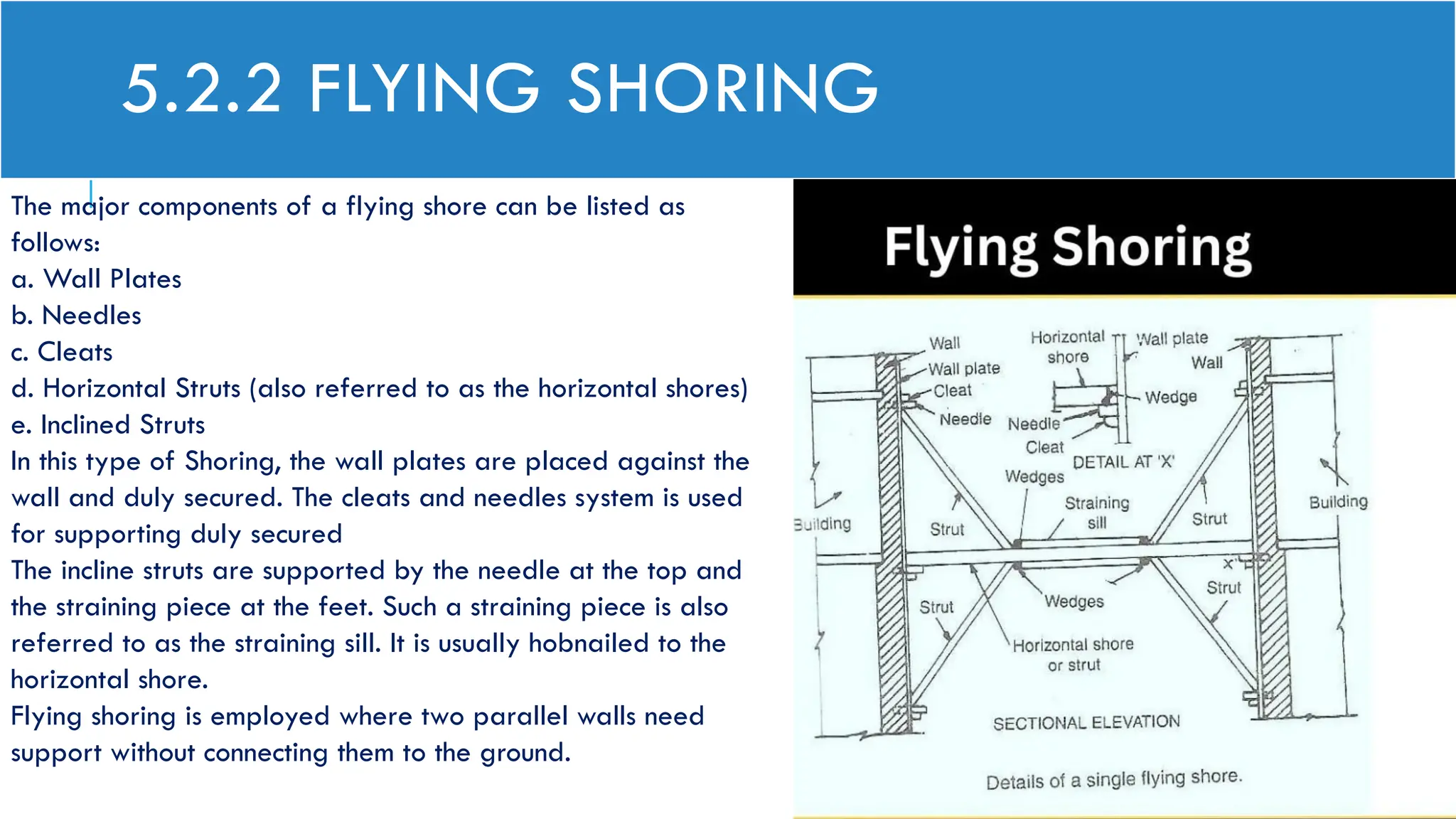
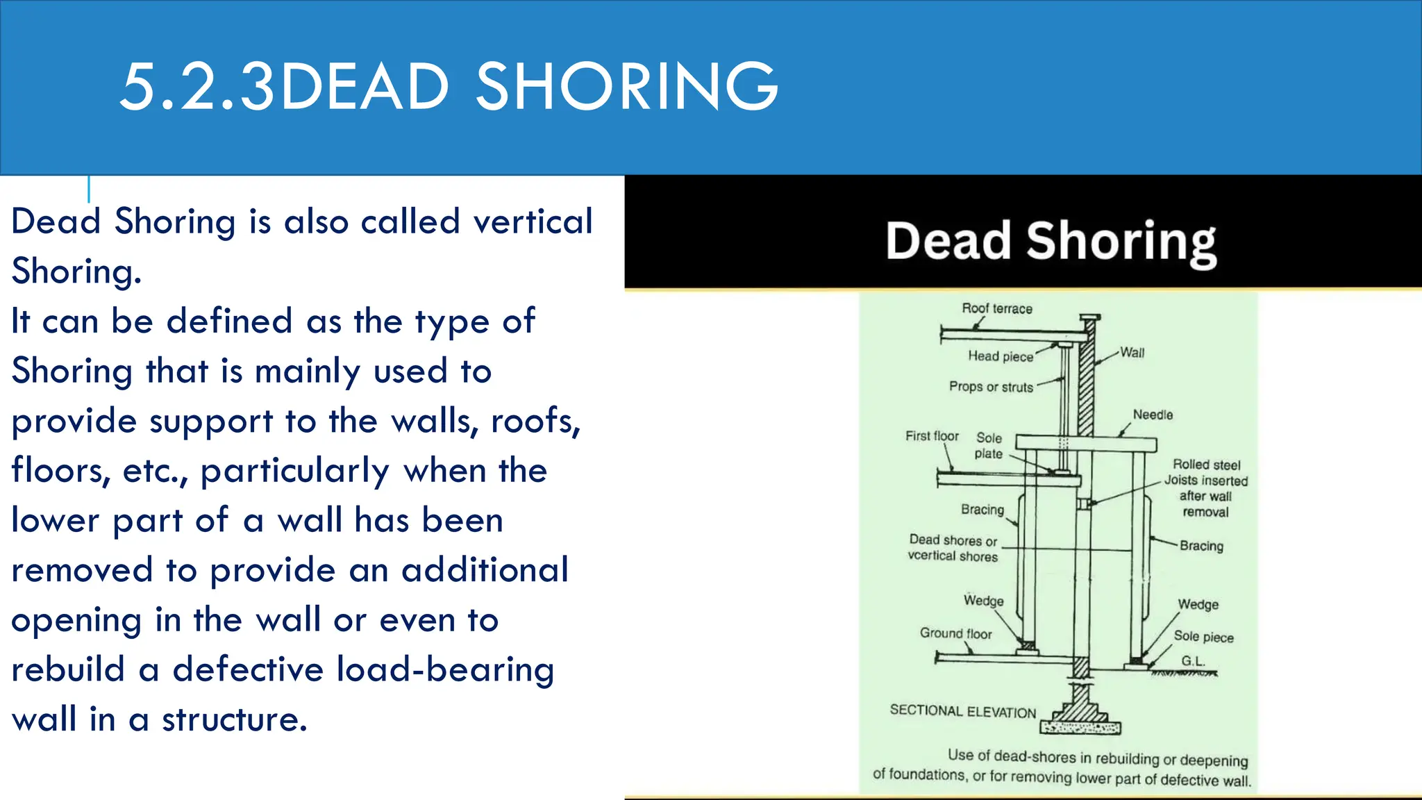
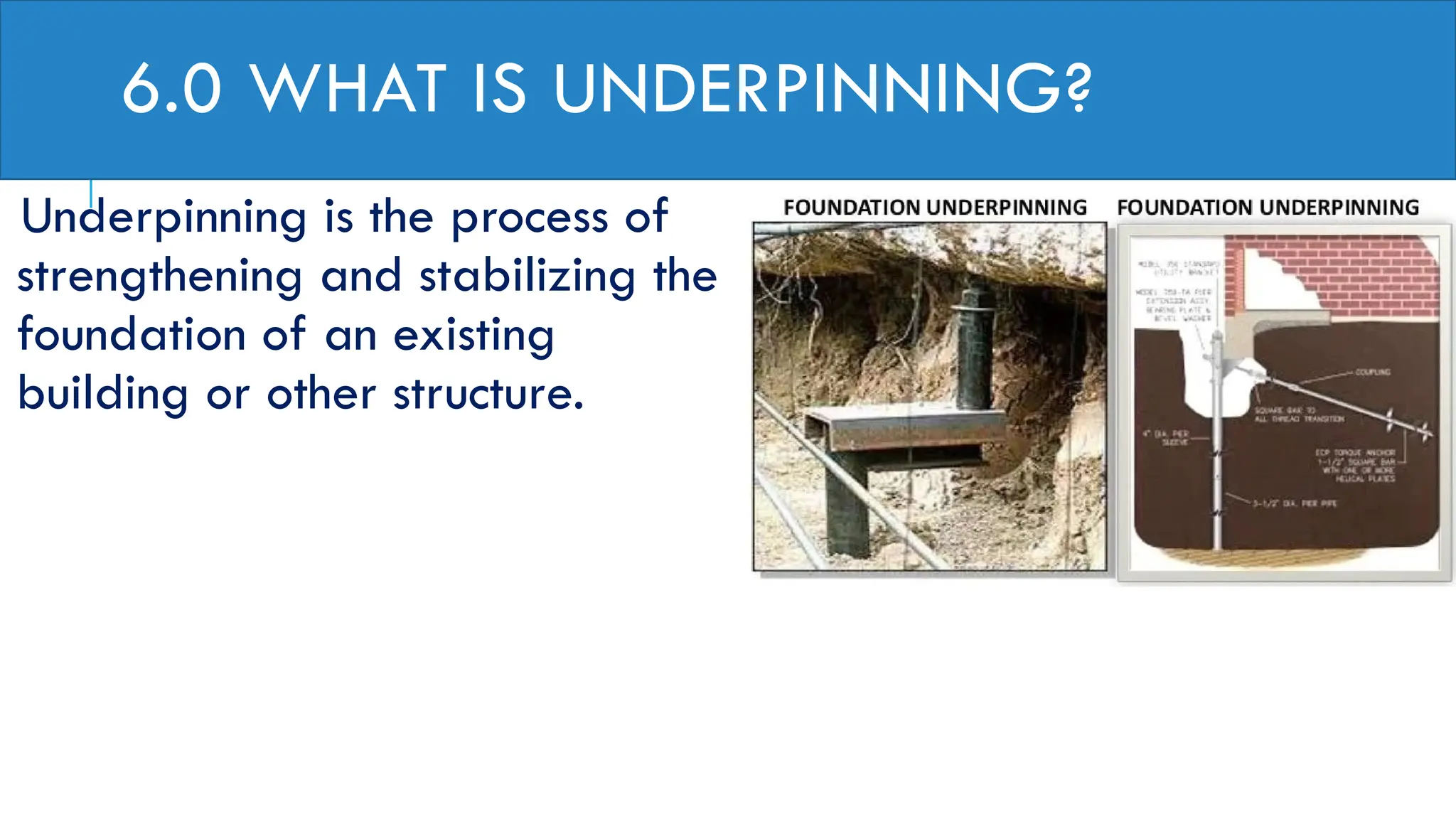
SCAFFOLDING, SHUTTERING AND
CENTERING BEAMS,
Lecture seris.11
Prepared by
Snr.Lctr.D.Mubarak Osman
1. SCAFFOLDING
1.1 Scaffolding Definition: Types, Parts, Design, Materials, and Hazards of
Scaffolding
Scaffolding Definition
During construction, maintenance, or repair work, to support the work crew and
materials, temporary structures are built. These temporary structures are called
Scaffolding. Scaffolding helps in access at heights and is widely used in all types of
construction works. This impermanent structure works as a platform to support the
working class to perform its construction activities. As scaffolding involves work at
height, it is designed following safety regulations to reduce hazards. Surveys show
that a major percentage of accidents in construction industries are directly or
indirectly related to scaffolding. So, the scaffolding contractor and scaffolding
workers should perform their duties with the utmost care. High-quality materials
should be used for scaffolding design.
1.1SCAFFOLDING PARTS OR COMPONENTS
The major components of scaffolding are as follows:
1. Standards: Perpendicular tubes that transfer the weight load to the baseplates. To increase the
height of scaffolding, standards are connected using pins and socket joints.
2. Ledgers: Flat horizontal tubes that join between the standards. Ledgers connect multiple bays.
Ledgers decide the height of the working platform.
3. Transom or Bearer: Transoms are used to support standards and they are at the right angles to
the ledgers. Transoms define the bay width
4. Scaffolding Tubes: Steel or Aluminum tubes are used in scaffolding.
5. Couplers: Fittings to hold tubes together. They are of three types; Putlog Coupler, Swivel
Couplers, and Right Angle Couplers.
6. Diagonal Braces: Strengthen the basic structure to carry more loads.
CONTINUE
7. Boards: Steel, Aluminum, or wooden boards that provide the working area.
8. Adjustable Base Plates
9. Guard Rails
10. Decks or planks
11.Toe Boards
12.Putlogs: Putlogs are transverse members that are placed on one end on ledgers
and the other ends at right angles on the wall
1.2 SCAFFOLDING TYPES
Depending on the type of construction and its requirements to meet various job
applications, the Scaffolding structure varies. Broadly, the following scaffolding types
are used in the construction industry:
1. Cantilever Scaffolding
2. Trestle Scaffolding
3. Single Scaffolding
4. Double Scaffolding
5. Steel Scaffolding
6. Suspended Scaffolding
7. Kwikstage Scaffolding
1.2.1- CANTILEVER SCAFFOLDING
Cantilever scaffolding is widely used where the
ground surface is not suitable for setting up
conventional scaffolding. Cantilever Scaffolding
or needle scaffolding is highly effective when
maintenance or construction is needed at great
heights or when the project has space
constraints. A group of cantilever or needle
beams is used to reinforce cantilever
scaffolding. Cantilever scaffolding is also known
as Single frame scaffolding.
A cantilever scaffolding normally constitutes of
the following components:
A Platform
Toe Boards
Protective rails
1.2.2-TRESTLE SCAFFOLDING
Trestle Scaffolding is a highly popular
movable scaffolding that can be used up to
a height of 5 m. They are fitted with wheels
and can be transferred from one place to
another very easily. They are used for light-
duty work, normally for indoor work.
1.2.3-SINGLE SCAFFOLDING
Single Scaffolding is made of only one
row. A series of vertical members are
fixed into the ground parallel to the
structure being made. Normally, a
single scaffolding is used for building
construction. This is also known as the
brick layer’s scaffolding.
1.2.4.DOUBLE SCAFFOLD
Double Scaffold, also known
as Mason's Scaffolding,
involves the use of two rows of
scaffolding for enhanced
stability. The first row is
parallel to the wall, while the
second row stands behind and
strengthens the first. It is
commonly used in stone or
brick masonry
1.2.5-STEEL SCAFFOLDING
Steel scaffolding is costly scaffolding
but provides greater strength and
durability and more resistance. In the
process and power piping industries,
steel scaffolding is widely used. As the
name denotes, the material used is
steel in steel scaffolding which can be
erected and dismantled quickly. Steel
scaffolding is suitable and safe for
working at great heights. For big
construction works steel scaffolding is
preferred over other types.
1.2.6-SUSPENDED SCAFFOLDING
As the name says, these
scaffoldings are suspended using
ropes or chains from overhead
structures. Mainly used for repair,
cleaning and painting works,
suspended scaffolding provides a
greater range of mobility as their
working height is adjustable
depending on height requirement.
1.2.7-KWIK-STAGE SCAFFOLDING
This Scaffolding system uses galvanized
steel and is very easy to assemble or
disintegrate. They provide a strong and
safe scaffolding system and are hence
highly popular in both big and small
construction works.
Kwikstage scaffolding can be used in
formwork support systems and external
wall work. It is widely used in a variety of
projects such as housing construction,
bridges, overpasses, tunnels, culverts,
chimneys, water towers, dams, and long-
span scaffolding.
1.3 SCAFFOLDING DESIGN
As Scaffolding involves the safety of working professionals it must be designed with utmost care. The
design of the scaffold should consider the following:
The supporting structure should be sufficient in strength, stability, and rigidity; The safety of
personnel associated with the erection, alteration, and dismantling of the scaffold; the safety of
persons using the scaffold; and the safety of persons in the vicinity of the scaffold
The following information is required for designing the scaffold:
The location of the Site.
Time Period for the scaffolding to be erected.
Intended use of the scaffolding.
Length and Height.
Maximum working loads.
Nature of surrounding supporting structure; etc.
CONTINUE
Scaffolding design should consider the worst load combination expected during its
service period. Dead (Weight of Structural members), Live loads (Weight of Persons),
and Occasional loads (wind, earthquake, snow, etc) are to be considered.
To avoid cracking the floor the beam deflection must be limited to 1/360(0.002)of
the span. Scaffolding where heavy loads are expected must be checked for this
deflection criteria.
1.4-SCAFFOLDING MATERIALS
The widely used materials for scaffolding are Steel and Aluminum.
Steel is the most preferred material for scaffolding due to its great strength and
durability. Also, Steel as Scaffolding material provides a certain amount of elasticity
to prevent cracks. Steel can support high loads, and workers can use it for
transporting heavy equipment and supplies. For tall scaffolding structures, steel
material is a necessity from the strength requirement point that only steel can
provide.
However, Aluminum is a good alternative for less demanding conditions with short
heights.
Scaffolding floors are normally made of wooden boards or decking made from
steel or aluminum. When wooden boards are used as scaffolding floor material,
their ends are protected by metal plates known as hoop irons or nail plates.
1.5-SCAFFOLDING HAZARDS AND RISKS
Working in scaffolding is full of risks. Scaffolding hazard increases with an increase in height.
Studies represent that more than 65% of the construction workforce needs to work on scaffolds.
Various incidents confirm the high frequency of scaffolding hazards. The major scaffolding hazards
are:
Falls from scaffolding due to improper guardrail installation.
The collapse of the scaffold due to improper erection.
Falling Material from scaffolds makes the nearby region vulnerable to hazards.
Electrical hazards due to improper planning.
Slips and falls from planks
Overloading platforms.
Rolling scaffolds.
CONTINUE
That’s why it is always suggested to inspect the scaffolding each day
before starting the construction work. Many organizations use a standard
checklist to ensure the scaffolding is suitable for working before work
begins. The Occupational Safety and Health Administration (OSHA)
provides guidelines for such checklists.
2-WHAT IS FORMWORK
Formwork is a temporary structure or a
mould to cast the concrete or other
material for getting the required shape
and size, assure strength, and facilitate
monolithic construction.
As the nature of concrete, fresh concrete
is in slurry form, which gets harden after
undergoing chemical change (hydration).
Hence to get the proper shape of
members like column, slab, and beam
formwork is required.
2.1 FORMWORK CAN BE DIVIDED INTO 2 PARTS,
CENTERING AND SHUTTERING.
The main components of the formwork include the column and main
bearer. The bearer is a horizontal member to bear the load from several
formwork bearers to pass off to the column.
The members of formwork which are used to support vertical and
horizontal member of the formwork are known as staging. Props, bullies
are examples of staging. Timber or steel tubes are generally used to
provide formworks.
Also, one should be clear on the fact that the components of the formwork
depend on either we are performing formwork for the wall or foundation,
or any other. The shape and orientation of sides depend upon how well
the formwork has been done.
2.2 REQUIREMENTS OF GOOD FORMWORK
The material used in the formwork should able to resist the pressure of
placing and compacting the concrete.
The joints should be well connected that, there is no leakage.
Formwork should be rigid enough to resist any deflection on the
member.
Members of the formwork are to be arranged purely mutually
perpendicular, to produce a structural component of approved size.
Formwork should be easily removable after the concrete gets harden,
therefore should be arranged in a sequence.
3.0 WHAT IS CENTERING AND SHUTTERING?
Centering is a horizontal Formwork whereas Shuttering is a vertical Formwork. For an
instance, in a building, formworks for columns, walls, and sides of the beam are
examples of shuttering and the bottom of the slabs and the beam are examples of
centering.
Centering and Shuttering is a crucial part of the construction. The slab floor should
be perfectly horizontal for the purpose to give a good working surface and to
transfer load uniformly.
The column should be perfectly vertical to avoid eccentric loading. Also, the inclined
member generates a moment that is not incurred in the designing phase.
3.1EQUIPMENT’S USED FOR CENTERING AND SHUTTERING
Ply Boards/Panels
Walers
Acrow Span
Clamps
CONTINUE
Battens
Adjustable Props with base plate
3.2 HOW IS CENTERING DONE?
Centering is done for slab and beam soffits. 3-layer thick waterproof ply
board is used in general. Before casting a mould , the strength of the
material and check for damages is performed.
The horizontal members should be of uniform thickness and properly
oiled.
Plates should be perfectly horizontal and at a right angle with the
vertical members.
Gaps between the plate are to be filled.
Staging is provided on the interval of about 600 mm center to center.
CONTINUE
The height of the staging is adjusted accordingly and bracing is to be
provided at 4 feet from the ground.
Staging should be rigid enough not to allow deflection.
The depth of the beam and slab to be cast are to be clearly marked.
Stripping time for the slab is at least 3 days and for the beam is 7 days
but the props(support) are to be removed only after 14 days for a span
of 4.5m.
Repairs are to be done if any damages occur, as soon as possible.
4.0 HOW IS SHUTTERING DONE?
There are certain things that need to be considered while performing shuttering
work. Before the work to be started, what kind of material to be used needs to be
checked, if any damages in the materials or found disfigured they should be
thoroughly repaired.
The inner side of the vertical members is oiled to ease the stripping process.
The members are clamps together with the help of walers or knot- bolt. Walers are
used in about 600 mm center to center distance.
The walers are used to avoid buckling while pouring the concrete and to resist the
pressure exerted on the shuttering members.
CONTINUE
Inclined members are also needed to make stand the member vertical.
In the case of columns, they should be aligned, which is generally checked by a stretching string.
The dimension and cover distance should not be compromised, and a plumb bob is used to check
the vertical alignment of the member.
The formwork should be rigid and leakage-free.
After 16-24 hours of placing concrete, stripping can be done if OPC(Ordinary Portland Cement) is
used.
The surface of the member along with its level line is checked.
If any damages, repairs should be made by consulting site supervisor.
If everything seems okay, the member is cured for at least 7 days.
4.1 DIFFERENCE BETWEEN CENTERING AND
SHUTTERING
Centering Shuttering
Centering is the horizontal component of the
formwork.
Shuttering are the vertical components of the
formwork.
Stripping time for centering, according to IS
code 456 is 3 days for slab and 7 days for
beam but the props are to be refaxed till 14
days for a span less than 4.5m and 21 days for
a span more than 6 m.
Stripping time for shuttering, according to the Is
code is 16-24 hours.
Centering is supported by vertical props. Shuttering are supported by inclined Props
5- Shoring And Underpinning In Building Construction
What is shoring?
Shoring is a general term used in
construction to describe the process of
supporting a structure in order to
prevent collapse so that construction
can proceed. The phrase can also be
used as a noun to refer to the materials
used in the process.
5.1USES OF SHORING IN BUILDING CONSTRUCTION
Shoring is used to support the beams and floors in a building while a column or wall is
removed. In this situation vertical supports are used as a temporary replacement for
the building columns or walls.
Trenches - During excavation, shoring systems provide safety for workers in a trench
and speed excavation. In this case, shoring should not be confused with shielding.
Shoring is designed to prevent collapse where shielding is only designed to protect
workers when collapses occur.
concrete structures shoring, in this case also referred to as false work, provides
temporary support until the concrete becomes hard and achieves the desired
strength to support loads.
5.2 SHORING TECHNIQUES IN BUILDING CONSTRUCTION
5.2.1 Raking Shore
Raking Shores consist of one or more timbers
sloping between the face of the structure to
be supported and the ground. The most
effective support is given if the raker meets
the wall at an angle of 60 to 70 degrees. A
wall-plate is typically used to increase the
area of support.
5.2.2 FLYING SHORING
The major components of a flying shore can be listed as
follows:
a. Wall Plates
b. Needles
c. Cleats
d. Horizontal Struts (also referred to as the horizontal shores)
e. Inclined Struts
In this type of Shoring, the wall plates are placed against the
wall and duly secured. The cleats and needles system is used
for supporting duly secured
The incline struts are supported by the needle at the top and
the straining piece at the feet. Such a straining piece is also
referred to as the straining sill. It is usually hobnailed to the
horizontal shore.
Flying shoring is employed where two parallel walls need
support without connecting them to the ground.
5.2.3DEAD SHORING
Dead Shoring is also called vertical
Shoring.
It can be defined as the type of
Shoring that is mainly used to
provide support to the walls, roofs,
floors, etc., particularly when the
lower part of a wall has been
removed to provide an additional
opening in the wall or even to
rebuild a defective load-bearing
wall in a structure.
6.0 WHAT IS UNDERPINNING?
Underpinning is the process of
strengthening and stabilizing the
foundation of an existing
building or other structure.
6.1 Underpinning May Be Necessary For A Variety Of Reasons:
The original foundation is simply not strong or stable enough, e.g. due to decay of
wooden piles under the foundation.
The usage of the structure has changed.
The properties of the soil supporting the foundation may have changed (possibly
through sinking) or were mischaracterized during planning.
The construction of nearby structures necessitates the excavation of soil supporting
existing foundations.
It is more economical, due to land price or otherwise, to work on the present
structure's foundation than to build a new one.
Underpinning is accomplished by extending the foundation in depth or in
breadth so it either rests on a stronger soil stratum or distributes its load
across a greater area. Use of micropiles and jet grouting are common
methods in underpinning. An alternative to underpinning is the
strengthening of the soil by the introduction of a grout. All of these
processes are generally expensive and elaborate.
Jet grouting is a ground improvement method used in construction to
increase strength and reduce permeability of soil. It involves drilling a
small-diameter hole to the required depth, and as the drill string is lifted
out of the ground, grout is injected into the borehole, forming a solid
column in the ground.

Scaffolding, Shuttering and centering beams

  • 1.
    SCAFFOLDING, SHUTTERING AND CENTERINGBEAMS, Lecture seris.11 Prepared by Snr.Lctr.D.Mubarak Osman
  • 2.
    1. SCAFFOLDING 1.1 ScaffoldingDefinition: Types, Parts, Design, Materials, and Hazards of Scaffolding Scaffolding Definition During construction, maintenance, or repair work, to support the work crew and materials, temporary structures are built. These temporary structures are called Scaffolding. Scaffolding helps in access at heights and is widely used in all types of construction works. This impermanent structure works as a platform to support the working class to perform its construction activities. As scaffolding involves work at height, it is designed following safety regulations to reduce hazards. Surveys show that a major percentage of accidents in construction industries are directly or indirectly related to scaffolding. So, the scaffolding contractor and scaffolding workers should perform their duties with the utmost care. High-quality materials should be used for scaffolding design.
  • 3.
    1.1SCAFFOLDING PARTS ORCOMPONENTS The major components of scaffolding are as follows: 1. Standards: Perpendicular tubes that transfer the weight load to the baseplates. To increase the height of scaffolding, standards are connected using pins and socket joints. 2. Ledgers: Flat horizontal tubes that join between the standards. Ledgers connect multiple bays. Ledgers decide the height of the working platform. 3. Transom or Bearer: Transoms are used to support standards and they are at the right angles to the ledgers. Transoms define the bay width 4. Scaffolding Tubes: Steel or Aluminum tubes are used in scaffolding. 5. Couplers: Fittings to hold tubes together. They are of three types; Putlog Coupler, Swivel Couplers, and Right Angle Couplers. 6. Diagonal Braces: Strengthen the basic structure to carry more loads.
  • 4.
    CONTINUE 7. Boards: Steel,Aluminum, or wooden boards that provide the working area. 8. Adjustable Base Plates 9. Guard Rails 10. Decks or planks 11.Toe Boards 12.Putlogs: Putlogs are transverse members that are placed on one end on ledgers and the other ends at right angles on the wall
  • 6.
    1.2 SCAFFOLDING TYPES Dependingon the type of construction and its requirements to meet various job applications, the Scaffolding structure varies. Broadly, the following scaffolding types are used in the construction industry: 1. Cantilever Scaffolding 2. Trestle Scaffolding 3. Single Scaffolding 4. Double Scaffolding 5. Steel Scaffolding 6. Suspended Scaffolding 7. Kwikstage Scaffolding
  • 7.
    1.2.1- CANTILEVER SCAFFOLDING Cantileverscaffolding is widely used where the ground surface is not suitable for setting up conventional scaffolding. Cantilever Scaffolding or needle scaffolding is highly effective when maintenance or construction is needed at great heights or when the project has space constraints. A group of cantilever or needle beams is used to reinforce cantilever scaffolding. Cantilever scaffolding is also known as Single frame scaffolding. A cantilever scaffolding normally constitutes of the following components: A Platform Toe Boards Protective rails
  • 8.
    1.2.2-TRESTLE SCAFFOLDING Trestle Scaffoldingis a highly popular movable scaffolding that can be used up to a height of 5 m. They are fitted with wheels and can be transferred from one place to another very easily. They are used for light- duty work, normally for indoor work.
  • 9.
    1.2.3-SINGLE SCAFFOLDING Single Scaffoldingis made of only one row. A series of vertical members are fixed into the ground parallel to the structure being made. Normally, a single scaffolding is used for building construction. This is also known as the brick layer’s scaffolding.
  • 10.
    1.2.4.DOUBLE SCAFFOLD Double Scaffold,also known as Mason's Scaffolding, involves the use of two rows of scaffolding for enhanced stability. The first row is parallel to the wall, while the second row stands behind and strengthens the first. It is commonly used in stone or brick masonry
  • 11.
    1.2.5-STEEL SCAFFOLDING Steel scaffoldingis costly scaffolding but provides greater strength and durability and more resistance. In the process and power piping industries, steel scaffolding is widely used. As the name denotes, the material used is steel in steel scaffolding which can be erected and dismantled quickly. Steel scaffolding is suitable and safe for working at great heights. For big construction works steel scaffolding is preferred over other types.
  • 12.
    1.2.6-SUSPENDED SCAFFOLDING As thename says, these scaffoldings are suspended using ropes or chains from overhead structures. Mainly used for repair, cleaning and painting works, suspended scaffolding provides a greater range of mobility as their working height is adjustable depending on height requirement.
  • 13.
    1.2.7-KWIK-STAGE SCAFFOLDING This Scaffoldingsystem uses galvanized steel and is very easy to assemble or disintegrate. They provide a strong and safe scaffolding system and are hence highly popular in both big and small construction works. Kwikstage scaffolding can be used in formwork support systems and external wall work. It is widely used in a variety of projects such as housing construction, bridges, overpasses, tunnels, culverts, chimneys, water towers, dams, and long- span scaffolding.
  • 14.
    1.3 SCAFFOLDING DESIGN AsScaffolding involves the safety of working professionals it must be designed with utmost care. The design of the scaffold should consider the following: The supporting structure should be sufficient in strength, stability, and rigidity; The safety of personnel associated with the erection, alteration, and dismantling of the scaffold; the safety of persons using the scaffold; and the safety of persons in the vicinity of the scaffold The following information is required for designing the scaffold: The location of the Site. Time Period for the scaffolding to be erected. Intended use of the scaffolding. Length and Height. Maximum working loads. Nature of surrounding supporting structure; etc.
  • 15.
    CONTINUE Scaffolding design shouldconsider the worst load combination expected during its service period. Dead (Weight of Structural members), Live loads (Weight of Persons), and Occasional loads (wind, earthquake, snow, etc) are to be considered. To avoid cracking the floor the beam deflection must be limited to 1/360(0.002)of the span. Scaffolding where heavy loads are expected must be checked for this deflection criteria.
  • 16.
    1.4-SCAFFOLDING MATERIALS The widelyused materials for scaffolding are Steel and Aluminum. Steel is the most preferred material for scaffolding due to its great strength and durability. Also, Steel as Scaffolding material provides a certain amount of elasticity to prevent cracks. Steel can support high loads, and workers can use it for transporting heavy equipment and supplies. For tall scaffolding structures, steel material is a necessity from the strength requirement point that only steel can provide. However, Aluminum is a good alternative for less demanding conditions with short heights. Scaffolding floors are normally made of wooden boards or decking made from steel or aluminum. When wooden boards are used as scaffolding floor material, their ends are protected by metal plates known as hoop irons or nail plates.
  • 17.
    1.5-SCAFFOLDING HAZARDS ANDRISKS Working in scaffolding is full of risks. Scaffolding hazard increases with an increase in height. Studies represent that more than 65% of the construction workforce needs to work on scaffolds. Various incidents confirm the high frequency of scaffolding hazards. The major scaffolding hazards are: Falls from scaffolding due to improper guardrail installation. The collapse of the scaffold due to improper erection. Falling Material from scaffolds makes the nearby region vulnerable to hazards. Electrical hazards due to improper planning. Slips and falls from planks Overloading platforms. Rolling scaffolds.
  • 18.
    CONTINUE That’s why itis always suggested to inspect the scaffolding each day before starting the construction work. Many organizations use a standard checklist to ensure the scaffolding is suitable for working before work begins. The Occupational Safety and Health Administration (OSHA) provides guidelines for such checklists.
  • 19.
    2-WHAT IS FORMWORK Formworkis a temporary structure or a mould to cast the concrete or other material for getting the required shape and size, assure strength, and facilitate monolithic construction. As the nature of concrete, fresh concrete is in slurry form, which gets harden after undergoing chemical change (hydration). Hence to get the proper shape of members like column, slab, and beam formwork is required.
  • 20.
    2.1 FORMWORK CANBE DIVIDED INTO 2 PARTS, CENTERING AND SHUTTERING. The main components of the formwork include the column and main bearer. The bearer is a horizontal member to bear the load from several formwork bearers to pass off to the column. The members of formwork which are used to support vertical and horizontal member of the formwork are known as staging. Props, bullies are examples of staging. Timber or steel tubes are generally used to provide formworks. Also, one should be clear on the fact that the components of the formwork depend on either we are performing formwork for the wall or foundation, or any other. The shape and orientation of sides depend upon how well the formwork has been done.
  • 21.
    2.2 REQUIREMENTS OFGOOD FORMWORK The material used in the formwork should able to resist the pressure of placing and compacting the concrete. The joints should be well connected that, there is no leakage. Formwork should be rigid enough to resist any deflection on the member. Members of the formwork are to be arranged purely mutually perpendicular, to produce a structural component of approved size. Formwork should be easily removable after the concrete gets harden, therefore should be arranged in a sequence.
  • 22.
    3.0 WHAT ISCENTERING AND SHUTTERING? Centering is a horizontal Formwork whereas Shuttering is a vertical Formwork. For an instance, in a building, formworks for columns, walls, and sides of the beam are examples of shuttering and the bottom of the slabs and the beam are examples of centering. Centering and Shuttering is a crucial part of the construction. The slab floor should be perfectly horizontal for the purpose to give a good working surface and to transfer load uniformly. The column should be perfectly vertical to avoid eccentric loading. Also, the inclined member generates a moment that is not incurred in the designing phase.
  • 23.
    3.1EQUIPMENT’S USED FORCENTERING AND SHUTTERING Ply Boards/Panels Walers Acrow Span Clamps
  • 24.
  • 25.
    3.2 HOW ISCENTERING DONE? Centering is done for slab and beam soffits. 3-layer thick waterproof ply board is used in general. Before casting a mould , the strength of the material and check for damages is performed. The horizontal members should be of uniform thickness and properly oiled. Plates should be perfectly horizontal and at a right angle with the vertical members. Gaps between the plate are to be filled. Staging is provided on the interval of about 600 mm center to center.
  • 26.
    CONTINUE The height ofthe staging is adjusted accordingly and bracing is to be provided at 4 feet from the ground. Staging should be rigid enough not to allow deflection. The depth of the beam and slab to be cast are to be clearly marked. Stripping time for the slab is at least 3 days and for the beam is 7 days but the props(support) are to be removed only after 14 days for a span of 4.5m. Repairs are to be done if any damages occur, as soon as possible.
  • 27.
    4.0 HOW ISSHUTTERING DONE? There are certain things that need to be considered while performing shuttering work. Before the work to be started, what kind of material to be used needs to be checked, if any damages in the materials or found disfigured they should be thoroughly repaired. The inner side of the vertical members is oiled to ease the stripping process. The members are clamps together with the help of walers or knot- bolt. Walers are used in about 600 mm center to center distance. The walers are used to avoid buckling while pouring the concrete and to resist the pressure exerted on the shuttering members.
  • 28.
    CONTINUE Inclined members arealso needed to make stand the member vertical. In the case of columns, they should be aligned, which is generally checked by a stretching string. The dimension and cover distance should not be compromised, and a plumb bob is used to check the vertical alignment of the member. The formwork should be rigid and leakage-free. After 16-24 hours of placing concrete, stripping can be done if OPC(Ordinary Portland Cement) is used. The surface of the member along with its level line is checked. If any damages, repairs should be made by consulting site supervisor. If everything seems okay, the member is cured for at least 7 days.
  • 29.
    4.1 DIFFERENCE BETWEENCENTERING AND SHUTTERING Centering Shuttering Centering is the horizontal component of the formwork. Shuttering are the vertical components of the formwork. Stripping time for centering, according to IS code 456 is 3 days for slab and 7 days for beam but the props are to be refaxed till 14 days for a span less than 4.5m and 21 days for a span more than 6 m. Stripping time for shuttering, according to the Is code is 16-24 hours. Centering is supported by vertical props. Shuttering are supported by inclined Props
  • 30.
    5- Shoring AndUnderpinning In Building Construction What is shoring? Shoring is a general term used in construction to describe the process of supporting a structure in order to prevent collapse so that construction can proceed. The phrase can also be used as a noun to refer to the materials used in the process.
  • 31.
    5.1USES OF SHORINGIN BUILDING CONSTRUCTION Shoring is used to support the beams and floors in a building while a column or wall is removed. In this situation vertical supports are used as a temporary replacement for the building columns or walls. Trenches - During excavation, shoring systems provide safety for workers in a trench and speed excavation. In this case, shoring should not be confused with shielding. Shoring is designed to prevent collapse where shielding is only designed to protect workers when collapses occur. concrete structures shoring, in this case also referred to as false work, provides temporary support until the concrete becomes hard and achieves the desired strength to support loads.
  • 32.
    5.2 SHORING TECHNIQUESIN BUILDING CONSTRUCTION 5.2.1 Raking Shore Raking Shores consist of one or more timbers sloping between the face of the structure to be supported and the ground. The most effective support is given if the raker meets the wall at an angle of 60 to 70 degrees. A wall-plate is typically used to increase the area of support.
  • 33.
    5.2.2 FLYING SHORING Themajor components of a flying shore can be listed as follows: a. Wall Plates b. Needles c. Cleats d. Horizontal Struts (also referred to as the horizontal shores) e. Inclined Struts In this type of Shoring, the wall plates are placed against the wall and duly secured. The cleats and needles system is used for supporting duly secured The incline struts are supported by the needle at the top and the straining piece at the feet. Such a straining piece is also referred to as the straining sill. It is usually hobnailed to the horizontal shore. Flying shoring is employed where two parallel walls need support without connecting them to the ground.
  • 34.
    5.2.3DEAD SHORING Dead Shoringis also called vertical Shoring. It can be defined as the type of Shoring that is mainly used to provide support to the walls, roofs, floors, etc., particularly when the lower part of a wall has been removed to provide an additional opening in the wall or even to rebuild a defective load-bearing wall in a structure.
  • 35.
    6.0 WHAT ISUNDERPINNING? Underpinning is the process of strengthening and stabilizing the foundation of an existing building or other structure.
  • 36.
    6.1 Underpinning MayBe Necessary For A Variety Of Reasons: The original foundation is simply not strong or stable enough, e.g. due to decay of wooden piles under the foundation. The usage of the structure has changed. The properties of the soil supporting the foundation may have changed (possibly through sinking) or were mischaracterized during planning. The construction of nearby structures necessitates the excavation of soil supporting existing foundations. It is more economical, due to land price or otherwise, to work on the present structure's foundation than to build a new one.
  • 37.
    Underpinning is accomplishedby extending the foundation in depth or in breadth so it either rests on a stronger soil stratum or distributes its load across a greater area. Use of micropiles and jet grouting are common methods in underpinning. An alternative to underpinning is the strengthening of the soil by the introduction of a grout. All of these processes are generally expensive and elaborate. Jet grouting is a ground improvement method used in construction to increase strength and reduce permeability of soil. It involves drilling a small-diameter hole to the required depth, and as the drill string is lifted out of the ground, grout is injected into the borehole, forming a solid column in the ground.