Zenergy Power has been developing an inductive-type of
fault current limiter (FCL) for electric power grid
applications. In March 2009 Zenergy Power installed a
FCL in the Avanti distribution circuit of Southern
California Edison’s Shandin substation in San Bernardino,
CA, rated at 15 kV and 1,200 amperes steady-state. In
January 2010, this device successfully limited its first series
of real-world faults when the circuit experienced multiple
single-phase and three-phase faults. Zenergy Power also
received contracts to deliver an 11 kV, 1,250 amperes FCL
for the CE Electric UK grid and a 138 kV, 1,300 amperes
FCL for the Tidd substation of American Electric Power.
Design, Test and Demonstration of Saturable Reactor High-Temperature Supercon...Franco Moriconi
Zenergy Power has successfully designed, built, tested, and installed in the US electrical grid a saturable reactor Fault Current Limiter. Beginning in 2007, first as SC Power Systems and from 2008 as Zenergy Power, Inc., ZP used DOE matching grant and ARRA funds to help refine the design of the saturated reactor fault current limiter.
This paper presents 230 66 kV, substation grounding system and calculation results of required parameters. The grounding system is essential to protect people working or walking in the vicinity of earthed facilities and equipments against the danger of electric shock. This paper provides the floor surface either assures an effective insulation from earth potential or effectively equipment to a close mesh grid. Calculations of grounding grid system in the substation area which the top soil layer resistivity is less than the bottom layer resistivity, can lessen the number of ground rod used in the grid because the value of Ground Potential Rise GPR is insignificantly different. Essential equations are used in the design of grounding system to get desired parameters such as touch and step voltage criteria for safety, earth resistance, grid resistance, maximum grid current, minimum conductor size and electrode size, maximum fault current level and resistivity of soil. Calculations of three separate earthing body earth, neutral earth and main earthing are described. Zin Wah Aung | Aung Thike "Design of Grounding System for Substation" Published in International Journal of Trend in Scientific Research and Development (ijtsrd), ISSN: 2456-6470, Volume-3 | Issue-5 , August 2019, URL: https://www.ijtsrd.com/papers/ijtsrd26641.pdfPaper URL: https://www.ijtsrd.com/engineering/electrical-engineering/26641/design-of-grounding-system-for-substation/zin-wah-aung
Types of islands in power systems with DR
Issues with unintentional islands
Methods of protecting against unintentional islands
Standard testing for unintentional islanding
Advanced testing of inverters for anti-islanding functionality
Probability of unintentional islanding
The future of anti-islanding protection
Center for Superconducting and Magnetic Materials (CSMM), Research and Facili...The Ohio State University
Summary of the present (5/09) state of the research and facilities in the Center for Superconducting and Magnetic Materials (CSMM). Department of Materials Science and Engineering, The Ohio State University
Quasi-z-source inverter for photovoltaic power generation systemsijiert bestjournal
The Z-Source Inverter (ZSI) has been reported suitable for res idential PV system because of the capability of voltage boost and inversion in a single stage. Recently,four new topol ogies,the quasi-Z-Source Inverters (qZSI),have been derived from the original ZSI. This project ana lyzes one voltage fed topology of these four in detail and applies it to PV power generation systems. By using the new quasi-Z-Source topology,the inverter draws a constant current from the PV array and is capabl e of handling a wide input voltage range. It also features lower component ratings and reduced source stress compared to the traditional ZSI. A prototype which provides three phase 50-Hz,230Vrms ac has been built in laboratory . It is demonstrated from the theoretical analysis and MATLAB/SIMULATION results that t he proposed qZSI can realize voltage buck or boost and dc-ac inversion in a single stage with high reliability and efficiency,which makes it well suited for PV power systems.
Wireless power transmission project is used to transfer the power from the power source to electrical loads using high frequency resonating air core transformers.
In offshore oil & gas installation, the electrical power system consists of a large distribution
network, generally operating in island mode i.e., without grid support.
International Refereed Journal of Engineering and Science (IRJES) is a peer reviewed online journal for professionals and researchers in the field of computer science. The main aim is to resolve emerging and outstanding problems revealed by recent social and technological change. IJRES provides the platform for the researchers to present and evaluate their work from both theoretical and technical aspects and to share their views.
www.irjes.com
IjEVOLUTION OF POWER SUPPLY AND ITS APPLICATION TO ELECTRICAL AND ELECTRONIC ...IAEME Publication
Electricity can be produced using chemical effect where the movement of ions constitutes a flow of current through the electrolyte. Electrochemical cells are used as storage cells where chemical energy can be converted into electrical energy. The most efficient and widely used method for the generation of electricity is based on the laws of Electromagnetic Induction. According to this law electromotive force is induced in a conductor whenever the conductor cuts across magnetic lines of flux. The invention of the Diode Valve in 1904 and the invention of the triode valve in 1906 and their largescale production from 1920 onwards helped to manufacture electronic products and instruments. The invention of the galena-based Cat’s whisker detector in 1906 was the milestone of manufacturing crystal radio receivers. Cuprous oxide rectifier was invented in 1926 and was used for the rectification of power supply frequencies. Selenium rectifier was invented in 1933 and it was also used for the rectification of power frequencies but selenium rectifier was more efficient and was best in low-voltage, heavy current applications. Commercial manufacturing of germanium crystal diode was started in 1946. Then invention of the bipolar junction transistor in 1948 had replaced the valves because of low power, low cost, small size and long-lasting. Electrical products are generally operated from the mains power supply. But electronic products are operated by D.C supply and nowadays most of the communication devices are designed to be operated by the low-watt power supply. Scientists and researchers are developing low power, low heat dissipation, low dropout, miniature and energy harvesting efficient power supply.
This Document Contains Abstract, Block Diagrams, Cuircuit Diagrams, Explanation, Working Etc. This is a project our group made for 1st Sem Engineering.
This ppt explains Metal Detector Robotic Vehicle, student is provided with his/her authorized tag to swipe over the reader to record their attendance.
Edgefxkits.com has a wide range of electronic projects ideas that are primarily helpful for ECE, EEE and EIE students and the ideas can be applied for real life purposes as well.
http://www.edgefxkits.com/
Visit our page to get more ideas on popular electronic projects developed by professionals.
Edgefx provides free verified electronic projects kits around the world with abstracts, circuit diagrams, and free electronic software. We provide guidance manual for Do It Yourself Kits (DIY) with the modules at best price along with free shipping.
This handy, it can be used to prevent use of mobile phones in examination halls, confidential rooms and, etc. It is also useful for detecting the use of mobile phone for Spying and unauthorized video transmission. The circuit can detect the incoming calls pocket-size mobile transmission detector or sniffer can sense the presence of an activated mobile cell phone from a distance of one and-a-half meters. So and also outgoing calls, SMS and video transmissions even if the mobile phone is kept in the silent mode. The moment the Bug detects RF transmission signal from an activated mobile phone, it starts sounding a beep alarm and the LED blinks. The alarm continues until the signal transmission ceases. The capacitor C3 should have a lead length of 18 mm with lead spacing of 8 mm. we have to carefully solder the capacitor in standing position with equal spacing of the leads. The response can be optimized by trimming the lead length of C3 for the desired frequency. We are using a short telescopic type antenna. The unit will give the warning indication if someone uses Mobile phone within a radius of 1.5 meters.
Development and Deployment of Saturated-Core Fault Current Limiters in Distri...Franco Moriconi
Zenergy Power has been developing an inductive-type of fault current limiter (FCL) for electric power grid applications. The FCL employs a magnetically saturating reactor concept which acts as a variable inductor in an electric circuit. In March 2009 Zenergy Power, with funding from the California Energy Commission and the U.S. Department of Energy (DOE), installed an FCL in the Avanti distribution circuit of Southern California Edison’s Shandin substation in San Bernardino, CA. Rated at 15 kV and 1,250 amperes steady-state, the “Avanti” device is the first superconductor FCL installed in a US utility. In January 2010, the “Avanti” device successfully limited its first series of real-world faults when the circuit experienced multiple single-phase and three-phase faults. After successfully validating the performance of a new “compact” saturated-core FCL, Zenergy Power received contracts to install a 12 kV, 1,250 amperes compact FCL in the CE Electric UK grid in early 2011 and a 138 kV, 1,300 amperes FCL at the Tidd substation of American Electric Power in late 2011.
Single core configurations of saturated core fault current limiter performanc...IJECEIAES
Economic growth with industrialization and urbanization lead to an extensive increase in power demand. It forced the utilities to add power generating facilities to cause the necessary demand-generation balance. The bulk power generating stations, mostly interconnected, with the penetration of distributed generation result in an enormous rise in the fault level of power networks. It necessitates for electrical utilities to control the fault current so that the existing switchgear can continue its services without upgradation or replacement for reliable supply. The deployment of fault current limiter (FCL) at the distribution and transmission networks has been under investigation as a potential solution to the problem. A saturated core fault current limiter (SCFCL) technology is a smart, scalable, efficient, reliable, and commercially viable option to manage fault levels in existing and future MV/HV supply systems. This paper presents the comparative performance analysis of two single-core SCFCL topologies impressed with different core saturations. It has demonstrated that the single AC winding configuration needs more bias power for affecting the same current limiting performance with an acceptable steady-state voltage drop contribution. The fault state impedance has a transient nature, and the optimum bias selection is a critical design parameter in realizing the SCFCL applications.
Modeling and test validation of a 15 kV - 24 MVA superconducting fault curren...Franco Moriconi
High-power short-circuit test results and numerical simulations of a 15kV–24MVA distribution-class High Temperature Superconductor (HTS) Fault Current Limiters (FCL) are presented and compared in this paper. The FCL design was based on the nonlinear inductance model here described, and the device was tested at 13.1kV line-to-line voltage for prospective fault currents up to 23kArms, prior to its installation in the electric grid. Comparison between numerical simulations and fault test measurements show good agreement. Some simulations and field testing results are depicted. The FCL was energized in the Southern California Edison grid on March 9, 2009.
Darfield to Dunsandel and Beyond - The Development of the Ground Fault Neutra...Dennis Keen
This paper develops from the Papers presented at the EEA Conferences in 2006 by Stephen Hirsch – “Resonant Earthing - Advantages & Disadvantages. Why do we not use it in New Zealand?” which posed the question and discussed why we should use Neutral Earthing in New Zealand and goes onto briefly mention the first Ground Fault Neutralizer system installed at Darfield by Orion, presented at the EEA conference in 2007. By Tas Scott. – “The First Application of Resonant Earthing with Residual Current Compensation to a NZ Distribution Network” The paper considers the developments and learning’s that Orion have had since then with further installations at their own network substations and at other Network companies in New Zealand and Australia.
TCSC AND SVC OPTIMAL LOCATION TO IMPROVE THE PERFORMANCE OF POWER SYSTEM WITH...eeiej_journal
Wind generation connection to power system affects steady state and transient stability. Furthermore, this
effect increases with the increase of wind penetration in generation capacity. In this paper optimal location
of FACTS devices is carried out to solve the steady state problems of wind penetration. Two case studies
are carried out on modified IEEE39 bus system one with wind reduction to 20% and the second with wind
penetration increase by 50% in the two cases system suffer from outage of one generator with load at bus
39 decreases from 1104 MW to 900 MW.
Transient Recovery Voltage Test Results of a 25 MVA Saturable-Core Fault Curr...Franco Moriconi
Test results obtained during fault current interruption tests with an air-core reactor are compared to test results obtained using a saturating-core inductive HTS Fault Current Limiter in the same circuit under the same circumstances. These test results are further compared with analytical simulations developed using the PSCAD® software suite. The simulations exhibit good agreement with the test results and confirm that compared to an equivalent air-core reactor, the HTS FCL results in lower amplitude and significantly lower rate of rise of the Transient Recovery Voltage.
Harmonic Mitigation in Distribution System by using Passive Filtersijtsrd
The advent of power electronics and computerized equipment in recent decades has brought enhanced efficiency and improved system but at the same time also created harmonics and waveform distortion to the power system network. Due to the growing use of nonlinear load equipment and new technologies in buildings, harmonic currents and voltages generated in distribution systems pose a new problem for electrical engineers. This is a serious problem when power quality is a prime concern. Harmonics are the main types of power quality problem that are very common to the power system containing electric arc furnace EAF . Electric arc furnace EAFs are widely used in steelmaking and in melting of nonferrous metals. In this paper, EAF is presented guide lines for the accurate evaluation of harmonics generated in No. 3 Steel Mill, Ywama, Yangon. Passive filters have been most commonly used to limit the flow of harmonic currents in distribution systems. Their performance is limited to a few harmonics, and they can introduce resonance in the power system. Nyein Nyein Chan | Hnin Wai Hlaing "Harmonic Mitigation in Distribution System by using Passive Filters" Published in International Journal of Trend in Scientific Research and Development (ijtsrd), ISSN: 2456-6470, Volume-3 | Issue-1 , December 2018, URL: http://www.ijtsrd.com/papers/ijtsrd19027.pdf
http://www.ijtsrd.com/engineering/electrical-engineering/19027/harmonic-mitigation-in-distribution-system-by-using-passive-filters/nyein-nyein-chan
Modeling and control of HVDC grids: a key challenge for the future power systemPower System Operation
HVDC technology is developing fast and HVDC
grids are increasingly seen as a possible and feasible solution
to manage the future power system with large amounts of
renewables in a secure and cost-effective manner. However,
systems with significant amounts of DC transmission behave
in a fundamentally different manner when compared to the
traditional AC power system. The integration of HVDC systems
introduces new fast dynamics on different time frames and adds
controllability to the combined system. As a result, the modeling
and control of the entire interconnected system needs to be reevaluated
in order to accurately compute the system behavior,
both from the AC and DC system.
This survey paper gives an overview of the current research
in the field of HVDC grids focusing on the interaction of the AC
and DC system. The converters and their behavior are discussed
in greater detail. A second component which is discussed is the
DC breaker. Both devices operate fundamentally different than
their AC counterparts. The fast interaction between AC and DC
systems requires changes in the manner in which the modeling
and computation of the system is done, both at the DC and
the AC side. Although these considerations are needed within all
relevant time frames, two relevant cases are specifically addressed
in this paper: the connection of offshore wind power through a
HVDC system and the optimal operation of the power system
with a strong presence of HVDC.
APPENDICES California Energy Commission 500-2013-134-APPENDIXESFranco Moriconi
APPENDIX A: Zenergy Power HTS FCL Test Plan APPENDIX B: Zenergy Power HTS FCL Laboratory Test APPENDIX C: Zenergy Power HTS FCL Dielectric and HV Tests
APPENDIX D: Zenergy Power HTS FCL Normal State Temperature Rise Test
APPENDIX E: Zenergy Power HTS FCL Short Circuit Test APPENDIX F: Zenergy Power HTS FCL High Voltage Field Test
APPENDIX G: Zenergy Power HTS FCL Operation Manual APPENDIX H: Zenergy Power HTS FCL Cryostat Evacuation and Moisture Removal Procedure
APPENDIX I: Zenergy Power HTS FCL Liquid Nitrogen Fill Procedure
An innovative compact saturable-core HTS Fault Current Limiter - development,...Franco Moriconi
The development and testing of an innovative and compact saturating-reactor High Temperature Superconductor Fault Current Limiter (HTS FCL) is described. The development includes an initial dry-type magnetic core design with iron cores partially encircled by an HTS DC coil and a recently completed oil-immersed design with magnetic cores enclosed in a metallic tank placed inside the warm bore of a rectangular HTS DC magnet. The first 15 kV HTS FCL was installed in Southern California Edison’s grid in 2009 and the first transmission-class 138 kV Compact HTS FCL is planned to be in operation in American Electric Power’s grid in 2011.
Resonance of a distribution feeder with a saturable core fault current limiterFranco Moriconi
Simulations of a resonance event were performed based on actual field data of a commercially operating distribution feeder and a superconducting saturable core fault current limiter. The analysis was conducted from both the system's and the fault current limiter's perspectives. Agreement in the results of the two approaches showed that under certain values of reactive shunt compensation, full insertion of the limiter's reactance, and low load conditions, a sustained but damped resonance can occur. Resonance suppression preventive measures for these conditions are proposed.
Inductive shielded superconducting fault current limiter: test results for sc...Franco Moriconi
Results of measurements with a downscaled model of a novel superconducting inductive Shielded Fault Current Limiter (iSFCL) based on 2nd generation HTS material are reported. Two different types of models were tested, one with an open iron core and one with a closed iron core. The operational characteristics of both systems with focus on the superconducting secondary modules in normal operation and in quenching mode with quench times of up to 500 ms are analyzed. The HTS modules are based on 40 mm wide YBCO coated conductors with a high-ohmic protection layer and an external shunt system. Further development/testing program includes a 3-phase-field trial, where a full scale technology demonstrator (15-MVA class) will be integrated in the distribution grid of the utility Stadtwerke Augsburg in Germany. This joint project of Schneider Electric, Bruker HTS, Bruker Advanced Supercon and Stadtwerke Augsburg is supported by the German Federal Ministry of Economics and Technology (BMWi)
Buy Verified PayPal Account | Buy Google 5 Star Reviewsusawebmarket
Buy Verified PayPal Account
Looking to buy verified PayPal accounts? Discover 7 expert tips for safely purchasing a verified PayPal account in 2024. Ensure security and reliability for your transactions.
PayPal Services Features-
🟢 Email Access
🟢 Bank Added
🟢 Card Verified
🟢 Full SSN Provided
🟢 Phone Number Access
🟢 Driving License Copy
🟢 Fasted Delivery
Client Satisfaction is Our First priority. Our services is very appropriate to buy. We assume that the first-rate way to purchase our offerings is to order on the website. If you have any worry in our cooperation usually You can order us on Skype or Telegram.
24/7 Hours Reply/Please Contact
usawebmarketEmail: support@usawebmarket.com
Skype: usawebmarket
Telegram: @usawebmarket
WhatsApp: +1(218) 203-5951
USA WEB MARKET is the Best Verified PayPal, Payoneer, Cash App, Skrill, Neteller, Stripe Account and SEO, SMM Service provider.100%Satisfection granted.100% replacement Granted.
Company Valuation webinar series - Tuesday, 4 June 2024FelixPerez547899
This session provided an update as to the latest valuation data in the UK and then delved into a discussion on the upcoming election and the impacts on valuation. We finished, as always with a Q&A
Digital Transformation and IT Strategy Toolkit and TemplatesAurelien Domont, MBA
This Digital Transformation and IT Strategy Toolkit was created by ex-McKinsey, Deloitte and BCG Management Consultants, after more than 5,000 hours of work. It is considered the world's best & most comprehensive Digital Transformation and IT Strategy Toolkit. It includes all the Frameworks, Best Practices & Templates required to successfully undertake the Digital Transformation of your organization and define a robust IT Strategy.
Editable Toolkit to help you reuse our content: 700 Powerpoint slides | 35 Excel sheets | 84 minutes of Video training
This PowerPoint presentation is only a small preview of our Toolkits. For more details, visit www.domontconsulting.com
Cracking the Workplace Discipline Code Main.pptxWorkforce Group
Cultivating and maintaining discipline within teams is a critical differentiator for successful organisations.
Forward-thinking leaders and business managers understand the impact that discipline has on organisational success. A disciplined workforce operates with clarity, focus, and a shared understanding of expectations, ultimately driving better results, optimising productivity, and facilitating seamless collaboration.
Although discipline is not a one-size-fits-all approach, it can help create a work environment that encourages personal growth and accountability rather than solely relying on punitive measures.
In this deck, you will learn the significance of workplace discipline for organisational success. You’ll also learn
• Four (4) workplace discipline methods you should consider
• The best and most practical approach to implementing workplace discipline.
• Three (3) key tips to maintain a disciplined workplace.
The world of search engine optimization (SEO) is buzzing with discussions after Google confirmed that around 2,500 leaked internal documents related to its Search feature are indeed authentic. The revelation has sparked significant concerns within the SEO community. The leaked documents were initially reported by SEO experts Rand Fishkin and Mike King, igniting widespread analysis and discourse. For More Info:- https://news.arihantwebtech.com/search-disrupted-googles-leaked-documents-rock-the-seo-world/
Affordable Stationery Printing Services in Jaipur | Navpack n PrintNavpack & Print
Looking for professional printing services in Jaipur? Navpack n Print offers high-quality and affordable stationery printing for all your business needs. Stand out with custom stationery designs and fast turnaround times. Contact us today for a quote!
Personal Brand Statement:
As an Army veteran dedicated to lifelong learning, I bring a disciplined, strategic mindset to my pursuits. I am constantly expanding my knowledge to innovate and lead effectively. My journey is driven by a commitment to excellence, and to make a meaningful impact in the world.
Putting the SPARK into Virtual Training.pptxCynthia Clay
This 60-minute webinar, sponsored by Adobe, was delivered for the Training Mag Network. It explored the five elements of SPARK: Storytelling, Purpose, Action, Relationships, and Kudos. Knowing how to tell a well-structured story is key to building long-term memory. Stating a clear purpose that doesn't take away from the discovery learning process is critical. Ensuring that people move from theory to practical application is imperative. Creating strong social learning is the key to commitment and engagement. Validating and affirming participants' comments is the way to create a positive learning environment.
[Note: This is a partial preview. To download this presentation, visit:
https://www.oeconsulting.com.sg/training-presentations]
Sustainability has become an increasingly critical topic as the world recognizes the need to protect our planet and its resources for future generations. Sustainability means meeting our current needs without compromising the ability of future generations to meet theirs. It involves long-term planning and consideration of the consequences of our actions. The goal is to create strategies that ensure the long-term viability of People, Planet, and Profit.
Leading companies such as Nike, Toyota, and Siemens are prioritizing sustainable innovation in their business models, setting an example for others to follow. In this Sustainability training presentation, you will learn key concepts, principles, and practices of sustainability applicable across industries. This training aims to create awareness and educate employees, senior executives, consultants, and other key stakeholders, including investors, policymakers, and supply chain partners, on the importance and implementation of sustainability.
LEARNING OBJECTIVES
1. Develop a comprehensive understanding of the fundamental principles and concepts that form the foundation of sustainability within corporate environments.
2. Explore the sustainability implementation model, focusing on effective measures and reporting strategies to track and communicate sustainability efforts.
3. Identify and define best practices and critical success factors essential for achieving sustainability goals within organizations.
CONTENTS
1. Introduction and Key Concepts of Sustainability
2. Principles and Practices of Sustainability
3. Measures and Reporting in Sustainability
4. Sustainability Implementation & Best Practices
To download the complete presentation, visit: https://www.oeconsulting.com.sg/training-presentations
Improving profitability for small businessBen Wann
In this comprehensive presentation, we will explore strategies and practical tips for enhancing profitability in small businesses. Tailored to meet the unique challenges faced by small enterprises, this session covers various aspects that directly impact the bottom line. Attendees will learn how to optimize operational efficiency, manage expenses, and increase revenue through innovative marketing and customer engagement techniques.
"𝑩𝑬𝑮𝑼𝑵 𝑾𝑰𝑻𝑯 𝑻𝑱 𝑰𝑺 𝑯𝑨𝑳𝑭 𝑫𝑶𝑵𝑬"
𝐓𝐉 𝐂𝐨𝐦𝐬 (𝐓𝐉 𝐂𝐨𝐦𝐦𝐮𝐧𝐢𝐜𝐚𝐭𝐢𝐨𝐧𝐬) is a professional event agency that includes experts in the event-organizing market in Vietnam, Korea, and ASEAN countries. We provide unlimited types of events from Music concerts, Fan meetings, and Culture festivals to Corporate events, Internal company events, Golf tournaments, MICE events, and Exhibitions.
𝐓𝐉 𝐂𝐨𝐦𝐬 provides unlimited package services including such as Event organizing, Event planning, Event production, Manpower, PR marketing, Design 2D/3D, VIP protocols, Interpreter agency, etc.
Sports events - Golf competitions/billiards competitions/company sports events: dynamic and challenging
⭐ 𝐅𝐞𝐚𝐭𝐮𝐫𝐞𝐝 𝐩𝐫𝐨𝐣𝐞𝐜𝐭𝐬:
➢ 2024 BAEKHYUN [Lonsdaleite] IN HO CHI MINH
➢ SUPER JUNIOR-L.S.S. THE SHOW : Th3ee Guys in HO CHI MINH
➢FreenBecky 1st Fan Meeting in Vietnam
➢CHILDREN ART EXHIBITION 2024: BEYOND BARRIERS
➢ WOW K-Music Festival 2023
➢ Winner [CROSS] Tour in HCM
➢ Super Show 9 in HCM with Super Junior
➢ HCMC - Gyeongsangbuk-do Culture and Tourism Festival
➢ Korean Vietnam Partnership - Fair with LG
➢ Korean President visits Samsung Electronics R&D Center
➢ Vietnam Food Expo with Lotte Wellfood
"𝐄𝐯𝐞𝐫𝐲 𝐞𝐯𝐞𝐧𝐭 𝐢𝐬 𝐚 𝐬𝐭𝐨𝐫𝐲, 𝐚 𝐬𝐩𝐞𝐜𝐢𝐚𝐥 𝐣𝐨𝐮𝐫𝐧𝐞𝐲. 𝐖𝐞 𝐚𝐥𝐰𝐚𝐲𝐬 𝐛𝐞𝐥𝐢𝐞𝐯𝐞 𝐭𝐡𝐚𝐭 𝐬𝐡𝐨𝐫𝐭𝐥𝐲 𝐲𝐨𝐮 𝐰𝐢𝐥𝐥 𝐛𝐞 𝐚 𝐩𝐚𝐫𝐭 𝐨𝐟 𝐨𝐮𝐫 𝐬𝐭𝐨𝐫𝐢𝐞𝐬."
An introduction to the cryptocurrency investment platform Binance Savings.Any kyc Account
Learn how to use Binance Savings to expand your bitcoin holdings. Discover how to maximize your earnings on one of the most reliable cryptocurrency exchange platforms, as well as how to earn interest on your cryptocurrency holdings and the various savings choices available.
Recruiting in the Digital Age: A Social Media MasterclassLuanWise
In this masterclass, presented at the Global HR Summit on 5th June 2024, Luan Wise explored the essential features of social media platforms that support talent acquisition, including LinkedIn, Facebook, Instagram, X (formerly Twitter) and TikTok.
Bài tập - Tiếng anh 11 Global Success UNIT 1 - Bản HS.doc
Saturated core fault current limiter field experience at a distribution substation
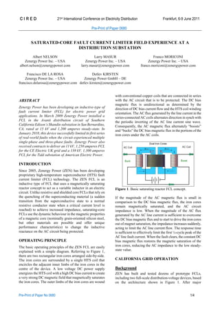
1. C I R E D 21st International Conference on Electricity Distribution Frankfurt, 6-9 June 2011
Pre-Print of Paper 0680
Pre-Print of Paper No 0680 1/4
SATURATED-CORE FAULT CURRENT LIMITER FIELD EXPERIENCE AT A
DISTRIBUTION SUBSTATION
Albert NELSON Larry MASUR Franco MORICONI
Zenergy Power Inc. – USA Zenergy Power Inc. – USA Zenergy Power Inc. – USA
albert.nelson@zenergypower.com larry.masur@zenergypower.com franco.moriconi@zenergypower.com
Francisco DE LA ROSA Detlev KIRSTEN
Zenergy Power Inc. – USA Zenergy Power GmbH – DE
francisco.delarosa@zenergypower.com detlev.kirsten@zenergypower.com
ABSTRACT
Zenergy Power has been developing an inductive-type of
fault current limiter (FCL) for electric power grid
applications. In March 2009 Zenergy Power installed a
FCL in the Avanti distribution circuit of Southern
California Edison’s Shandin substation in San Bernardino,
CA, rated at 15 kV and 1,200 amperes steady-state. In
January 2010, this device successfully limited its first series
of real-world faults when the circuit experienced multiple
single-phase and three-phase faults. Zenergy Power also
received contracts to deliver an 11 kV, 1,250 amperes FCL
for the CE Electric UK grid and a 138 kV, 1,300 amperes
FCL for the Tidd substation of American Electric Power.
INTRODUCTION
Since 2005, Zenergy Power (ZEN) has been developing
proprietary high-temperature superconductor (HTS) fault
current limiter (FCL) technology. The ZEN FCL is an
inductive type of FCL that uses a magnetically saturating
reactor concept to act as a variable inductor in an electric
circuit. Unlike resistive and shielded core FCLs that rely on
the quenching of the superconducting material (a sudden
transition from the superconductive state to a normal
resistive conductor state when a critical current level is
reached) to achieve increased impedance, saturating-core
FCLs use the dynamic behaviour in the magnetic properties
of a magnetic core (nominally grain-oriented silicon steel,
but other materials are possible and offer unique
performance characteristics) to change the inductive
reactance on the AC circuit being protected.
OPERATING PRINCIPLE
The basic operating principles of the ZEN FCL are easily
explained with a simple diagram. Referring to Figure 1,
there are two rectangular iron cores arranged side-by-side.
The iron cores are surrounded by a single HTS coil that
encircles the adjacent inner limbs of the iron cores in the
centre of the device. A low voltage DC power supply
energizes the HTS coil with a high DC bias current to create
a very strong DC magnetic field that magnetically saturates
the iron cores. The outer limbs of the iron cores are wound
with conventional copper coils that are connected in series
with the AC circuit that is to be protected. The DC bias
magnetic flux is unidirectional as determined by the
direction of DC bias current flow and the HTS coil winding
orientation. The AC flux generated by the line current in the
series-connected AC coils alternates direction in synch with
the periodic inverting of the AC line current sine wave.
Consequently, the AC magnetic flux alternately “boosts”
and “bucks” the DC bias magnetic flux in the portions of the
iron cores under the AC coils.
Figure 1. Basic saturating reactor FCL concept.
If the magnitude of the AC magnetic flux is small in
comparison to the DC bias magnetic flux, the iron cores
remain magnetically saturated, and the AC circuit
impedance is low. When the magnitude of the AC flux
generated by the AC line current is sufficient to overcome
the DC bias magnetic flux and to start to drive the iron cores
out of magnet saturation, the impedance increases suddenly,
acting to limit the AC line current flow. The response time
is sufficient to effectively limit the first ¼-cycle peak of the
AC line fault current. When the fault clears, the constant DC
bias magnetic flux restores the magnetic saturation of the
iron cores, reducing the AC impedance to the low steady-
state value.
CALIFORNIA GRID OPERATION
Background
ZEN has built and tested dozens of prototype FCLs,
including two full-scale distribution-voltage devices, based
on the architecture shown in Figure 1. After major
2. C I R E D 21st International Conference on Electricity Distribution Frankfurt, 6-9 June 2011
Pre-Print of Paper 0680
Pre-Print of Paper No 0680 2/4
refurbishment and modification following extensive testing,
the second of these full-scale FCLs was installed in a field
demonstration in the Avanti circuit of the Southern
California Edison (SCE) Shandin Substation located in San
Bernardino, CA, as shown in Figure 2.
Figure 2. The CEC FCL installed at the SCE Shandin
Substation in San Bernardino, California, USA.
This comprehensive field demonstration, which ran from
March 2009 until October 2010, was partially sponsored by
both the California Energy Commission (CEC) and the U.S.
Department of Energy (DOE), with significant in-kind
support by SCE, and was the first instance of a HTS FCL
being used in commercial service in the U.S. electric grid.
The Avanti circuit, also known as the “Circuit of the
Future,” is a specially configured and instrumented
distribution circuit serving residential and commercial
customers that is used by SCE, DOE and CEC to test and
evaluate promising “smart grid” and grid modernization
technologies. The focus of the demonstration project was
two-fold. The first objective was to establish that ZEN
could design and qualify a FCL to a precise operational
performance specification defined by SCE. The second
objective was to thoroughly evaluate the operations and
maintenance considerations associated with the use of a
HTS FCL in commercial service and to define the
requirements and protocols for widespread adoption of HTS
FCLs by electric utilities. The demonstration programwas a
complete success on both counts.
The “Avanti” FCL was nominally a 15 kV class (110 kV
BIL), 1200 amperes rms, 60-Hz device that was designed to
limit a 23 kA rms symmetric prospective fault by at least
20% while producing no more than 70 V back-emf at rated
steady-state current). The FCL was subjected to extensive
full-power (rated voltage and current) testing, fault testing,
and standards testing at Powertech Laboratories, Surrey,
B.C., Canada in October 2008, and a second set of high-
voltage electrostatics acceptance testing (lighting impulse,
chopped-wave, voltage withstand, and partial discharge)
was performed at SCE’s laboratories in Westminster,
California in December 2008. In the absence of accepted
industry standards for FCLs, a comprehensive test plan
based on IEEE standards for transformers and series
reactors [1-3] was developed in collaboration with SCE and
NEETRAC1
. In all, 65 separate tests events were
performed, including 32 full-power fault tests with first peak
fault current levels up to 59 kA.
Fault tests included individual fault events of 20-30 cycles
duration, as well as multiple fault events in rapid sequence
(to simulate automatic re-closer operation) and extended
fault events of up to 82 cycles duration (to simulate primary
protection failure scenarios). The design, development and
testing of the FCL has been extensively documented in
several papers [4-5].
Figure 3. Current limiting behavior of the ZEN FCL.
Operating Experience
The operations and maintenance experience gained and the
resulting protocols for the design, installation, control,
monitoring, and employment of FCLs in the electric grid
were the most important results of the “Avanti” FCL
demonstration. The operating environment at the Shandin
substation was a severe, U.S. southwest desert environment
with hot (daytime temperatures well in excess of 40 °C),
dry, dusty, high-wind conditions. Additionally, a residential
neighbourhood located nearby imposed severe ambient
noise requirements. The FCL performed well throughout the
demonstration, but several significant modifications were
made in collaboration with SCE. Significant observations
from the demonstration project include:
The enclosure environmental conditions must be
maintained within a narrow band for the reliability of
the control, instrumentation, cryogenic refrigeration
and DC power supply equipment – additional air
conditioning was installed in the FCL enclosure to
satisfy hot-day cooling requirements.
Air-cooled cryogenic refrigerators were satisfactorily
employed (with sufficient enclosure air conditioning),
but water-cooled cryogenic refrigerators may be more
robust in the field.
A sub-cooled liquid nitrogen re-condensing cryogenic
system was successfully employed. Current FCLs will
use a “dry-type” conduction-cooling cryogenic system
free of liquid cryogens.
The FCL control system is able to shut itself down in
1
National Electric Energy Testing Research Applications
Center, The Georgia Technical University, Atlanta,
Georgia, USA.
3. C I R E D 21st International Conference on Electricity Distribution Frankfurt, 6-9 June 2011
Pre-Print of Paper 0680
Pre-Print of Paper No 0680 3/4
the event of loss of station power – several substation
blackouts were experienced – and to automatically
restart when station power is restored, including the
restoration and stabilization of cryogenic refrigeration.
A UPS was installed to provide control,
instrumentation and DC bias current for up to two
hours during station outages.
While multiple channels of FCL system “health” data
were provided, SCE desired a “watch-dog” monitoring
system that provided a “Go” (all systems normal) or a
“No-Go” (some system off-specification) with an
automatic bypass switch to remove the FCL from
service in the event of a “No-Go” condition.
The FCL control system was successfully integrated
through a secure Ethernet connection into the SCE
SCADA system; a MODBUS control scheme enabled
secure, real-time monitoring and operation from the
SCE Control Room.
If the FCL is being relied upon for system protection,
the system must be configurable (through temporary
buss-splitting, for example) to control fault duty levels
in the event the FCL must be removed for maintenance
or repair.
Saturated-core FCLs as small inductors during steady-
state conditions and large inductors during fault
conditions must be evaluated for compatibility with
existing circuit resistance and capacitance values to
ensure voltage stability on the protected circuit – a
separate paper discusses this requirement [6].
The effects of saturated core FCLs on circuit breaker
transient recovery voltage must be evaluated to ensure
adequate rating of circuit breakers and determination of
maximum allowable interrupt currents – a separate
paper discusses this requirement [7].
On January 14, 2010 the FCL experienced its first-ever in-
grid fault. Based on the voltage data located at the load side
of the FCL, as shown in Figure 4, the event evolved from a
phase-to-phase fault, to a three-phase fault, to a temporary
recovery, to a phase-to-phase fault, to another three-phase
fault, ending with an open line and clearing. This very
unusual, mostly symmetrical, multi-fault event occurred
over a three-second period. Physically the event was
initiated by the overhead conductors of A and B phases
slapping together during high wind conditions near the end
of the Avanti Circuit. This phase-to-phase fault lasted about
250 milliseconds, when Phase C also faulted, thus evolving
into a three-phase fault, lasting about half a second. The air
insulation recovered its full strength for about one second,
but then the conductors of phases A and B again arced to
each other for about three quarters of a second. The arc was
about to be extinguished at this time; however, Phase C also
arced, becoming another three-phase fault. The event ended
about a quarter of a second later when Phase B conductor
opened, dropped to the ground, and the circuit was
eventually cleared. During this sequence of events the FCL
operated as designed and limited the fault current.
Figure 4. Multiphase sequence of fault events lasting over a
three second period.
DEVELOPMENT OF COMPACT FCL
Despite the unqualified success of the “Avanti” FCL
demonstration project, the large size and weight of the air-
dielectric, closed-core FCL architecture relative to its
electrical power rating challenged the economic value
proposition at distribution voltages. At the same time, the
air-dielectric design complicated scaling-up the device to
higher voltages. In light of these observations, ZEN
conceived of an open-core FCL design that used an oil
dielectric and conventional transformer design and
manufacturing techniques to create a much smaller FCL
with greater fault limiting performance and much higher
voltage and power ratings. This new design was designated
the “Compact FCL.”
ZEN, with financial support from DOE and the
Consolidated Edison Company of New York (ConEdison),
built and tested four full-scale distribution-voltage Compact
FCL prototypes using different internal designs. A unique
feature of the Compact FCL is that there is no physical
interface between the “AC side” of the device (the line
current and voltage in the circuit being protected) and the
“DC side” of the device (the HTS DC bias coil and its
associated power supply). The AC coils and bus-work are
located inside a dielectric tank, and the HTS DC bias
magnets are placed in cryostats that surround the tank.
Another important design innovation is the use of “dry-
type” cryogenics to conductively cool the HTS coil without
the use of liquid nitrogen. Conduction cooling allows the
HTS coil to be cooled below the nitrogen freezing point,
thereby improving the performance of the HTS wire and
reducing the amount used in the magnets. “Dry-type”
conduction cooling also avoids concerns about large
volumes of liquid cryogens in confined spaces and potential
pressure vessel and stored energy. Figure 5 shows a
recently completed 15kV class FCL with two “dry-type”
conduction cooled coils surrounding an oil-filled dielectric
tank with the AC coils. This device is 75% smaller and
4. C I R E D 21st International Conference on Electricity Distribution Frankfurt, 6-9 June 2011
Pre-Print of Paper 0680
Pre-Print of Paper No 0680 4/4
lighter than the equivalent device shown in Figure 2.
Figure 5. Compact FCL with “dry-cooled” HTS magnets
surrounding an oil-filled dielectric tank with AC coils.
AMERICAN ELECTRIC POWER PROJECT
ZEN has entered into an agreement with American Electric
Power (AEP), Columbus, Ohio, to partner for the
demonstration of a 138 kV three-phase FCL as a part of
ZEN’s ongoing DOE-sponsored FCL development
program. A single-phase 138 kV FCL prototype will be
built and tested in the first half of 2011, and a three-phase
FCL demonstration unit will be built, tested and installed in
AEP’s Tidd substation located near Steubenville, Ohio in
early 2012. This device will be designed to operate at 1.3
kA steady state and reduce an approximate 20 kA
prospective fault by 43% and instantaneously recover under
load. The device will be installed on the low side of the 345
kV to 138 kV transformer and will protect the 138 kV
feeder.
Figure 6. Comparison of voltage drop between a current
limiting reactor and the ZEN FCL.
AEP presently uses a conventional 3.8 Ω current limiting
reactor to protect the circuit from excess fault currents. This
reactor causes a 6% voltage drop on a base load of
320 MVA. When the ZEN FCL is installed the circuit will
have the same amount of fault current protection; however
the steady-state voltage drop will be 75% less – only 1.5%
on a base load of 320 MVA. Please see Figure 6.
Acknowledgments
The FCL at SCE´s Shandin substation was partially
sponsored by both the California Energy Commission
(CEC) and the U.S. Department of Energy (DOE), with
significant in-kind support by SCE.
The compact FCL designs were developed and tested with
financial support from DOE and the Consolidated Edison
Company of New York (ConEdison),
The 138kV three-phase FCL is part of ZEN’s ongoing
DOE-sponsored FCL development program and partnered
by American Electric Power (AEP), Columbus, Ohio.
REFERENCES
[1] IEEE Std C57.16-1996. IEEE Standard Requirements,
Terminology, and Test Code for Dry-Type Air-core
Series-Connected Reactors.
[2] IEEE Std C57-12.01-2005. IEEE Standard General
Requirements for Dry-Type Distribution and Power
Transformers, Including Those with Solid-Cast and/or
Resin Encapsulated Windings
[3] IEEE Standard Test Code for Liquid-Immersed
Distribution, Power and Regulating Transformers”,
IEEE Std. C57.12.90-1999. M. Young, 1989, The
Technical Writers Handbook, University Science, Mill
Valley, CA, USA.
[4] Moriconi, F., Koshnick, N., De La Rosa, F., Singh, A.,
“Modelling and Test Validation of a 15kV 24MVA
Superconducting Fault Current Limiter,” Proceedings
of the 2010 IEEE PES Transmission and Distribution
Conference, April 19-22, 2010, New Orleans, LA,
USA.
[5] Moriconi, F., De La Rosa, F., Singh, A., Chen, B.,
Levitskaya, M., Nelson, A., “An Innovative Compact
Saturable-Core HTS Fault Current Limiter –
Development, Testing and Application to
Transmission-Class Networks,” Proceedings of the
2010 IEEE PES General Meeting, July 25-29, 2010,
Minneapolis, MN, USA.
[6] Clarke, C., Moriconi, F., Singh, A., Kamiab, A., Neal,
R., Rodriguez, A., De La Rosa, F., Koshnick, N.,
“Resonance of A Distribution Feeder with a Saturable
Core Fault Current Limiter,” Proceedings of the 2010
IEEE PES Transmission and Distribution Conference,
April 19-22, 2010, New Orleans, LA, USA.
[7] Lopez-Roldan, J., Price, A.C., De La Rosa, F.,
Moriconi, F., “Analysis of the Effect of a Saturable-
Core HTS Fault Current Limiter on the Circuit
Breaker Transient Recovery Voltage,” submitted to
the Proceedings of the 2011 IEEE PES General
Meeting, July 24-29, Detroit, MI, USA.