1. PRIMARY RESERVE ESTIMATION FROM INDUSTRIALAND
COMMERCIAL SMART LOADS
Diptargha Chakravorty, Balarko Chaudhuri, Ron Hui, and Goran Strbac
Control and Power Group, Department of Electrical and Electronic Engineering, Imperial College London
2015 IEEE PES General Meeting
RESEARCH OBJECTIVE
• Characterizing industrial and commercial loads suitable for smart load
application.
• Analytically estimating primary reserve available from candidate smart
loads.
• Aggregation of smart load reserve at each node at transmission level
(275/400 kV) considering actual share of different load types within each
sector.
• Study aggregated impact of several smart loads in stabilization of grid
frequency after large loss of infeed.
Fig. 1: Activation of reserves (source:Dynamic Frequency Control Support by Energy Storage to
Reduce the Impact of Wind and Solar Generation on Isolated Power System’s Inertia)
Fig. 2: Smart Load configuration
SMART LOAD
Smart load comprises of a controlled voltage source (Electric Spring) in
series with a non-critical load, as shown in Fig. 2. The injected series voltage
(VESES) is controlled to regulate the mains voltage while allowing the
voltage across the non-critical load (VNC) and consequently its active power
consumption to vary, thereby, collectively contributing towards system
frequency support.
A. Concept
TEST NETWORK
Fig. 4: 67 machine GB reduced model
• Capability increases as
kpv varies from 0.5 to 2,
kqv maintained constant.
• VNC-MAX and VNC-MIN limited
to ±20%.
• Converter rating limited to
20% of non-critical load
nominal rating.
• Capability increases as VC
varied from 0.95 to 1.05
p.u.
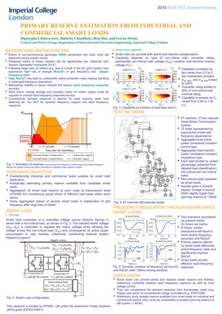
FREQUENCY REGULATION THROUGH AGGREGATED
SMART LOADS
Fig. 5: Dynamic variation of frequency (at bus 22)
and RoCoF (with 100ms moving window)
CONCLUSION
• Smart loads can provide active and reactive power reserve and thereby,
collectively contribute towards rapid frequency response as well as local
voltage control.
• They can complement the demand response from thermostatic loads (e.g.
fridges) and action of conventional voltage controllers (e.g. STATCOM).
• Preliminary study reveals reserve available from smart loads (in industrial and
commercial sectors only) could be comparable to present spinning reserve of
GB system (1.8GW).
BACKGROUND AND MOTIVATION
• Extent of non-synchronous generator (NSG) penetration like solar, wind will
determine future system inertia.
• Predicted inertia of future network will be significantly low. (National Grid
System Operability Framework 2014 )
• Following large loss of infeed (e.g. due to a fault in the DC grid) system may
experience high rate of change (RoCoF) of grid frequency and deeper
frequency nadir.
• High RoCoF may lead to undesirable mains protection relay tripping resulting
in prolonged frequency depression.
• Maintaining stability in future network will require rapid frequency response
services.
• Wind farms, energy storage and possibly, loads (of certain types) could be
required to provide rapid frequency response service.
• Conventional demand response is tailored for peak shaving, peak load
deferring etc. but NOT for dynamic frequency support and rapid frequency
response.
This research is funded by EPSRC, UK under the Autonomic Power Systems
(APS) grant (EP/I031650/1)
B. Smart load capability
IFA
1
IFA
2
Z 3Z 2
Z 1
Z 4 Z 5
Z 6 Z 7
Z
10
Z
10
Z
11
Z 9Z 8
Z
12
Z
13
Z
14A
Z
14
Z
15
Z
16Z
17
Z
18
Z
20
Z
21
Z
19
Z
22
Z
23
Z
24
Z
16
Z
25A
Z
25
Z
26
Z
27E
Z
27W
Z
S9
Z
28
Z
29
Z
30 Z
31
Z
33
Z
32
• Smart load can provide both active and reactive compensation.
• Capability depends on type of non-critical load, converter rating,
permissible non-critical load voltage (VNC) variation and terminal (mains)
voltage (VC).
Fig. 3: Capability as function of load type and VC
• 67 machine, 37 bus reduced
Great Britain Transmission
System.
• 37 loads represented by
exponential model with
frequency dependence.
• Aggregated load active
power considered constant
current type.
• Aggregated load reactive
power considered constant
impedance type.
• Each load divided by certain
percentage (obtained from
detailed load classification)
into critical and non-critical
loads.
• Non-critical loads operated
as smart loads.
• Nuclear plant in Zone22
tripped. Outage is around
2GW, slightly higher than
spinning reserve of 1.8GW.
• Two scenarios considered
(a) present inertia
(b) future low inertia.
• In future, similar
disturbance will result in
more severe frequency
excursion and RoCoF.
• Primary reserve offered
by smart loads effectively
arrest frequency nadir and
significantly improve
RoCoF.
• Smart loads provide
effective rapid frequency
response.
Converter #1
VES ES
PES = VESIcosES
QES = VESIsinES
VC
Supply mains
I0
PSL=PNC PES
QSL=QNC QES
Converter #2
Vdc and Q(=0) control VES and ES control
PES ≈ VESIcosES
C
VNC
I0
Non-critical load
PNC=PNC0(VNC/VNC0)kpv
QNC=QNC0(VNC/VNC0)kqv
20 25 30 35
49.2
49.4
49.6
49.8
50
Time(sec)
Frequency(Hz)
(a) present inertia
noSL
SL
20 25 30 35
49.2
49.4
49.6
49.8
50
Time(sec)
Frequency(Hz)
(b) future low inertia
20 22.5 25
-0.6
-0.4
-0.2
0
0.2
-0.58
-0.23
Time(sec)
RoCoF(Hz/sec)
(c) present inertia
20 22.5 25
-1
-0.8
-0.6
-0.4
-0.2
0
0.2
-0.95
-0.29
Time(sec)
RoCoF(Hz/sec)
(d) future low inertia