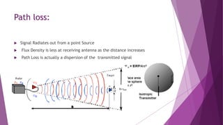
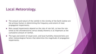
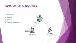
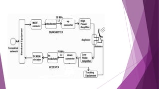
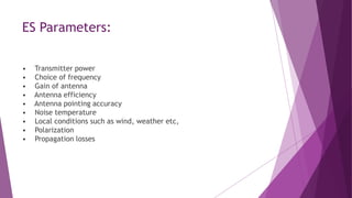
EARTH STATION
PARAMATERS
JENIL.J
What is Earth Station?
 Any transmitting or receiving system which sends or
receives signal to and from satellite
 Earth station is a vital element in any satellite
communication network.
 The function of an earth station is to receive information
from or transmit information to, the satellite network in the
most cost-effective and reliable manner while retaining the
desired signal quality.
 The design of earth station configuration depends upon
many factors and its location
Earth Station Subsystems
 Transmitter
 Receiver
 Antenna
 Tracking Equipment
ES Parameters:
• Transmitter power
• Choice of frequency
• Gain of antenna
• Antenna efficiency
• Antenna pointing accuracy
• Noise temperature
• Local conditions such as wind, weather etc,
• Polarization
• Propagation losses
G/T Ratio:
 G/T is Gain / Noise Temperature
 G/T = Antenna Gain (dB) - System Noise Temperature (dB) [10
Log(Tsys/1°K )]
 Signal at the receiving antenna is increased by the antenna gain
 Subtract out the System Noise Temperature
 Result is signal level with respect to Thermal noise
Calculating G/T:
 TSYS = TA + TLNA
 TA is the antenna noise temperature
 TLNA is the LNA noise temperature (Receiver Noise)
 Antenna: TA = 43° K, Gain = 38 dB
 LNA: TLNA = 51° K
TSYS = 43 ° + 51 ° = 94 ° K
 G/T = Antenna Gain (dB) - 10 Log(Tsys/1°K )
 G/T = 38dB –19.7dB = 18.3 dB -
Noise:
 There are two main sources of noise in a satellite system:
 Noise arising in the satellite and earth-station equipment
 Noise collected by the satellite and earth-station antennas
 Noise power radiated by the Earth is collected by the side lobes of the earth-
station antenna and the main beam of the satellite antenna.
 Noise power N is related to an equivalent noise temperature by the
expression:
N = k . T . B watts
Where, K is Boltzmann's constant (1.38 x 10⁻²³ J/K)
B is the bandwidth in which the noise is measured (in Hz)
Radiated Power:
 EIRP = Transmitter Output Power + Antenna Gain
 EIRP includes the effects of:
1. Antenna Gain
2. Antenna Efficiencies
3. Transmitter Output Power
4. Coupling and Wave guide Losses, Etc.
 Once the EIRP is known, no additional information about the
transmitter is required.
 EIRP information assumes the transmitter is pointed directly at the
receiver -
Transmitted Power
 Typical Required EIRP = 42 dBW / 4kHz (Clear Sky)
Determined by the satellite operator
 Assume Signal Bandwidth = 8MHz + 33 dB (with respect to 4kHz) i.e
10Log(8MHz/4kHz)
 For 8MHz the required EIRP = + 75 dBW
 Antenna size
1. 10 Meter antenna @ 6 GHz 53.3 dB of Gain
 Misc Loss = 4 dB
 Pout= +75 dBW -53.3 dB + 4 dB = +25.7dBW
 Required transmitter Pout = 372 Watts
Path loss:
 Signal Radiates out from a point Source
 Flux Density is less at receiving antenna as the distance increases
 Path Loss is actually a dispersion of the transmitted signal
Calculation of Path loss:
 Path Loss in dB = 10 Log(PL)
 Path Loss is related to Number of Wave Lengths
 Path Loss proportional to (D / λ) 2
 Example
 Frequency: 14GHz
 Lambda (λ) = 0.021429 Meters
 Distance: 22,300 Miles (35,888 kM)
 Path Loss: 206.46 dB
Some Effects.,
 Operating frequency
 Antenna Elevation Angle
 Polarization
 ES Altitude
 ES Noise Temperature
 Local Meteorology
 Climate
 Operating Frequency.
With the exception of signal attenuation by gaseous absorption
lines, the severity of tropospheric impairments increases with frequency.
 Earth Station Altitude.
Because less of the troposphere is included in paths from higher
altitude sites, impairments are less.
 Earth Station Noise Temperature.
This determines the relative contribution of sky noise
temperature to system noise temperature~ and thus the effect of sky noise on
the downlink signal-to-noise ratio.
Antenna Elevation Angle and Polarization.
 The length of the part of the propagation path passing through the
troposphere varies inversely with elevation angle.
 Accordingly, propagation losses, noise, and depolarization also increase with
decreasing elevation angle.
 Rain attenuation is slightly polarization-sensitive.
 Depolarization is also polarization-sensitive, with circular polarization being
the most susceptible.
Local Meteorology.
 The amount and nature of the rainfall in the vicinity of the Earth station are
the primary factors in determining the frequency and extent of most
propagation impairments.
 Rain caused impairments depend on the rate of rain fall, so how the rain
tends to fall (thunderstorms versus steady showers) is as important as the
cumulative amount of rainfall.
 The type and extent of cloud cover, and local humidity characteristics are
other meteorological factors that determine the magnitude of propagation
impairments.
Earth station Parameters

Earth station Parameters

  • 1.
  • 2.
    What is EarthStation?  Any transmitting or receiving system which sends or receives signal to and from satellite  Earth station is a vital element in any satellite communication network.  The function of an earth station is to receive information from or transmit information to, the satellite network in the most cost-effective and reliable manner while retaining the desired signal quality.  The design of earth station configuration depends upon many factors and its location
  • 3.
    Earth Station Subsystems Transmitter  Receiver  Antenna  Tracking Equipment
  • 5.
    ES Parameters: • Transmitterpower • Choice of frequency • Gain of antenna • Antenna efficiency • Antenna pointing accuracy • Noise temperature • Local conditions such as wind, weather etc, • Polarization • Propagation losses
  • 6.
    G/T Ratio:  G/Tis Gain / Noise Temperature  G/T = Antenna Gain (dB) - System Noise Temperature (dB) [10 Log(Tsys/1°K )]  Signal at the receiving antenna is increased by the antenna gain  Subtract out the System Noise Temperature  Result is signal level with respect to Thermal noise
  • 7.
    Calculating G/T:  TSYS= TA + TLNA  TA is the antenna noise temperature  TLNA is the LNA noise temperature (Receiver Noise)  Antenna: TA = 43° K, Gain = 38 dB  LNA: TLNA = 51° K TSYS = 43 ° + 51 ° = 94 ° K  G/T = Antenna Gain (dB) - 10 Log(Tsys/1°K )  G/T = 38dB –19.7dB = 18.3 dB -
  • 8.
    Noise:  There aretwo main sources of noise in a satellite system:  Noise arising in the satellite and earth-station equipment  Noise collected by the satellite and earth-station antennas  Noise power radiated by the Earth is collected by the side lobes of the earth- station antenna and the main beam of the satellite antenna.  Noise power N is related to an equivalent noise temperature by the expression: N = k . T . B watts Where, K is Boltzmann's constant (1.38 x 10⁻²³ J/K) B is the bandwidth in which the noise is measured (in Hz)
  • 9.
    Radiated Power:  EIRP= Transmitter Output Power + Antenna Gain  EIRP includes the effects of: 1. Antenna Gain 2. Antenna Efficiencies 3. Transmitter Output Power 4. Coupling and Wave guide Losses, Etc.  Once the EIRP is known, no additional information about the transmitter is required.  EIRP information assumes the transmitter is pointed directly at the receiver -
  • 10.
    Transmitted Power  TypicalRequired EIRP = 42 dBW / 4kHz (Clear Sky) Determined by the satellite operator  Assume Signal Bandwidth = 8MHz + 33 dB (with respect to 4kHz) i.e 10Log(8MHz/4kHz)  For 8MHz the required EIRP = + 75 dBW  Antenna size 1. 10 Meter antenna @ 6 GHz 53.3 dB of Gain  Misc Loss = 4 dB  Pout= +75 dBW -53.3 dB + 4 dB = +25.7dBW  Required transmitter Pout = 372 Watts
  • 11.
    Path loss:  SignalRadiates out from a point Source  Flux Density is less at receiving antenna as the distance increases  Path Loss is actually a dispersion of the transmitted signal
  • 12.
    Calculation of Pathloss:  Path Loss in dB = 10 Log(PL)  Path Loss is related to Number of Wave Lengths  Path Loss proportional to (D / λ) 2  Example  Frequency: 14GHz  Lambda (λ) = 0.021429 Meters  Distance: 22,300 Miles (35,888 kM)  Path Loss: 206.46 dB
  • 14.
    Some Effects.,  Operatingfrequency  Antenna Elevation Angle  Polarization  ES Altitude  ES Noise Temperature  Local Meteorology  Climate
  • 15.
     Operating Frequency. Withthe exception of signal attenuation by gaseous absorption lines, the severity of tropospheric impairments increases with frequency.  Earth Station Altitude. Because less of the troposphere is included in paths from higher altitude sites, impairments are less.  Earth Station Noise Temperature. This determines the relative contribution of sky noise temperature to system noise temperature~ and thus the effect of sky noise on the downlink signal-to-noise ratio.
  • 16.
    Antenna Elevation Angleand Polarization.  The length of the part of the propagation path passing through the troposphere varies inversely with elevation angle.  Accordingly, propagation losses, noise, and depolarization also increase with decreasing elevation angle.  Rain attenuation is slightly polarization-sensitive.  Depolarization is also polarization-sensitive, with circular polarization being the most susceptible.
  • 17.
    Local Meteorology.  Theamount and nature of the rainfall in the vicinity of the Earth station are the primary factors in determining the frequency and extent of most propagation impairments.  Rain caused impairments depend on the rate of rain fall, so how the rain tends to fall (thunderstorms versus steady showers) is as important as the cumulative amount of rainfall.  The type and extent of cloud cover, and local humidity characteristics are other meteorological factors that determine the magnitude of propagation impairments.