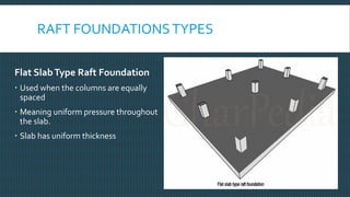
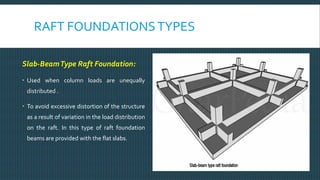
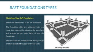
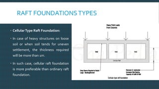
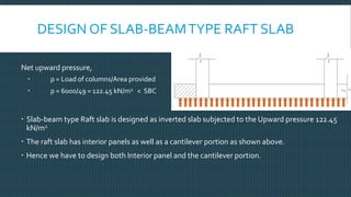
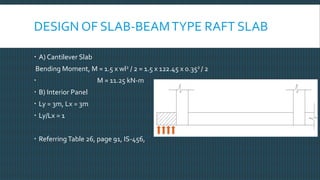
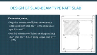
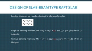
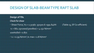
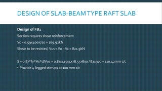
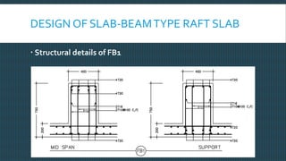
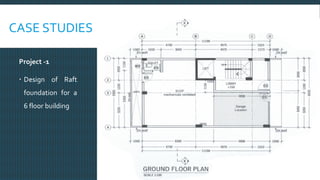
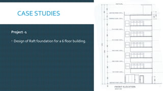
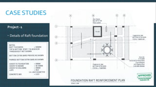
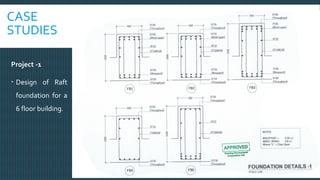
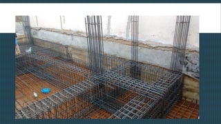
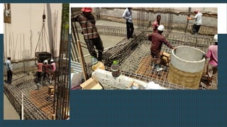
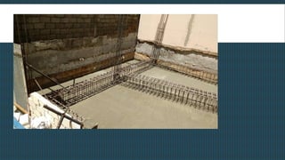
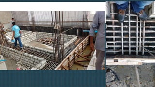
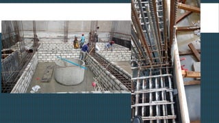
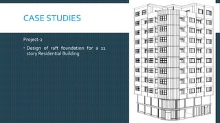
DESIGN CONCEPTS IN RAFT FOUNDATION FOR HIGH RISE
BUILDINGS
DEPARTMENT OF CIVIL ENGINEERING
V.S SATHEESH
ASSOCIATE PROFESSOR
KUPPAM ENGINEERINGCOLLEGE
RAFT FOUNDATIONS
Also known as Mat foundations
 It is a continuous slab resting on the soil
 Extends over the entire footprint of the building thereby supporting the building
and transferring its weight to the ground.
 Best suitable when have a basement floor (High rise structures)
RAFT FOUNDATIONS
When do we need a raft foundation?
 Bearing capacity of the soil is low
 Load to be transferred to the ground is high
 Deep foundation becomes uneconomical
 More number of columns
 The total footing area is greater than 50% of the building area
RAFT FOUNDATION
Advantages
 Supports large number of columns
 Helps overcome differential settlement
 Distributes the loads on a wider area thereby not exceeding allowable
bearing capacity
 The only shallow foundation to carry heavy loads
 Can carry lateral loads too
 Resists uplift pressure
RAFT FOUNDATIONSTYPES
Flat SlabType Raft Foundation
 Used when the columns are equally
spaced
 Meaning uniform pressure throughout
the slab.
 Slab has uniform thickness
RAFT FOUNDATIONSTYPES
Slab-BeamType Raft Foundation:
 Used when column loads are unequally
distributed .
 To avoid excessive distortion of the structure
as a result of variation in the load distribution
on the raft. In this type of raft foundation
beams are provided with the flat slabs.
RAFT FOUNDATIONSTYPES
 Slab-BeamType Raft Foundation:
 The beams add stiffness to the raft foundation.
 The foundation slabs are reinforced with two
more steel meshes. One placed on the lower face
and another at the upper faces of the raft
foundation.
 The raft beams are reinforced with strong stirrups
and bars placed at the upper and lower faces.
RAFT FOUNDATIONSTYPES
 CellularType Raft Foundation:
 In case of heavy structures on loose
soil or when soil tends for uneven
settlement, the thickness required
will be more than 1m.
 In such case, cellular raft foundation
is more preferable than ordinary raft
foundation.
RAFT FOUNDATIONSTYPES
 CellularType Raft Foundation:
 Consists two slabs where a beam is
constructed of two slabs in both
directions forming hollow cellular raft
foundation.
 These foundations are highly rigid and
more economical than other
foundations in such type of poor soil
RAFT FOUNDATIONSTYPES
Piled Raft foundation
 When the soil so weak that there is an
excessive settlement of the raft slab then Raft
slab is laid on the piles.
 Load is carried by the raft slab and settlement
is resisted by piles
DESIGN OF RAFT SLAB
Two approaches
 Rigid foundation approach
 Flexible foundation approach
Rigid Approach - In rigid foundation approach, it is presumed that raft is rigid enough to
bridge over non-uniformities of soil structure. Pressure distribution is considered to be
either uniform or varying linearly.
(a) Inverted floor system (b) Combined footing approach
 In rigid rafts, differential settlements are comparatively low but bending moment and
shear forces to which raft is subjected are considerably high
DESIGN OF RAFT SLAB
Flexible Approach
 In this approach, raft distributes the load in the area immediately surrounding the
column depending upon the soil characteristics.
 Differential settlements are comparatively larger but bending moments and shear
forces are comparatively low.Two approaches
(a) Flexible plate supported on elastic foundation, i.e., Hetenyi'sTheory
(b) Foundation supported on bed of uniformly distributed elastic springs with a spring
constant determined using coefficient of sub-grade reaction. Each spring is presumed
to behave independently, i.e., Winklers's foundation
DESIGN OF RAFT SLAB
Pressure distributed under the raft
(1) The nature of the soil below the raft
(2) The nature of the foundation, i.e., whether rigid, flexible or soft
(3) Rigidity of the super-structure
(4) The quantum of loads and their relative magnitude
(5) Presence of adjoining foundation
(6) Size of raft
(7) Time at which pressure measurements are taken
DESIGN OF RAFT SLAB
DESIGN OF RAFT SLAB
Settlement of Raft Slab
 The total settlement under the raft foundation can be considered to be made up
of three components, i.e.,
S = Sd+Sc+Ss
Where,
Sd is the immediate or distortion settlement
Sc the consolidation settlement and
Ss is the secondarycompression settlement
DESIGN OF SLAB-BEAMTYPE RAFT SLAB
Design of Slab-beam type raft slab (Inverted slab)
 The most common approach in Medium rise residential/commercial buildings
 The raft slab is designed as an inverted slab
 The uplift pressure is the loading on the slab, for which BM and SFs are
calculated
 The raft beams stiffen the raft slab
 Raft beams are designed as inverted floor beams subjected to uplift pressure
DESIGN OF SLAB-BEAMTYPE RAFT SLAB
 Area of the slab will be equal
to footprint of the building.
 Cantilever portions are not
always necessary, depends on
the area required
DESIGN OF SLAB-BEAMTYPE RAFT SLAB
 Example for discussion
 Design a raft footing for the
foundation plan shown. Assume SBC
150kN/m2
 C1 – 300x300 – 800 kN
 C2 – 300x300 – 600 kN
DESIGN OF SLAB-BEAMTYPE RAFT SLAB
Solution : -
 Calculation of column loads
 Load from column C1 = 3 x 800 = 2400 kN
 Load from column C2 = 6 x 600 = 3600 kN
 Total load on Foundation = 6000 kN
 Self weight of Foundation, 10% = 600 kN
 Total load, w = 6600 kN
 Area of footing required, A = 6600/150 = 44 m2 - SBC = 150kN/ m2
 Footprint area of the grid = 6.3x6.3 = 39.69 m2 < Area required.
DESIGN OF SLAB-BEAMTYPE RAFT SLAB
 Adopt a size of 7mx7m = 49m2
 Since, the grid cannot be changed, Extend
the raft on the edges on all four sides as
shown in the figure.
 Now this area would be sufficient.
Sadat Ali Khan, The Maldives National University
DESIGN OF SLAB-BEAMTYPE RAFT SLAB
Net upward pressure,
 p = Load of columns/Area provided
 p = 6000/49 = 122.45 kN/m2 < SBC
 Slab-beam type Raft slab is designed as inverted slab subjected to the Upward pressure 122.45
kN/m2
 The raft slab has interior panels as well as a cantilever portion as shown above.
 Hence we have to design both Interior panel and the cantilever portion.
DESIGN OF SLAB-BEAMTYPE RAFT SLAB
 A) Cantilever Slab
Bending Moment, M = 1.5 x wl2 / 2 = 1.5 x 122.45 x 0.352 / 2
 M = 11.25 kN-m
 B) Interior Panel
 Ly = 3m, Lx = 3m
 Ly/Lx = 1
 Referring Table 26, page 91, IS-456,
DESIGN OF SLAB-BEAMTYPE RAFT SLAB
For Interior panels,
 Negative moment coefficients at continuous
edge along short span αx = -0.032, along longer
span αy = - 0.032
 Positive moment coefficients at midspan along
short span αx = -0.032, along longer span αy =
- 0.032
DESIGN OF SLAB-BEAMTYPE RAFT SLAB
 Bending Moments are calculated using the following formulae,
 Negative bending moment, Mx = My = 0.032 x1.5x 122.45 x 32 = 52.89 kN-m (at
supports)
 Positive bending moment, Mx = My = 0.024x1.5x122.45x 32 = 39.67 kN-m (at
Midspan)
DESIGN OF SLAB-BEAMTYPE RAFT SLAB
 Depth required, Mu = 0.138fck bd2
 52.89x106 = 0.138x20x1000d2
 d = 138.43 mm
 Adopt d = 150mm and a cover of 50mm, D = 200mm
Area of steel required,
For negative moment, Mu = 0.87 *fy *Ast (d-0.42Xu,max)
 52.89 x 106= 0.87 x 415 x Ast (150 – 0.42(0.48x150))
Ast = 1223.19 mm2
Using 16 dia bars, spacing required = 201x1000/1223.19 = 164.4mm
PlaceT16 @ 150mm c/c
Area of steel provided, Ast = 1340 mm2
DESIGN OF SLAB-BEAMTYPE RAFT SLAB
Similarly for positive moment,
Ast = 917.45 mm2
Using 16 dia bars, spacing required = 201x1000/917.45 = 219.08mm
PlaceT16 @ 150mm c/c
Area of steel provided, Ast = 1340 mm2
DESIGN OF SLAB-BEAMTYPE RAFT SLAB
Check for deflection
 Steel stress of service, fs = 0.58 * fy * 1223.19/1340 = 219.72 N/mm2
 Percentage steel provided is 0.67
 Referring fig.4, IS456, Modification factor is 1.4
 Minimum depth, d min = 3000/26/1.4 = 82 mm
 Allowable s/d ratio = 1.4x26 = 36.4
 Provided s/d ratio = 3000/200 = 15
Hence the section safe in deflection
DESIGN OF SLAB-BEAMTYPE RAFT SLAB
 Check for Shear
Shear force,Vu = 122.45 x 3/2 = 183kN
Shear stress,Tv =Vu/bd = 1.22N/mm2
Now, 100Ast/bd = 0.8933, Referring to table 19,
Design shear strength, k*Tc = 1.2 x 0.6 = 0.72 N/mm2
Shear reinforcement is required
Let’s provide bent-up bars,
Area of shear reinforcement, forVus = 1.22 – 0.72 = 0.5 N/mm2
Asv =Vus/(σsv*Sinα) = 0.5x1000x150/(230*sin45) = 461.15 mm2
ProvideT12 @ 200mm c/c
Check for cracking
 The steel provided is more than 0.12% of gross area
 Spacing is less than 3d
 Hence the section is safe
DESIGN OF SLAB-BEAMTYPE RAFT SLAB
 Design of Raft Beams
 Uplift pressure 122.45 kN/m2
 Load carried by foundation/raft beams is
shown in the figure beside.
 FB1 carries the load distributed on two
triangles,
 FB2 carries the load distributed on one
triangle and a portion of cantilever
Sadat Ali Khan, The Maldives National University
DESIGN OF SLAB-BEAMTYPE RAFT SLAB
Design of FB1
 Area of loading = (0.5x3x3)x2 = 9 m2
 Loading on the beam, w = 122.45x9/3 = 367.35kN/m
 Moment at supports, Mu = 1.5xwl2 / 10 = 1.5 x 367.35 x 32 /10 = 495.92 kN-m (Table-12)
 Moment at mid span, Mu = 1.5xwl2 / 12 = 1.5 x 367.35 x 32 /12 = 413.27 kN-m
 Depth of the beam, d min, Mu = 0.138fckbd2 , assuming b = 400mm
 d min = 670.22 mm,
 Adopt d = 720 mm, cover = 30mm
 Over all depth D = 750mm
DESIGN OF SLAB-BEAMTYPE RAFT SLAB
Design of FB1
Mu lim will be greater than Mu
Beam can be designed as singly reinforced
Ast reqd = 2322.17 mm2
 Provide 8-T20
 Ast Provided = 2512mm2
DESIGN OF SLAB-BEAMTYPE RAFT SLAB
Design of FB1
Check for shear
 Shear Force,Vu = 1.5x367. 35x3x0.6 =991.84kN (Table 13, SF Co-efficient)
τv = 661.23x1000/(300x800) = 4.132 N/mm2
100Ast/bd = 0.872
 τc = 0.59 N/mm2,τc max = 2.8 N/mm2
DESIGN OF SLAB-BEAMTYPE RAFT SLAB
Design of FB1
Section requires shear reinforcement
Vc = 0.59x400x720 = 169.92kN
Shear to be resisted,Vus =Vu –Vc = 821.9kN
S = 0.87*fy*As*d/Vus = 0.87x415x4x78.55x800 / 821920 = 110.42mm c/c
 Provide 4-legged stirrups at 100 mm c/c
DESIGN OF SLAB-BEAMTYPE RAFT SLAB
 Structural details of FB1
Sadat Ali Khan, The Maldives National University
CASE STUDIES
Project -1
 Design of Raft
foundation for a
6 floor building
Sadat Ali Khan, The Maldives National University
CASE STUDIES
Project -1
 Design of Raft foundation for a 6 floor building.
Sadat Ali Khan, The Maldives National University
CASE STUDIES
Project -1
 Details of Raft foundation
Sadat Ali Khan, The Maldives National University
CASE
STUDIES
Project -1
 Design of Raft
foundation for a
6 floor building.
Sadat Ali Khan, The Maldives National University
CASE STUDIES
 Project 1
CASE STUDIES
Project-2
 Design of raft foundation for a 11
story Residential Building
Sadat Ali Khan, The Maldives National University
Thank you….

CE-Raft-Foundation.pdf

  • 1.
    DESIGN CONCEPTS INRAFT FOUNDATION FOR HIGH RISE BUILDINGS DEPARTMENT OF CIVIL ENGINEERING V.S SATHEESH ASSOCIATE PROFESSOR KUPPAM ENGINEERINGCOLLEGE
  • 2.
    RAFT FOUNDATIONS Also knownas Mat foundations  It is a continuous slab resting on the soil  Extends over the entire footprint of the building thereby supporting the building and transferring its weight to the ground.  Best suitable when have a basement floor (High rise structures)
  • 3.
    RAFT FOUNDATIONS When dowe need a raft foundation?  Bearing capacity of the soil is low  Load to be transferred to the ground is high  Deep foundation becomes uneconomical  More number of columns  The total footing area is greater than 50% of the building area
  • 4.
    RAFT FOUNDATION Advantages  Supportslarge number of columns  Helps overcome differential settlement  Distributes the loads on a wider area thereby not exceeding allowable bearing capacity  The only shallow foundation to carry heavy loads  Can carry lateral loads too  Resists uplift pressure
  • 5.
    RAFT FOUNDATIONSTYPES Flat SlabTypeRaft Foundation  Used when the columns are equally spaced  Meaning uniform pressure throughout the slab.  Slab has uniform thickness
  • 6.
    RAFT FOUNDATIONSTYPES Slab-BeamType RaftFoundation:  Used when column loads are unequally distributed .  To avoid excessive distortion of the structure as a result of variation in the load distribution on the raft. In this type of raft foundation beams are provided with the flat slabs.
  • 7.
    RAFT FOUNDATIONSTYPES  Slab-BeamTypeRaft Foundation:  The beams add stiffness to the raft foundation.  The foundation slabs are reinforced with two more steel meshes. One placed on the lower face and another at the upper faces of the raft foundation.  The raft beams are reinforced with strong stirrups and bars placed at the upper and lower faces.
  • 8.
    RAFT FOUNDATIONSTYPES  CellularTypeRaft Foundation:  In case of heavy structures on loose soil or when soil tends for uneven settlement, the thickness required will be more than 1m.  In such case, cellular raft foundation is more preferable than ordinary raft foundation.
  • 9.
    RAFT FOUNDATIONSTYPES  CellularTypeRaft Foundation:  Consists two slabs where a beam is constructed of two slabs in both directions forming hollow cellular raft foundation.  These foundations are highly rigid and more economical than other foundations in such type of poor soil
  • 10.
    RAFT FOUNDATIONSTYPES Piled Raftfoundation  When the soil so weak that there is an excessive settlement of the raft slab then Raft slab is laid on the piles.  Load is carried by the raft slab and settlement is resisted by piles
  • 11.
    DESIGN OF RAFTSLAB Two approaches  Rigid foundation approach  Flexible foundation approach Rigid Approach - In rigid foundation approach, it is presumed that raft is rigid enough to bridge over non-uniformities of soil structure. Pressure distribution is considered to be either uniform or varying linearly. (a) Inverted floor system (b) Combined footing approach  In rigid rafts, differential settlements are comparatively low but bending moment and shear forces to which raft is subjected are considerably high
  • 12.
    DESIGN OF RAFTSLAB Flexible Approach  In this approach, raft distributes the load in the area immediately surrounding the column depending upon the soil characteristics.  Differential settlements are comparatively larger but bending moments and shear forces are comparatively low.Two approaches (a) Flexible plate supported on elastic foundation, i.e., Hetenyi'sTheory (b) Foundation supported on bed of uniformly distributed elastic springs with a spring constant determined using coefficient of sub-grade reaction. Each spring is presumed to behave independently, i.e., Winklers's foundation
  • 13.
    DESIGN OF RAFTSLAB Pressure distributed under the raft (1) The nature of the soil below the raft (2) The nature of the foundation, i.e., whether rigid, flexible or soft (3) Rigidity of the super-structure (4) The quantum of loads and their relative magnitude (5) Presence of adjoining foundation (6) Size of raft (7) Time at which pressure measurements are taken
  • 14.
  • 15.
    DESIGN OF RAFTSLAB Settlement of Raft Slab  The total settlement under the raft foundation can be considered to be made up of three components, i.e., S = Sd+Sc+Ss Where, Sd is the immediate or distortion settlement Sc the consolidation settlement and Ss is the secondarycompression settlement
  • 16.
    DESIGN OF SLAB-BEAMTYPERAFT SLAB Design of Slab-beam type raft slab (Inverted slab)  The most common approach in Medium rise residential/commercial buildings  The raft slab is designed as an inverted slab  The uplift pressure is the loading on the slab, for which BM and SFs are calculated  The raft beams stiffen the raft slab  Raft beams are designed as inverted floor beams subjected to uplift pressure
  • 17.
    DESIGN OF SLAB-BEAMTYPERAFT SLAB  Area of the slab will be equal to footprint of the building.  Cantilever portions are not always necessary, depends on the area required
  • 18.
    DESIGN OF SLAB-BEAMTYPERAFT SLAB  Example for discussion  Design a raft footing for the foundation plan shown. Assume SBC 150kN/m2  C1 – 300x300 – 800 kN  C2 – 300x300 – 600 kN
  • 19.
    DESIGN OF SLAB-BEAMTYPERAFT SLAB Solution : -  Calculation of column loads  Load from column C1 = 3 x 800 = 2400 kN  Load from column C2 = 6 x 600 = 3600 kN  Total load on Foundation = 6000 kN  Self weight of Foundation, 10% = 600 kN  Total load, w = 6600 kN  Area of footing required, A = 6600/150 = 44 m2 - SBC = 150kN/ m2  Footprint area of the grid = 6.3x6.3 = 39.69 m2 < Area required.
  • 20.
    DESIGN OF SLAB-BEAMTYPERAFT SLAB  Adopt a size of 7mx7m = 49m2  Since, the grid cannot be changed, Extend the raft on the edges on all four sides as shown in the figure.  Now this area would be sufficient. Sadat Ali Khan, The Maldives National University
  • 21.
    DESIGN OF SLAB-BEAMTYPERAFT SLAB Net upward pressure,  p = Load of columns/Area provided  p = 6000/49 = 122.45 kN/m2 < SBC  Slab-beam type Raft slab is designed as inverted slab subjected to the Upward pressure 122.45 kN/m2  The raft slab has interior panels as well as a cantilever portion as shown above.  Hence we have to design both Interior panel and the cantilever portion.
  • 22.
    DESIGN OF SLAB-BEAMTYPERAFT SLAB  A) Cantilever Slab Bending Moment, M = 1.5 x wl2 / 2 = 1.5 x 122.45 x 0.352 / 2  M = 11.25 kN-m  B) Interior Panel  Ly = 3m, Lx = 3m  Ly/Lx = 1  Referring Table 26, page 91, IS-456,
  • 23.
    DESIGN OF SLAB-BEAMTYPERAFT SLAB For Interior panels,  Negative moment coefficients at continuous edge along short span αx = -0.032, along longer span αy = - 0.032  Positive moment coefficients at midspan along short span αx = -0.032, along longer span αy = - 0.032
  • 24.
    DESIGN OF SLAB-BEAMTYPERAFT SLAB  Bending Moments are calculated using the following formulae,  Negative bending moment, Mx = My = 0.032 x1.5x 122.45 x 32 = 52.89 kN-m (at supports)  Positive bending moment, Mx = My = 0.024x1.5x122.45x 32 = 39.67 kN-m (at Midspan)
  • 25.
    DESIGN OF SLAB-BEAMTYPERAFT SLAB  Depth required, Mu = 0.138fck bd2  52.89x106 = 0.138x20x1000d2  d = 138.43 mm  Adopt d = 150mm and a cover of 50mm, D = 200mm Area of steel required, For negative moment, Mu = 0.87 *fy *Ast (d-0.42Xu,max)  52.89 x 106= 0.87 x 415 x Ast (150 – 0.42(0.48x150)) Ast = 1223.19 mm2 Using 16 dia bars, spacing required = 201x1000/1223.19 = 164.4mm PlaceT16 @ 150mm c/c Area of steel provided, Ast = 1340 mm2
  • 26.
    DESIGN OF SLAB-BEAMTYPERAFT SLAB Similarly for positive moment, Ast = 917.45 mm2 Using 16 dia bars, spacing required = 201x1000/917.45 = 219.08mm PlaceT16 @ 150mm c/c Area of steel provided, Ast = 1340 mm2
  • 27.
    DESIGN OF SLAB-BEAMTYPERAFT SLAB Check for deflection  Steel stress of service, fs = 0.58 * fy * 1223.19/1340 = 219.72 N/mm2  Percentage steel provided is 0.67  Referring fig.4, IS456, Modification factor is 1.4  Minimum depth, d min = 3000/26/1.4 = 82 mm  Allowable s/d ratio = 1.4x26 = 36.4  Provided s/d ratio = 3000/200 = 15 Hence the section safe in deflection
  • 28.
    DESIGN OF SLAB-BEAMTYPERAFT SLAB  Check for Shear Shear force,Vu = 122.45 x 3/2 = 183kN Shear stress,Tv =Vu/bd = 1.22N/mm2 Now, 100Ast/bd = 0.8933, Referring to table 19, Design shear strength, k*Tc = 1.2 x 0.6 = 0.72 N/mm2 Shear reinforcement is required Let’s provide bent-up bars, Area of shear reinforcement, forVus = 1.22 – 0.72 = 0.5 N/mm2 Asv =Vus/(σsv*Sinα) = 0.5x1000x150/(230*sin45) = 461.15 mm2 ProvideT12 @ 200mm c/c
  • 29.
    Check for cracking The steel provided is more than 0.12% of gross area  Spacing is less than 3d  Hence the section is safe DESIGN OF SLAB-BEAMTYPE RAFT SLAB
  • 30.
    DESIGN OF SLAB-BEAMTYPERAFT SLAB  Design of Raft Beams  Uplift pressure 122.45 kN/m2  Load carried by foundation/raft beams is shown in the figure beside.  FB1 carries the load distributed on two triangles,  FB2 carries the load distributed on one triangle and a portion of cantilever Sadat Ali Khan, The Maldives National University
  • 31.
    DESIGN OF SLAB-BEAMTYPERAFT SLAB Design of FB1  Area of loading = (0.5x3x3)x2 = 9 m2  Loading on the beam, w = 122.45x9/3 = 367.35kN/m  Moment at supports, Mu = 1.5xwl2 / 10 = 1.5 x 367.35 x 32 /10 = 495.92 kN-m (Table-12)  Moment at mid span, Mu = 1.5xwl2 / 12 = 1.5 x 367.35 x 32 /12 = 413.27 kN-m  Depth of the beam, d min, Mu = 0.138fckbd2 , assuming b = 400mm  d min = 670.22 mm,  Adopt d = 720 mm, cover = 30mm  Over all depth D = 750mm
  • 32.
    DESIGN OF SLAB-BEAMTYPERAFT SLAB Design of FB1 Mu lim will be greater than Mu Beam can be designed as singly reinforced Ast reqd = 2322.17 mm2  Provide 8-T20  Ast Provided = 2512mm2
  • 33.
    DESIGN OF SLAB-BEAMTYPERAFT SLAB Design of FB1 Check for shear  Shear Force,Vu = 1.5x367. 35x3x0.6 =991.84kN (Table 13, SF Co-efficient) τv = 661.23x1000/(300x800) = 4.132 N/mm2 100Ast/bd = 0.872  τc = 0.59 N/mm2,τc max = 2.8 N/mm2
  • 34.
    DESIGN OF SLAB-BEAMTYPERAFT SLAB Design of FB1 Section requires shear reinforcement Vc = 0.59x400x720 = 169.92kN Shear to be resisted,Vus =Vu –Vc = 821.9kN S = 0.87*fy*As*d/Vus = 0.87x415x4x78.55x800 / 821920 = 110.42mm c/c  Provide 4-legged stirrups at 100 mm c/c
  • 35.
    DESIGN OF SLAB-BEAMTYPERAFT SLAB  Structural details of FB1 Sadat Ali Khan, The Maldives National University
  • 36.
    CASE STUDIES Project -1 Design of Raft foundation for a 6 floor building Sadat Ali Khan, The Maldives National University
  • 37.
    CASE STUDIES Project -1 Design of Raft foundation for a 6 floor building. Sadat Ali Khan, The Maldives National University
  • 38.
    CASE STUDIES Project -1 Details of Raft foundation Sadat Ali Khan, The Maldives National University
  • 39.
    CASE STUDIES Project -1  Designof Raft foundation for a 6 floor building. Sadat Ali Khan, The Maldives National University
  • 40.
  • 46.
    CASE STUDIES Project-2  Designof raft foundation for a 11 story Residential Building Sadat Ali Khan, The Maldives National University
  • 47.