12 Speed Gear Box Theory Notes by Prof. Sagar DhotareSagar Dhotare
It contains the following points:-
Requirements of speed gearboxes
Methods for changing speed in gearboxes
Preferred Numbers
Step ratio (or series ratio or progression ratio) (∅)
RAY DIAGRAM (OR SPEED DIAGRAM)
KINEMATIC LAYOUT (OR KINEMATIC ARRANGEMENT)
BASIC RULES FOR OPTIMUM GEARBOX DESIGN
1. A rotary vane pump uses a rotor with slots that hold sliding vanes to trap and move liquid through rotation in a cam housing.
2. As the rotor turns eccentrically in the cam, the vanes slide out to push liquid into pockets then compress it out of discharge ports.
3. Rotary vane pumps are efficient for low viscosity liquids and can handle moderate pressures but wear over time and are not suitable for high viscosity liquids or abrasives.
Control of a single-acting and double-acting cylinder, regeneration, motor braking, speed control, synchronisation, fail safe, two handed, application of counterbalance, sequence, unloading, pressure reducing, pilot operated check valve
The document summarizes a lecture on screw friction. It discusses thread nomenclature such as helix angle. It then covers topics like screw jacks, how to lift and lower loads using screw jacks, and calculating the torque required. The efficiency of screw jacks is also examined. The next lecture will involve numerical problems on friction and friction in journal bearings.
A bearing is a device that supports load and reduces friction between moving parts. There are two main types: plain/slider bearings and rolling/anti-friction bearings. Rolling bearings use balls or rollers to create separation between surfaces and are more commonly used. Common bearing materials include metals, alloys, and some non-metals. Bearings must be properly selected, mounted, lubricated, and maintained to maximize their lifespan and prevent premature failure.
This document discusses machine balancing and provides definitions and explanations of key terms. It describes the different types of unbalance including static, couple, and dynamic unbalance. It explains the causes of unbalance such as uneven mass distribution, wear, corrosion, and assembly issues. The document also outlines the methods used for static and dynamic balancing of rigid and flexible rotors. It provides standards and formulas for determining acceptable balance tolerances.
This document defines pneumatic power transmission and describes its components and basic circuits. It discusses:
1) The differences between hydraulic and pneumatic systems and their common applications. Pneumatics uses compressed air and is well-suited for applications requiring quick response, low precision, and light loads.
2) The main components of pneumatic systems including compressors, cylinders, directional control valves, and other valves. Compressors produce compressed air, cylinders provide motion, and valves control airflow.
3) Basic pneumatic circuits which use symbols to represent components and show how they are connected to control airflow and component operation. Standard rules are followed when drawing pneumatic diagrams.
This document provides an overview of non-destructive testing (NDT) methods, focusing on visual inspection. It defines visual inspection as the oldest and most basic NDT method, using only the naked eye to look for flaws. The document distinguishes between unaided visual inspection, using only the eye, and aided visual inspection, which employs optical or mechanical instruments like borescopes, microscopes, calipers and feeler gauges to enhance inspection capabilities. It provides examples of different optical and mechanical aids used to conduct aided visual inspections.
The fundamental law of gearing states that for a pair of gears to transmit a constant angular velocity ratio, the tooth profiles must be designed such that the common normal or line of action passes through a fixed pitch point on the line connecting the gear centers. This ensures the gears maintain the proper rotation and speed ratio as they mesh and turn.
Introduction to hydraulics and pneumaticsPranit Mehta
In this students will understand basic of hydraulic and pneumatic systems with their advantages and disadvantages. They also will able to know ISO symbols used in hydraulics and pneumatics.
Hydraulic motors convert hydraulic pressure and flow into rotational torque and motion. There are several types of hydraulic motors including gear motors, vane motors, piston motors, and gerotor motors. Gear and vane motors are commonly used in simple rotating systems due to their low cost and ability to achieve high rpm. Vane motors work by using pressure differentials created by pressurized fluid on vanes inside an eccentric housing to cause rotation in one direction.
The Geneva drive or Maltese cross is a gear mechanism that translates a continuous rotation into an intermittent rotary motion.
The rotating drive wheel has a pin that reaches into a slot of the driven wheel advancing it by one step.
The drive wheel also has a raised circular blocking disc that locks the driven wheel in position between steps.
This document discusses various form measurement principles and methods, including straightness, flatness, thread, gear, and surface finish measurement. It describes key concepts like straightness, flatness, and parallelism. Methods for measuring straightness include spirit levels, straight edges, and laser systems. Flatness can be measured using beam comparators, interferometry, and electromechanical gauges. Thread measurement involves assessing elements like major diameter, minor diameter, pitch, and form using tools like micrometers, thread gauges, and microscopes. Surface roughness is analyzed using methods like peak-to-valley, average roughness, and RMS. Gear measurement techniques include using vernier calipers, the base tangent method, and invol
This document discusses shaped tube electrolytic machining (STEM), which is a variation of electrochemical machining (ECM) that can produce small holes with high depth-to-diameter ratios in electrically conductive materials. STEM uses a cathodic tool in the shape of a conducting cylinder with an insulating coating to drill holes in an anodic workpiece when an electric potential is applied through an electrolyte, typically an acid. The document outlines the STEM process, parameters including electrolytes, voltage, time and feed rate, capabilities including hole size and tolerances, advantages, limitations, and applications for drilling cooling holes in parts like turbine blades.
This document discusses different systems of fit for shafts and holes, types of gauges, and gauge tolerances. It describes two systems - the hole basis system where the hole size is fixed and the shaft is varied, and the shaft basis system where the shaft is fixed and the hole is varied. It also outlines different types of gauges like standard, limit, workshop, and inspection gauges. Limit gauges in particular have two ends, one for maximum and one for minimum limits. The document concludes by noting that gauges have tolerances to account for manufacturing imperfections, and that unilateral tolerances are preferred.
Gauges are the tools which are used for checking the size, shape and relative positions of various parts but not provided with graduated adjustable members.
The presentation discusses worm gears, which can achieve high velocity ratios between non-intersecting shafts at right angles. There are two types of worms: cylindrical and cone worms. The three main types of worm gears are straight face, hobbed straight face, and concave face gears. Worm gears are commonly used to reduce speed and increase torque, and are made of materials like cast iron, steel, aluminum, and brass. Worm gears operate through the continuous rotation of the worm driving the meshed worm wheel in only one direction. They are self-locking, occupy little space, and can achieve ratios up to 300:1, making them well-suited for applications like conveyors, hoists, and automobile
Random vibration occurs when a system's motion is unpredictable, unlike deterministic vibration where the response is a known function of time. Examples of random vibration include turbulent wind on aircraft wings or buildings, rocket liftoff acoustics, and earthquakes on structures. The time history of a randomly vibrating system cannot be defined precisely. Instead, random vibration is described using probability density functions which define the likelihood of the system's response at different amplitude values over time. Many natural random vibrations follow a Gaussian, or normal, distribution. Key metrics used to characterize random systems include the mean, variance, standard deviation and probability distribution/density functions of the system response.
This document discusses oblique shock waves that occur in supersonic flows when the flow direction changes. It provides the governing equations for analyzing oblique shock waves using conservation of mass, momentum, and energy across a control volume. The equations show that an oblique shock acts like a normal shock in the direction normal to the wave. Relations are developed to determine the post-shock Mach number, static properties, and stagnation properties in terms of the shock angle and pre-shock Mach number using normal shock tables. An example problem applies these relations to analyze an oblique shock occurring at a sharp concave corner.
1. Atomization is a process that uses high-pressure jets to break molten metal into fine droplets to produce metal powders.
2. Common atomization methods include water, gas, vacuum, centrifugal, and ultrasonic atomization.
3. The atomization process involves melting metal, breaking it into droplets using an atomization medium and nozzle system, and collecting the solidified powder. Particle size depends on factors like atomizing medium pressure and nozzle design.
This document discusses the factors that affect the stability of a 4-wheeled vehicle while taking a turn. It describes how the gyroscopic couple produced by the rotating wheels and engine parts, as well as the centrifugal couple caused by the vehicle's velocity, produce vertical reactions on the wheels. An expression is derived for the limiting speed below which the vehicle will remain stable. The key factors that influence the limiting speed and potential for overturning are the vehicle's mass, center of gravity height, radius of the turn, wheel moment of inertia, and engine flywheel design. Maintaining a speed below the limiting speed and reducing these effecting parameters can help ensure the vehicle's stability during turns.
The document summarizes different types of pressure control valves used in hydraulic systems. It describes pressure relief valves, pressure reducing valves, unloading valves, counterbalance valves, and pressure sequence valves. Each type of valve is explained in terms of its working, symbol, and purpose of controlling pressure in hydraulic circuits. Compound versions of some valves are also discussed.
Er. Muhammad Zaroon Shakeel
Vibration Analysis Lectures
Book : S.S.RAO
Department of Mechanical Engineering
Faculty of Engineering (FOE)
University of Central Punjab - Lahore
This document discusses shaft alignment, including definitions, symptoms of misalignment, pre-alignment checks, types of alignment, alignment methods, and effects of misalignment. It defines shaft alignment as positioning rotational centers of two or more shafts to be co-linear under normal operation. Symptoms of misalignment include premature failures, vibration, high temperatures, leakage, and structural issues. Methods discussed include indicator-based rim and face alignment and reverse shaft alignment using graphical techniques. Laser alignment is highlighted as an efficient modern method. Misalignment can cause excessive vibration, noise, lost production, poor quality, and reduced profits.
The document discusses key terminology used in limits, fits, and tolerances systems including:
- Basic size is the nominal size a component is designed to. Actual size must be within minimum and maximum limits. Holes refer to internal features and shafts refer to external features regardless of shape.
- Tolerance is the acceptable range between minimum and maximum limits. It is always positive. Deviations describe differences from the basic size.
- Fits include clearance, interference, and transition and describe relationships between holes and shafts before assembly.
- Mass production reduces manufacturing time and costs but requires special tools and machines, high initial costs, and interchangeable parts to work properly. Standards help ensure interchangeability.
This document discusses feature inspection of circularity and roundness. It defines roundness and circularity, and describes common methods for measuring roundness such as diametral, circumferential confining gauge, and three-point probe methods. Reference circles like least squares, minimum zone, maximum inscribed, and minimum circumscribed are discussed for determining out-of-roundness values. Modern roundness measuring instruments like rotating worktables and spindles that provide quick digital measurements are also summarized.
This document provides an overview of various grinding operations and processes. It describes how grinding is used to machine hard materials by producing a smooth surface with minimal surface pressure. The types of grinding operations discussed include rough and precision grinding, as well as specific processes like surface grinding, cylindrical grinding, centerless grinding, form and profile grinding, and plunge cut grinding. Electrochemical grinding is also summarized as a process that removes metal primarily through electrolysis rather than abrasion.
report of industrial training done at MAKINO.
For over two decades, Makino Auto Industries Pvt. Ltd. has been the trusted name in the automotive industry. The company's product range of Automotive clutch assemblies, brake assemblies and components are amongst the category leaders in India and discerning markets of the world.
Established in 1990 Makino has 4 plants in India. Started as a Friction Disc manufacturer and now a complete clutch & Brake Solution Provider.
Experts of Automotive Clutches & Brakes (2W, 3W and 4W applications)
Working with major OEM in India for 2 W and 3 W applications
Vision is to provide technologically advanced clutches & brakes for existing and future vehicles.
"MAKINO is committed to consistently provide the Original Equipment Manufacturer and vehicle owner quality products.
Kerone.com - Manufacturer, Supplier and Exporter of various type of coating machine like as Gravure Coater, Reverse Roll Coating Machine, Knife-Over-Roll Coating Machine,Air Knife coating , Metering Rod (Mayer Rod) Coating Machine, Slot Die Coating Machine, Curtain Coating Machine, Dip Coater, Hot melt Coating Machine, Web Coating Machine, Fabric Coating Machine and Many More Coater in Mumbai, India.
Increasing the Strength and Reliability of Press FitsDesign World
Retaining compounds increase the strength and reliability of traditional press and shrink fits. Retaining compounds improve the distribution of stress, which increases maximum load transmission and performance. They create a physical barrier that eliminates fretting, oxidation and galvanic corrosion, which increase service life.
Recent chemical advances in retaining address assembly process variables including gaps, surface finish and cleanliness ensuring consistent performance. Application equipment provides repeatable precision dispensing.
• Recent innovations in retaining: tolerance, higher temperature resistance, primerless formulas
• New data on retaining advancements: test results on strength, oil and chemical tolerance
• How to use retaining compounds to augment a press fit for increased reliability
• Application case histories for retaining including cost and performance
Final Project Report- Shreyas Gupta, IIT GuwahatiShreyas Gupta
1. The document discusses implementing automatic program selection for machining crankcases on a Makino PS 65 CNC machine. Currently, workers manually sort and select programs and offsets, risking wrong machining.
2. It reviews casting techniques and identifies pressure die casting as most suitable for crankcases, providing close tolerances, surface finish, and high production rates. However, minor offset differences between dies still require manual offset selection.
3. The proposed solution is to use model sensing to automatically identify the die type and select the correct program and offsets, eliminating human error while machining crankcases on the CNC machine.
Hard turning provides significant advantages over traditional grinding processes for machining hardened metals. It allows complex parts to be finished in a single setup, is more flexible and economical. A case study describes how a powertrain manufacturer was able to reduce production time from 20 hours to 9 hours and costs from $210 to $112 for a shaft component by switching from grinding to hard turning. This allowed them to accelerate their engine development program and meet critical deadlines.
This document provides a demo report for stainless steel finishing tools and accessories from Inox for a proposed stainless steel workshop. It details 5 steps for removing and smoothing a fillet weld using various grinding, polishing, and cleaning tools. It also proposes other machines for the workshop and provides information on factors that influence stainless steel finishing like grade, environment, abrasives used, and machine speed. Proper procedure and use of carbon-free abrasives are emphasized for obtaining the desired mirror polish finish without discoloration.
Willscreen is a global leading company that provides customized wedge wire screens and filtration solutions. It was founded in 2001 in Ansan, South Korea and has since expanded to have networks across Asia, Europe, and North America. Willscreen offers a wide range of wedge wire screen products for various industries such as water treatment, petrochemical, food and beverage, and more. In addition to products, it also provides engineering consulting, installation, maintenance, and after-sales support services. Willscreen prides itself on having key certifications for quality management and environmental management systems and innovation.
The document summarizes several coating methods used in manufacturing coated products, including gravure coating, comma coating, reverse roll coating, hot melt coating, metering rod/Meyer bar coating, knife over roll coating, slot orifice coating, immersion/dip coating, and curtain coating. It provides details on some key methods, such as how gravure coating uses an engraved roller to apply coating from a bath, and how Meyer bar coating uses a wire-wound rod to meter the desired amount of coating applied by a bath roller.
This document discusses automated high energy mass finishing processes. It provides an overview of different mass finishing processes including barrel tumbling, vibratory finishing, centrifugal disc finishing, and centrifugal barrel finishing. Centrifugal barrel finishing is highlighted as the fastest, most versatile, and capable of the finest finishes. The document also discusses automation opportunities for these processes, particularly flexible automation systems for vibratory finishing and semi-automated systems for centrifugal disc and barrel finishing.
Coating aug 2013 newsletter handout oem loJohnnyCadorath
Our Extreme Wear Solutions serve aerospace, mining, oil & gas and agriculture designed to reduce costly downtime, reduce wearable part repair costs and reduce maintenance by extending service cycles.
BWE Ltd, formerly Babcock Wire Equipment Ltd, has operated from its Ashford headquarters in the Southeast of England since 1969, when the company first produced cold welding machines. Conform™ machines have been manufactured since 1976 when they were initially used for extruding round wire. Continuous development aimed at extending the capabilities of the Conform process led to an
increasing number of applications including magnet wire, electrical conductors, refrigeration tube and ultimately, in 1984, the introduction of the Conklad™ process for aluminium clad steel wire and CATV and fibre optic cables.
The document discusses wedge wire screens used for reactor internals and solid/liquid filtration in refining and petrochemical processes. It describes various types of internals including support grids, filter elements, outlet collectors, centrepipes, and scallops. These internals are used in axial and radial flow reactors to retain catalysts and media. The document also mentions applications of wedge wire screens in feedstock filtration and ion exchange to remove contaminants without clogging.
Recent advances in spindle finishing technology have expanded its production capabilities. High pressure spindle finishing and continuous spindle finishing allow for faster cycle times. High pressure spindle finishing uses baffles and domes to increase media velocity and confinement, generating higher finishing forces for faster removal rates up to 5-10 times faster. Continuous spindle finishing uses multiple spindles on a rotating head to keep parts immersed continuously, increasing output by up to 100% compared to standard spindle machines where spindles pivot in and out of the media.
This document provides information about Federal Mogul Bearing India Ltd., including:
1. Federal Mogul Bearing India Ltd. was established in 1979 and set up an engine bearing division in collaboration with Federal Mogul Corporation, USA to manufacture thin-wall engine bearings.
2. The company's mission is to provide superior products on time to delight customers and provide better than market returns to delight shareholders.
3. The quality policy commits to meeting or exceeding customer requirements by maintaining a quality management system focused on customer satisfaction, continual improvement, and safety.
This document discusses various processes for working with steel, including cold rolling, annealing, forming, drawing, and joining. Cold rolling increases the strength of steel by introducing dislocations but reduces ductility. Annealing is then used to recover ductility by allowing dislocations to rearrange at high temperatures. Steel can be formed through bending, stretching, drawing, coining, and ironing. Small diameter wire is made by repeatedly drawing and annealing rod steel. Joining is done through welding, brazing, or soldering to form a metallurgical bond between pieces. Precautions like fluxes and shields are needed to prevent oxidation during high-temperature joining.
CHALLENGES AND CORRECTION OF MECHANICAL SEAL LEAK FULL CONTACT RING.pptxLEAK-PACK
Use of Mechanical Seals, which confines product leakage across the pump shaft with two extremely flat surfaces. visit: https://leakpack.com/challenges-correction-mechanical-seal-leak-full-contact-ring/
This document discusses bearings and lubrication. It defines bearings as any support in direct contact with a moving machine part that is designed to minimize friction. The main types of bearings are described as anti-friction bearings, which provide rolling contact, and plain bearings, which have sliding contact. Anti-friction bearings like ball and roller bearings are advantageous because they have lower starting friction than plain bearings. Plain bearings can use materials like bronze and are simpler but have higher wear. Proper lubrication is also discussed, including different lubrication systems like oil misting which has advantages like lower temperatures and positive pressure prevention of contamination.
Stratasys Application Brief - Champion Motor SportsSUE BROWN
FDM soluble cores provide advantages for manufacturing hollow composite parts over traditional methods like clamshell tooling. Soluble cores made through FDM can be designed with complex geometries and are easily removed with a detergent solution, avoiding damage to the composite part. This allows composite materials to be laid up directly on the core, creating seamless, wrinkle-free parts with control over internal features and surfaces. Champions Motorsports used FDM soluble cores to manufacture a turbo inlet duct for Porsches, improving part quality over bonded designs.
Exploiting the benefits of coolant in parting and groovingSandvik Coromant
In many cases the correct application of coolant in parting and grooving operations can be both a problem-solver and process optimizer – and yet it’s often overlooked. This technical paper sets out to explain why machine shops should give greater consideration to the significant advantages that effective coolant delivery can bring.
For more information go to our site: http://www.sandvik.coromant.com/make-the-switch
Batteries -Introduction – Types of Batteries – discharging and charging of battery - characteristics of battery –battery rating- various tests on battery- – Primary battery: silver button cell- Secondary battery :Ni-Cd battery-modern battery: lithium ion battery-maintenance of batteries-choices of batteries for electric vehicle applications.
Fuel Cells: Introduction- importance and classification of fuel cells - description, principle, components, applications of fuel cells: H2-O2 fuel cell, alkaline fuel cell, molten carbonate fuel cell and direct methanol fuel cells.
Using recycled concrete aggregates (RCA) for pavements is crucial to achieving sustainability. Implementing RCA for new pavement can minimize carbon footprint, conserve natural resources, reduce harmful emissions, and lower life cycle costs. Compared to natural aggregate (NA), RCA pavement has fewer comprehensive studies and sustainability assessments.
A review on techniques and modelling methodologies used for checking electrom...nooriasukmaningtyas
The proper function of the integrated circuit (IC) in an inhibiting electromagnetic environment has always been a serious concern throughout the decades of revolution in the world of electronics, from disjunct devices to today’s integrated circuit technology, where billions of transistors are combined on a single chip. The automotive industry and smart vehicles in particular, are confronting design issues such as being prone to electromagnetic interference (EMI). Electronic control devices calculate incorrect outputs because of EMI and sensors give misleading values which can prove fatal in case of automotives. In this paper, the authors have non exhaustively tried to review research work concerned with the investigation of EMI in ICs and prediction of this EMI using various modelling methodologies and measurement setups.
Optimizing Gradle Builds - Gradle DPE Tour Berlin 2024Sinan KOZAK
Sinan from the Delivery Hero mobile infrastructure engineering team shares a deep dive into performance acceleration with Gradle build cache optimizations. Sinan shares their journey into solving complex build-cache problems that affect Gradle builds. By understanding the challenges and solutions found in our journey, we aim to demonstrate the possibilities for faster builds. The case study reveals how overlapping outputs and cache misconfigurations led to significant increases in build times, especially as the project scaled up with numerous modules using Paparazzi tests. The journey from diagnosing to defeating cache issues offers invaluable lessons on maintaining cache integrity without sacrificing functionality.
KuberTENes Birthday Bash Guadalajara - K8sGPT first impressionsVictor Morales
K8sGPT is a tool that analyzes and diagnoses Kubernetes clusters. This presentation was used to share the requirements and dependencies to deploy K8sGPT in a local environment.
Comparative analysis between traditional aquaponics and reconstructed aquapon...bijceesjournal
The aquaponic system of planting is a method that does not require soil usage. It is a method that only needs water, fish, lava rocks (a substitute for soil), and plants. Aquaponic systems are sustainable and environmentally friendly. Its use not only helps to plant in small spaces but also helps reduce artificial chemical use and minimizes excess water use, as aquaponics consumes 90% less water than soil-based gardening. The study applied a descriptive and experimental design to assess and compare conventional and reconstructed aquaponic methods for reproducing tomatoes. The researchers created an observation checklist to determine the significant factors of the study. The study aims to determine the significant difference between traditional aquaponics and reconstructed aquaponics systems propagating tomatoes in terms of height, weight, girth, and number of fruits. The reconstructed aquaponics system’s higher growth yield results in a much more nourished crop than the traditional aquaponics system. It is superior in its number of fruits, height, weight, and girth measurement. Moreover, the reconstructed aquaponics system is proven to eliminate all the hindrances present in the traditional aquaponics system, which are overcrowding of fish, algae growth, pest problems, contaminated water, and dead fish.
ACEP Magazine edition 4th launched on 05.06.2024Rahul
This document provides information about the third edition of the magazine "Sthapatya" published by the Association of Civil Engineers (Practicing) Aurangabad. It includes messages from current and past presidents of ACEP, memories and photos from past ACEP events, information on life time achievement awards given by ACEP, and a technical article on concrete maintenance, repairs and strengthening. The document highlights activities of ACEP and provides a technical educational article for members.
Using recycled concrete aggregates (RCA) for pavements is crucial to achieving sustainability. Implementing RCA for new pavement can minimize carbon footprint, conserve natural resources, reduce harmful emissions, and lower life cycle costs. Compared to natural aggregate (NA), RCA pavement has fewer comprehensive studies and sustainability assessments.
Electric vehicle and photovoltaic advanced roles in enhancing the financial p...IJECEIAES
Climate change's impact on the planet forced the United Nations and governments to promote green energies and electric transportation. The deployments of photovoltaic (PV) and electric vehicle (EV) systems gained stronger momentum due to their numerous advantages over fossil fuel types. The advantages go beyond sustainability to reach financial support and stability. The work in this paper introduces the hybrid system between PV and EV to support industrial and commercial plants. This paper covers the theoretical framework of the proposed hybrid system including the required equation to complete the cost analysis when PV and EV are present. In addition, the proposed design diagram which sets the priorities and requirements of the system is presented. The proposed approach allows setup to advance their power stability, especially during power outages. The presented information supports researchers and plant owners to complete the necessary analysis while promoting the deployment of clean energy. The result of a case study that represents a dairy milk farmer supports the theoretical works and highlights its advanced benefits to existing plants. The short return on investment of the proposed approach supports the paper's novelty approach for the sustainable electrical system. In addition, the proposed system allows for an isolated power setup without the need for a transmission line which enhances the safety of the electrical network
Electric vehicle and photovoltaic advanced roles in enhancing the financial p...
Rotating die Holder benefits
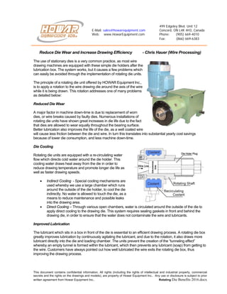
1. 499 Edgeley Blvd. Unit 12
E-Mail: sales@howarequipment.com Concord, ON L4K 4H3, Canada
Web: www.HowarEquipment.com Phone: (905) 669-4010
Fax: (866) 669-6383
This document contains confidential information. All rights (including the rights of intellectual and industrial property, commercial
secrets and the rights on the drawings and models), are property of Howar Equipment Inc.. Any use or disclosure is subject to prior
written agreement from Howar Equipment Inc.. Rotating Die Benefits 2016.docx
Reduce Die Wear and Increase Drawing Efficiency - Chris Hauer (Wire Processing)
The use of stationary dies is a very common practice, as most wire
drawing machines are equipped with these simple die holders after the
lubrication box. The system works, but it causes a few problems which
can easily be avoided through the implementation of rotating die units.
The principle of a rotating die unit offered by HOWAR Equipment Inc.,
is to apply a rotation to the wire drawing die around the axis of the wire
while it is being drawn. This rotation addresses one of many problems
as detailed below:
Reduced Die Wear
A major factor in machine down-time is due to replacement of worn
dies, or wire breaks caused by faulty dies. Numerous installations of
rotating die units have shown great increases in die life due to the fact
that dies are allowed to wear equally throughout the bearing surface.
Better lubrication also improves the life of the die, as a well coated wire
will cause less friction between the die and wire. In turn this translates into substantial yearly cost savings
because of lower die consumption, and less machine down-time.
Die Cooling
Rotating die units are equipped with a re-circulating water
flow which directs cold water around the die holder. This
cooling water draws heat away from the die in order to
reduce drawing temperature and promote longer die life as
well as faster drawing speeds.
• Indirect Cooling - Special cooling mechanisms are
used whereby we use a large chamber which runs
around the outside of the die holder, to cool the die
indirectly. No water is allowed to touch the die, as a
means to reduce maintenance and possible leaks
into the drawing area.
• Direct Cooling – Through various open chambers, water is circulated around the outside of the die to
apply direct cooling to the drawing die. This system requires sealing gaskets in front and behind the
drawing die, in order to ensure that the water does not contaminate the wire and lubricants.
Improved Lubrication
The lubricant which sits in a box in front of the die is essential to an efficient drawing process. A rotating die box
greatly improves lubrication by continuously agitating the lubricant, and due to the rotation, it also draws more
lubricant directly into the die and loading chamber. The units prevent the creation of the “tunneling effect”
whereby an empty tunnel is formed within the lubricant, which then prevents any lubricant (soap) from getting to
the wire. Customers have always pointed out how well lubricated the wire exits the rotating die box, thus
improving the drawing process.
2. Rotating Die Units
Page 2
This document contains confidential information. All rights (including the rights of intellectual and industrial property, commercial
secrets and the rights on the drawings and models), are property of Howar Equipment Inc.. Any use or disclosure is subject to prior
written agreement from Howar Equipment Inc.. Rotating Die Benefits 2016.docx
Lubrication Boxes
The rotating die holder is only as effective as its preceding lubrication box. Most applications will use a dry soap
type lubricant, which sits in a simple box. These boxes can be simple, yet additional guides can help guide and
cradle the wire. For applications where a liquid lubricant is used, we have developed a special lubrication box
which comes complete with an inlet and outlet port for which allows the re-circulation off the liquid emulsion
lubricants. Special die boxes are also available to produce bright finished wire using 1 lubrication box which
houses 2 drawing dies.
No Die Ovalization
When drawing through a stationary die, there is always a tendency for the
wire to wear the die in 1 particular area. The rotation put on the die through
the motor driven die holder avoids this common problem. The die can be
used for longer periods (up to 500% has been documented), as it will hold
its round tolerance due to the even wear.
Increased Drawing Speed
The various benefits gained by the rotating die units amount to a decisive increase in drawing speed, as
improved lubrication, lower temperature, and even wearing dies allow the wire to travel faster without breaking.
Each application and material will yield different results, but a combination of various parameter improvements
are a sure recipe for an efficient production run.
Better Wire Finish
Through the integration of a rotating die unit in the first drawing block, wire receives a substantially better
lubricant adhesion which translates into a smoother drawing pass through the die. If lubricant is applied properly
at the beginning, it will coat the wire for the continuous drawing blocks. Less scarring is therefore possible as the
bearing surface in the dies remains smoother.
A shiny wire finish can also be accomplished through a 2 stage drawing box that creates an extremely smooth
surface which prepares the wire for any further galvanizing or plating operation.
Overall Advantages
• Longer die Life
• Improved Lubrication
• Reduced Oval Wear of Die
• Lower Drawing Temperature
• Less Wire scarring
• Custom Lubrication box Solutions
Specifications of Rotating Die Units
HOWAR Equipments’ rotating dies units are available in a large array of application specific configurations. The
units are available with fast or slow rotating mechanisms, and with many different sized and types of lubrication
boxes. Die holders are available in various sizes, mainly determined by the die casing and wire diameter and
type being drawn.
The main goal of any wire drawing operation is to produce as much good quality wire, in the shortest time
possible. While the rotating die unit may not be the only solution, it truly has proven to be a great asset to many
wire drawing facilities as retrofit equipment, as well as for wire drawing machinery manufacturers who install the
units as part of their original machines. The ease of operation, low investment cost, and great return of
investment, makes these units a smart decision for companies trying to gain that needed competitive edge.