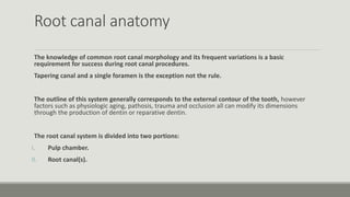
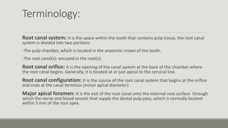
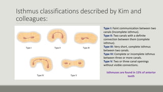
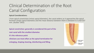
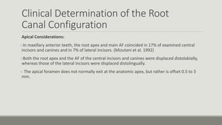
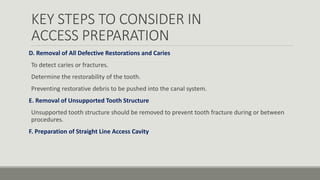
The document discusses root canal anatomy, terminology, morphology, and access cavity preparation for anterior teeth. It describes the typical root canal configuration starting at the orifice and ending at the foramen, as well as common variations. Key steps for access cavity preparation include understanding internal anatomy, evaluating the cementoenamel junction and occlusal anatomy, removing caries and defective restorations, and achieving straight-line access to locate all


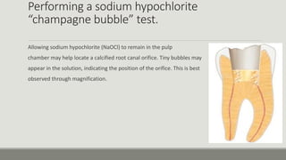


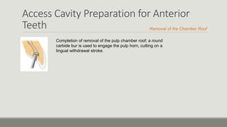
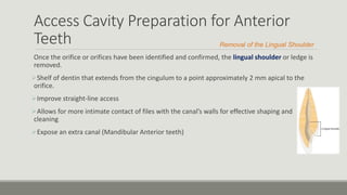
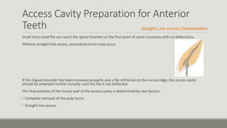


![PERI-PROSTHETIC FRACTURE NAIL-PLATE CONSTRUCT [NPC].pptx](https://cdn.slidesharecdn.com/ss_thumbnails/drarunkumardrmohamedashrafperiprostheticfrasturenail-plateconstructnpc-260209164459-7e9d15a1-thumbnail.jpg?width=640&height=640&fit=bounds)


