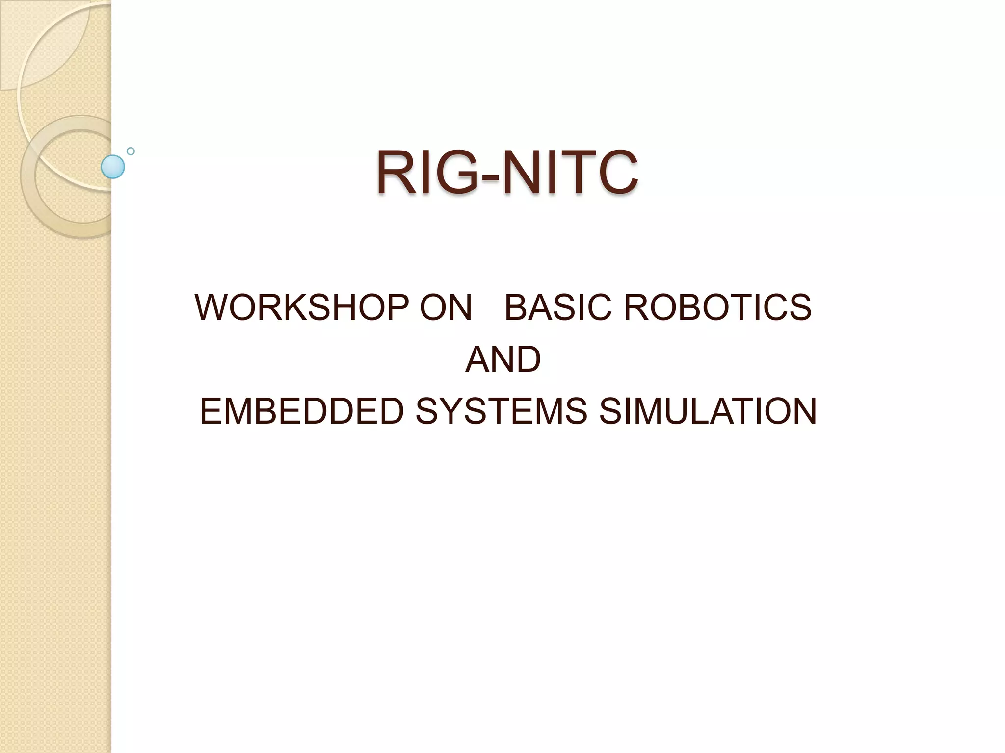
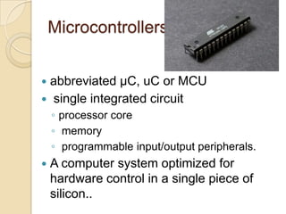
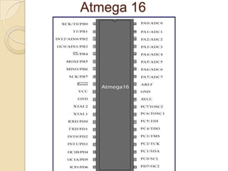
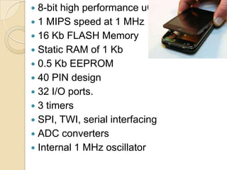
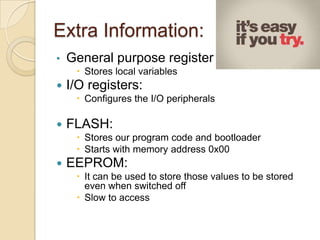
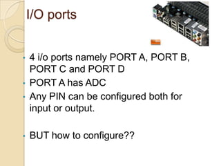
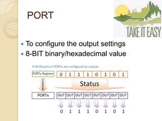
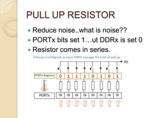
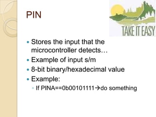
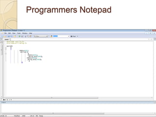
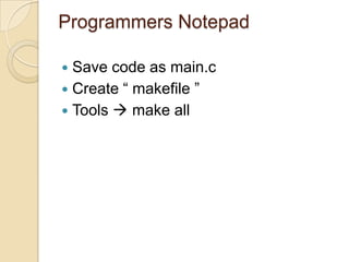
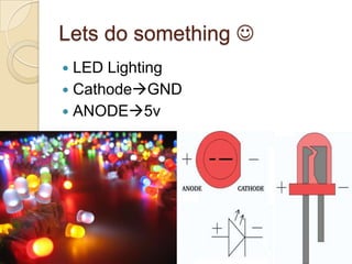
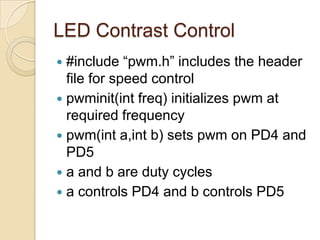
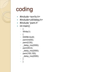
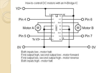
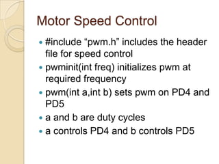
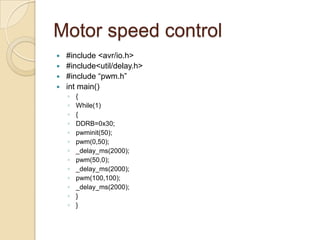
RIG-NITC
WORKSHOP ON BASIC ROBOTICS
AND
EMBEDDED SYSTEMS SIMULATION
Doubts?
 You are free to ask your doubts!!
Microcontrollers
 abbreviated µC, uC or MCU
 single integrated circuit
◦ processor core
◦ memory
◦ programmable input/output peripherals.
 A computer system optimized for
hardware control in a single piece of
silicon..
See what a uC can do.!!
Microcontrollers
 Most popular microcontrollers.
◦ AVR
◦ ARM
◦ PIC
◦ 8051
E.g. AVR ATmega8,ATmega16,Cortex
A8,A10
Atmega 16
 8-bit high performance uC
 1 MIPS speed at 1 MHz
 16 Kb FLASH Memory
 Static RAM of 1 Kb
 0.5 Kb EEPROM
 40 PIN design
 32 I/O ports.
 3 timers
 SPI, TWI, serial interfacing
 ADC converters
 Internal 1 MHz oscillator
Extra Information:
• General purpose register :
 Stores local variables
 I/O registers:
 Configures the I/O peripherals
 FLASH:
 Stores our program code and bootloader
 Starts with memory address 0x00
 EEPROM:
 It can be used to store those values to be stored
even when switched off
 Slow to access
I/O ports
• 4 i/o ports namely PORT A, PORT B,
PORT C and PORT D
• PORT A has ADC
• Any PIN can be configured both for
input or output.
• BUT how to configure??
AVR REGISTERS
 Stores some important values
 Windows registry..?
 Contains address of pins in
hexadecimal values
 Stores the configuration settings
Registers 
 Data Direction Register(DDR)
◦ 0 means INPUT PIN
◦ 1 means OUTPUT PIN
 PORT Register
◦ Configures output
 0 means 0v
 1 means 5v
 PIN register
◦ Stores the input at any PIN
 1if input is a 5v signal
 0 if input is 0v
Binary to HexaDecimal
Conversion
 Easy to express.
 Binary contains 0 and 1
 Hexadecimal s/m contain 0 to 9 and A
to F
 Binary to hex
 Hex to binary
Use of TTL logic.?
 What is TTL logic
 0’s and 1’s  what is its meaning??
 0GND….but what is GND
 1VCC…what is VCC
DDR
 DDRx where x=A,B,C,D
 8-BIT binary/hexadecimal value
 Example:
◦ DDRA=0B01110101;
PORT
 To configure the output settings
 8-BIT binary/hexadecimal value
PULL UP RESISTOR
 Reduce noise..what is noise??
 PORTx bits set 1…ut DDRx is set 0
 Resistor comes in series.
Input monitoring??
 Have you ever thought.?
 How?
PIN
 Stores the input that the
microcontroller detects…
 Example of input s/m
 8-bit binary/hexadecimal value
 Example:
◦ If PINA==0b00101111do something
But how to write the code??
Embedded C
• Most powerful programming Language
• Fast execution
• Reduced Instructions
• Similar to simple C coding
Essential Software and
Hardware
 Softwares:(will be provided: open source)
◦ Winavr
◦ HIDbootFlash
◦ Proteus ISIS
 Hardwares:(will be provided)
◦ RigDev Board
 Low cost than corporate development boards
 Based on Atmega 16
 In built USB interfacing
Getting Started
 Install Winavr
 Install HIDbootFlash
 Check the RigDev Board
◦ Programmers notepad
◦ mfile
General Structure of a code
#include<avr/io.h>
int main()
{
}
This is the general format of any embedded C code that we write
for ATmega uCs.
#include<avr/io.h> includes the details about the PIN
configurations of ATmega series of uCs.
Our code is written inside the main() function.
Programmers Notepad
Programmers Notepad
 Save code as main.c
 Create “ makefile ”
 Tools  make all
Makefile
 Written in mfile
 Change mcu name
 Change frequency
Lets do something 
 LED Lighting
 CathodeGND
 ANODE5v
More about it
 Made up mostly using GaAs.
 Light emitted due to electrical
excitation
 How to identify cathode
◦ Leg method
◦ Edge method
 NEVER CONNECT LED DIRECTLY
TO SUPPLY
 Resistor in series.
Lets Do Something 
 LED Blinking
◦ #include<util/delay.h>
 _delay_ms();
 _delay_us();
 #include<avr/io.h>
#include<util/delay.h>
main()
{
DDRA=0X01;
While(1)
{
PORTA=0X01;
_delay_ms(1000);
PORTA=0X00;
_delay_ms(1000);
}
}
Pulse Width
Modulation(PWM)
 What is a PWM signal.
 DAC
Duty Cycle
How is it usefull.??
DAC examples
 LED contrast control
 RMS voltage is exploited
LED Contrast Control
 #include “pwm.h” includes the header
file for speed control
 pwminit(int freq) initializes pwm at
required frequency
 pwm(int a,int b) sets pwm on PD4 and
PD5
 a and b are duty cycles
 a controls PD4 and b controls PD5
coding
 #include <avr/io.h>
 #include<util/delay.h>
 #include “pwm.h”
 int main()
◦ {
◦ While(1)
◦ {
◦ DDRB=0x30;
◦ pwminit(50);
◦ pwm(0,50);
◦ _delay_ms(2000);
◦ pwm(50,0);
◦ _delay_ms(2000);
◦ pwm(100,100);
◦ _delay_ms(2000);
◦ }
◦ }
Motor Speed Control
 #include “pwm.h” includes the header
file for speed control
 pwminit(int freq) initializes pwm at
required frequency
 pwm(int a,int b) sets pwm on PD4 and
PD5
 a and b are duty cycles
 a controls PD4 and b controls PD5
Motor speed control
 #include <avr/io.h>
 #include<util/delay.h>
 #include “pwm.h”
 int main()
◦ {
◦ While(1)
◦ {
◦ DDRB=0x30;
◦ pwminit(50);
◦ pwm(0,50);
◦ _delay_ms(2000);
◦ pwm(50,0);
◦ _delay_ms(2000);
◦ pwm(100,100);
◦ _delay_ms(2000);
◦ }
◦ }
Have fun..!!

Rig nitc [autosaved] (copy)

  • 1.
    RIG-NITC WORKSHOP ON BASICROBOTICS AND EMBEDDED SYSTEMS SIMULATION
  • 2.
    Doubts?  You arefree to ask your doubts!!
  • 3.
    Microcontrollers  abbreviated µC,uC or MCU  single integrated circuit ◦ processor core ◦ memory ◦ programmable input/output peripherals.  A computer system optimized for hardware control in a single piece of silicon..
  • 4.
    See what auC can do.!!
  • 5.
    Microcontrollers  Most popularmicrocontrollers. ◦ AVR ◦ ARM ◦ PIC ◦ 8051 E.g. AVR ATmega8,ATmega16,Cortex A8,A10
  • 6.
  • 7.
     8-bit highperformance uC  1 MIPS speed at 1 MHz  16 Kb FLASH Memory  Static RAM of 1 Kb  0.5 Kb EEPROM  40 PIN design  32 I/O ports.  3 timers  SPI, TWI, serial interfacing  ADC converters  Internal 1 MHz oscillator
  • 8.
    Extra Information: • Generalpurpose register :  Stores local variables  I/O registers:  Configures the I/O peripherals  FLASH:  Stores our program code and bootloader  Starts with memory address 0x00  EEPROM:  It can be used to store those values to be stored even when switched off  Slow to access
  • 9.
    I/O ports • 4i/o ports namely PORT A, PORT B, PORT C and PORT D • PORT A has ADC • Any PIN can be configured both for input or output. • BUT how to configure??
  • 10.
    AVR REGISTERS  Storessome important values  Windows registry..?  Contains address of pins in hexadecimal values  Stores the configuration settings
  • 11.
    Registers   DataDirection Register(DDR) ◦ 0 means INPUT PIN ◦ 1 means OUTPUT PIN  PORT Register ◦ Configures output  0 means 0v  1 means 5v  PIN register ◦ Stores the input at any PIN  1if input is a 5v signal  0 if input is 0v
  • 12.
    Binary to HexaDecimal Conversion Easy to express.  Binary contains 0 and 1  Hexadecimal s/m contain 0 to 9 and A to F  Binary to hex  Hex to binary
  • 13.
    Use of TTLlogic.?  What is TTL logic  0’s and 1’s  what is its meaning??  0GND….but what is GND  1VCC…what is VCC
  • 14.
    DDR  DDRx wherex=A,B,C,D  8-BIT binary/hexadecimal value  Example: ◦ DDRA=0B01110101;
  • 15.
    PORT  To configurethe output settings  8-BIT binary/hexadecimal value
  • 16.
    PULL UP RESISTOR Reduce noise..what is noise??  PORTx bits set 1…ut DDRx is set 0  Resistor comes in series.
  • 17.
    Input monitoring??  Haveyou ever thought.?  How?
  • 18.
    PIN  Stores theinput that the microcontroller detects…  Example of input s/m  8-bit binary/hexadecimal value  Example: ◦ If PINA==0b00101111do something
  • 19.
    But how towrite the code??
  • 20.
    Embedded C • Mostpowerful programming Language • Fast execution • Reduced Instructions • Similar to simple C coding
  • 21.
    Essential Software and Hardware Softwares:(will be provided: open source) ◦ Winavr ◦ HIDbootFlash ◦ Proteus ISIS  Hardwares:(will be provided) ◦ RigDev Board  Low cost than corporate development boards  Based on Atmega 16  In built USB interfacing
  • 22.
    Getting Started  InstallWinavr  Install HIDbootFlash  Check the RigDev Board ◦ Programmers notepad ◦ mfile
  • 23.
    General Structure ofa code #include<avr/io.h> int main() { } This is the general format of any embedded C code that we write for ATmega uCs. #include<avr/io.h> includes the details about the PIN configurations of ATmega series of uCs. Our code is written inside the main() function.
  • 24.
  • 25.
    Programmers Notepad  Savecode as main.c  Create “ makefile ”  Tools  make all
  • 26.
    Makefile  Written inmfile  Change mcu name  Change frequency
  • 27.
    Lets do something  LED Lighting  CathodeGND  ANODE5v
  • 28.
    More about it Made up mostly using GaAs.  Light emitted due to electrical excitation  How to identify cathode ◦ Leg method ◦ Edge method  NEVER CONNECT LED DIRECTLY TO SUPPLY  Resistor in series.
  • 29.
    Lets Do Something  LED Blinking ◦ #include<util/delay.h>  _delay_ms();  _delay_us();  #include<avr/io.h> #include<util/delay.h> main() { DDRA=0X01; While(1) { PORTA=0X01; _delay_ms(1000); PORTA=0X00; _delay_ms(1000); } }
  • 30.
    Pulse Width Modulation(PWM)  Whatis a PWM signal.  DAC
  • 31.
    Duty Cycle How isit usefull.??
  • 32.
    DAC examples  LEDcontrast control  RMS voltage is exploited
  • 33.
    LED Contrast Control #include “pwm.h” includes the header file for speed control  pwminit(int freq) initializes pwm at required frequency  pwm(int a,int b) sets pwm on PD4 and PD5  a and b are duty cycles  a controls PD4 and b controls PD5
  • 34.
    coding  #include <avr/io.h> #include<util/delay.h>  #include “pwm.h”  int main() ◦ { ◦ While(1) ◦ { ◦ DDRB=0x30; ◦ pwminit(50); ◦ pwm(0,50); ◦ _delay_ms(2000); ◦ pwm(50,0); ◦ _delay_ms(2000); ◦ pwm(100,100); ◦ _delay_ms(2000); ◦ } ◦ }
  • 36.
    Motor Speed Control #include “pwm.h” includes the header file for speed control  pwminit(int freq) initializes pwm at required frequency  pwm(int a,int b) sets pwm on PD4 and PD5  a and b are duty cycles  a controls PD4 and b controls PD5
  • 37.
    Motor speed control #include <avr/io.h>  #include<util/delay.h>  #include “pwm.h”  int main() ◦ { ◦ While(1) ◦ { ◦ DDRB=0x30; ◦ pwminit(50); ◦ pwm(0,50); ◦ _delay_ms(2000); ◦ pwm(50,0); ◦ _delay_ms(2000); ◦ pwm(100,100); ◦ _delay_ms(2000); ◦ } ◦ }
  • 38.