The document discusses a density-based traffic light control system using Raspberry Pi and image processing to address urban traffic congestion. It proposes a solution that dynamically adjusts traffic signals based on vehicle density, allowing emergency vehicles to pass more efficiently. The system utilizes hardware components like cameras, IR sensors, and RF transmitters to automate traffic management and improve road safety.

![International Journal of Trend in Scientific Research and Development (IJTSRD) @ www.ijtsrd.com eISSN: 2456-6470
@ IJTSRD | Unique Paper ID - IJTSRD23293 | Volume – 3 | Issue – 3 | Mar-Apr 2019 Page: 1285
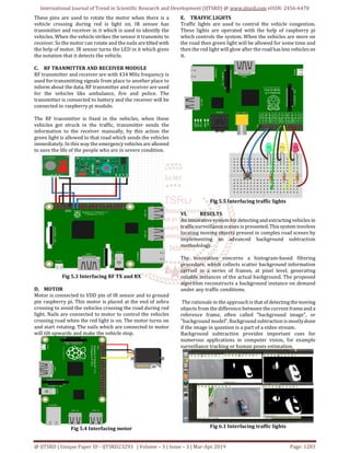
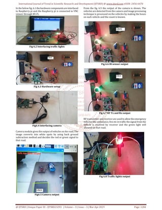
Fig 6.9 Entire output
CONCLUSION
In accordance with the traffic congestion in urban areas, we
designed a density based traffic control system by using
Raspberry pi, IR sensor, Camera module, Image processing.
The camera module is installed at the starting of the road.
This gives the count of vehicles on the road, with the help of
that count we can control the traffic by allowing the vehicles
where the density is more. The system provides better
flexibility to manage the traffic. The information about the
ambulance is also known by transmitting the signal and will
be displayed green light on the road.
When the vehicle tries to cross the road during red light, it
will get damaged by the nails connected to motor. Density
based traffic light controlsystemisproductiveand it reduces
the traffic in urban areas, time consumption due to heavy
traffic.
REFERENCES
[1] 2015 International Conference on Computers,
Communications, and Systems by Y M Jagadeesh ; G.
Merlin Suba ; S Karthik ; K Yokesh
[2] 2015 International Conference on Electrical
Engineering and Information Communication
Technology (ICEEICT) by Mohammad Shahab Uddin ;
Ayon Kumar Das ; Md. Abu Taleb
[3] 2016 Third International Conference on Electrical,
Electronics, Computer Engineering and their
Applications (EECEA) byBilal Ghazal ; KhaledElKhatib
; Khaled Chahine ; Mohamad Kherfan
[4] 2017 International Conference on Inventive
Computing and Informatics (ICICI)2017byR.Bhargavi
Devi ; D. Kavya Reddy ; E. Sravani ; Gaddam Srujan ;
Shiv Shankar ; Shubhro Chakrabartty
[5] 2017 1st International Conference on Intelligent
Systems and Information Management (ICISIM)
Year:2017 Authors: Swapnil Manohar Shinde
[6] 2017 International Conference on Energy,
Communication, Data Analytics and Soft Computing
(ICECDS);Conference: 1-2 Aug. 2017 Date Added to
IEEE Xplore: 21 June 2018 Authors: Elizabeth
Basil,Prof.S.D.Sawant
[7] 2017 3rd International Conference on Electrical
Information and Communication Technology (EICT)
byTaqi Tahmid ; Eklas Hossain
[8] https://www.researchgate.net/publication/32327953
1_An_IoT_based_Intelligent_Traffic_Congestion_Control
_System_for_Road_Crossings by Pampa Sadhukhan,
Firoj Gazi
[9] https://www.researchgate.net/publication/30121453
6_IoT_Based_Dynamic_Road_Traffic_Management_for_S
mart_Cities [accessed Sep 11 2018].
[10] https://www.ijecs.in/index.php/ijecs/article/view/24
76 Online Traffic Light Control System G. Karthika S.
Prabhu Ram, ArticleDatePublished:15February2017
[11] https://www.ripublication.com/ijaer17/ijaerv12n19_
37.pdf Ashok.P.V B.Tech Graduate, Department of
Information Technology, SRM University,
Kattankaluthur Campus, Chennai-603203, India.
[12] http://www.ijareeie.com/upload/2018/january/14_IO
T.pdf by Dr.Sanjeev Sharma, Vaishnavi Giradkar ,Aarti
Sanap,Snehal Sarolka
[13] http://thesai.org/Downloads/Volume6No2/Paper6Int
elligent_Traffic_Information_System_Based.pdf -Hasan
Omar Al-Sakran](https://image.slidesharecdn.com/276densitybasedtrafficlightcontrolsystemusingraspberrypi-190619120359/85/Density-Based-Traffic-Lightcontrol-System-using-Raspberry-Pi-5-320.jpg)