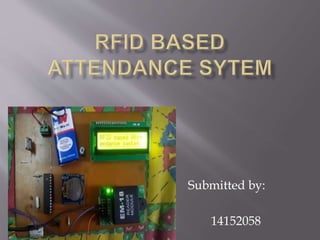
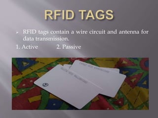
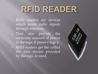
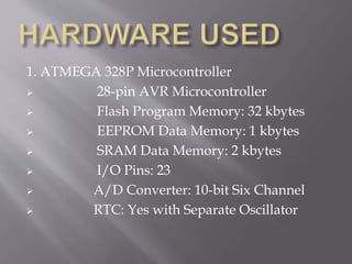
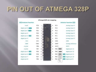
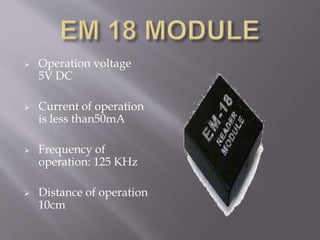
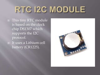
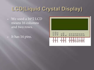
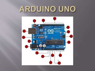
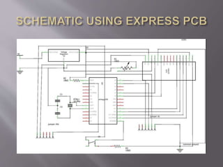
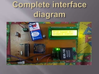
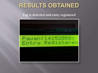
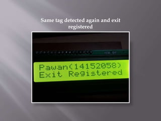
Submitted by:
14152058
Introduction
1.What is a RFID system?
Hardware requirements
1. ATMEGA 328p Microcontroller
2. EM-18 Module (RFID Reader)
3. Passive tags
4. RTC (Real Time Clock)
5. PCB
6. LCD(16*2)
List of software and tools used
1. ARDUINO IDE
2. EXPRESS PCB
3. ARDUINO UNO
 RFID stands for Radio Frequency Identification.
 RFID is a technology which wirelessly identifies the
chip or tag of interest and captures the data.
 It is a member of AIDC(Automatic Identification and
Data) technologies.
 RFID system comprises of
1. RFID tags
2. RFID reader
3. RFID middleware.
 RFID tags contain a wire circuit and antenna for
data transmission.
1. Active 2. Passive
 RFID readers are devices
which emits radio signals
through antennae.
 They also provide the
necessary amount of power
to the tags, if passive tags a
 RFID readers get the collect
the data stream provided
by the tags. re used.
 It collects all the data that tags give, does the
filtering task.
 RFID middleware actually is used to control
and manage the RFID readers’ infrastructures.
 It is considered as the brain of any
 RFID system as it provides the most important
functionalities.
 Some of its key functionalities are efficient
management of data created by the RFID
system.
1. ATMEGA 328P Microcontroller
 28-pin AVR Microcontroller
 Flash Program Memory: 32 kbytes
 EEPROM Data Memory: 1 kbytes
 SRAM Data Memory: 2 kbytes
 I/O Pins: 23
 A/D Converter: 10-bit Six Channel
 RTC: Yes with Separate Oscillator
 Operation voltage
5V DC
 Current of operation
is less than50mA
 Frequency of
operation: 125 KHz
 Distance of operation
10cm
 This tiny RTC module
is based on the clock
chip DS1307 which
supports the I2C
protocol.
 It uses a Lithium cell
battery (CR1225).
 We used a 16*2 LCD
means 16 columns
and two rows.
 It has 14 pins.
Tag is detected and entry registered
Same tag detected again and exit
registered
Rfid based attendance sytem

Rfid based attendance sytem

  • 1.
  • 2.
    Introduction 1.What is aRFID system? Hardware requirements 1. ATMEGA 328p Microcontroller 2. EM-18 Module (RFID Reader) 3. Passive tags 4. RTC (Real Time Clock) 5. PCB 6. LCD(16*2)
  • 3.
    List of softwareand tools used 1. ARDUINO IDE 2. EXPRESS PCB 3. ARDUINO UNO
  • 4.
     RFID standsfor Radio Frequency Identification.  RFID is a technology which wirelessly identifies the chip or tag of interest and captures the data.  It is a member of AIDC(Automatic Identification and Data) technologies.  RFID system comprises of 1. RFID tags 2. RFID reader 3. RFID middleware.
  • 5.
     RFID tagscontain a wire circuit and antenna for data transmission. 1. Active 2. Passive
  • 6.
     RFID readersare devices which emits radio signals through antennae.  They also provide the necessary amount of power to the tags, if passive tags a  RFID readers get the collect the data stream provided by the tags. re used.
  • 7.
     It collectsall the data that tags give, does the filtering task.  RFID middleware actually is used to control and manage the RFID readers’ infrastructures.  It is considered as the brain of any  RFID system as it provides the most important functionalities.  Some of its key functionalities are efficient management of data created by the RFID system.
  • 8.
    1. ATMEGA 328PMicrocontroller  28-pin AVR Microcontroller  Flash Program Memory: 32 kbytes  EEPROM Data Memory: 1 kbytes  SRAM Data Memory: 2 kbytes  I/O Pins: 23  A/D Converter: 10-bit Six Channel  RTC: Yes with Separate Oscillator
  • 10.
     Operation voltage 5VDC  Current of operation is less than50mA  Frequency of operation: 125 KHz  Distance of operation 10cm
  • 11.
     This tinyRTC module is based on the clock chip DS1307 which supports the I2C protocol.  It uses a Lithium cell battery (CR1225).
  • 12.
     We useda 16*2 LCD means 16 columns and two rows.  It has 14 pins.
  • 16.
    Tag is detectedand entry registered
  • 17.
    Same tag detectedagain and exit registered