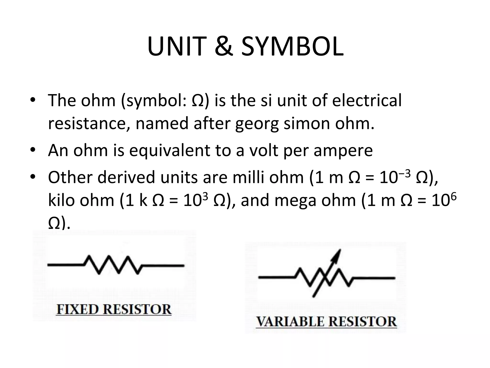
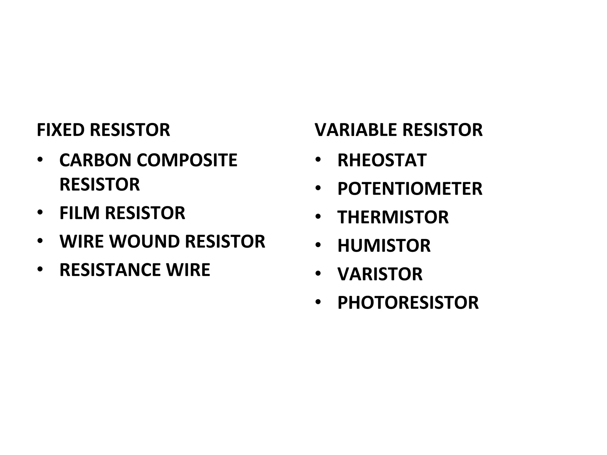
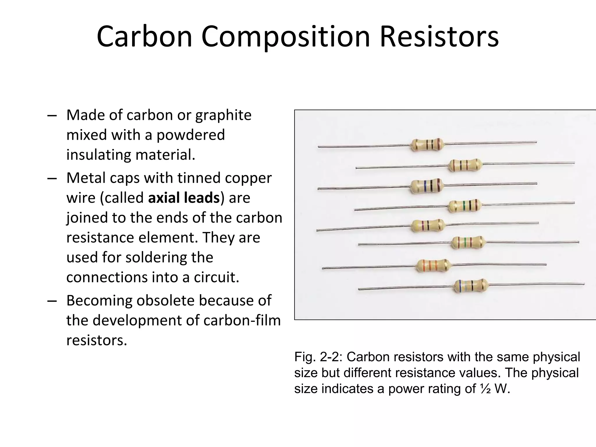
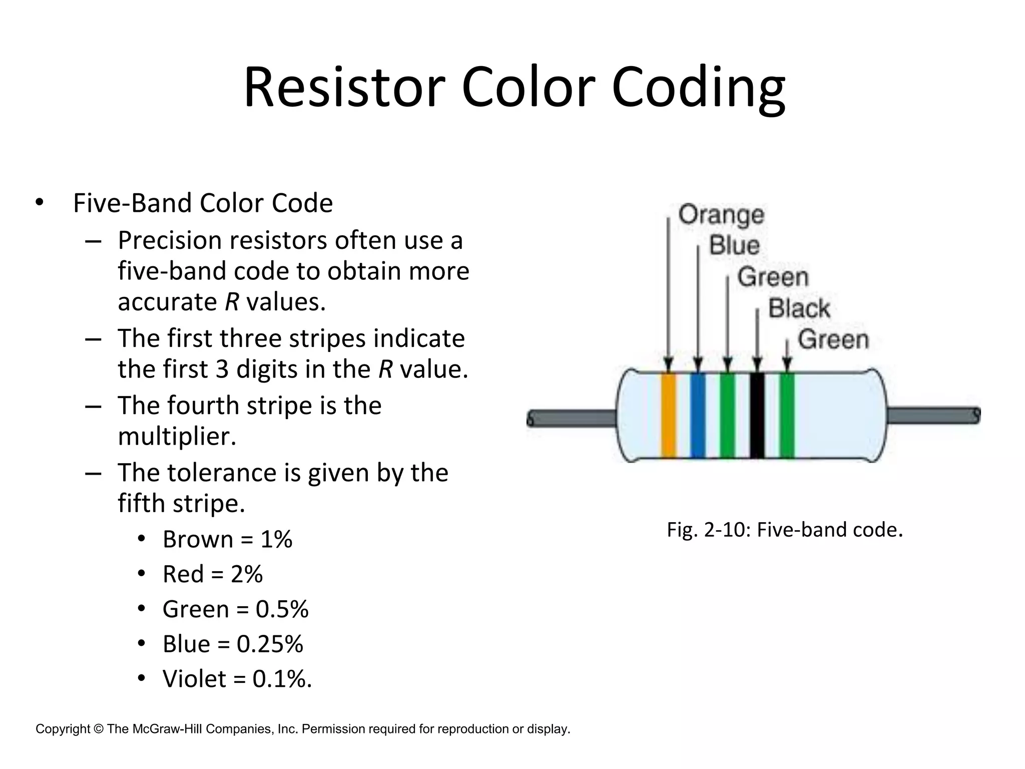
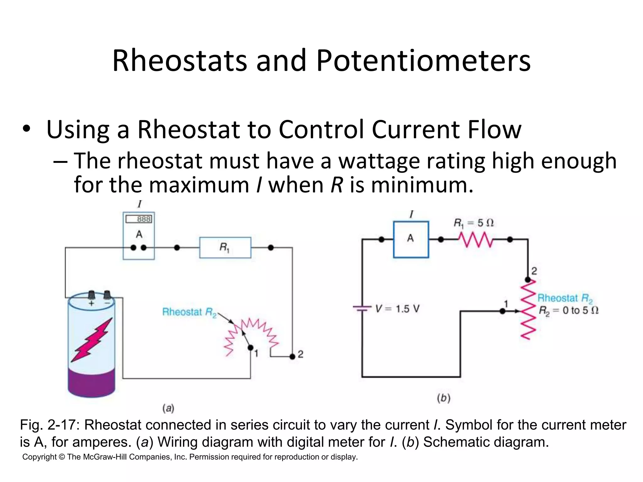
SlideShare a Scribd company logo
EST130 BASIC ELECTRICAL &
ELECTRONICS
• MODULE IV
– Introduction to Semiconductor devices
• MODULE V
– Basic electronic circuits and instrumentation
• MODULE VI
– Introduction to Communication Systems
RESISTOR
WHAT IS A RESISTOR?
• Resistor is a passive two -terminal electrical
component that implements electrical resistance as
a circuit element.
• The ratio of the voltage applied across a resistor's
terminals to the intensity of current through the
circuit is called resistance.
• This relation is represented by ohm's law:
V = I R
UNIT & SYMBOL
• The ohm (symbol: Ω) is the si unit of electrical
resistance, named after georg simon ohm.
• An ohm is equivalent to a volt per ampere
• Other derived units are milli ohm (1 m Ω = 10−3 Ω),
kilo ohm (1 k Ω = 103 Ω), and mega ohm (1 m Ω = 106
Ω).
TYPES OF RESISTORS
FIXED RESISTOR
• CARBON COMPOSITE
RESISTOR
• FILM RESISTOR
• WIRE WOUND RESISTOR
• RESISTANCE WIRE
VARIABLE RESISTOR
• RHEOSTAT
• POTENTIOMETER
• THERMISTOR
• HUMISTOR
• VARISTOR
• PHOTORESISTOR
Wire Wound Resistor
– Special resistance wire is
wrapped around an insulating
core, typically porcelain,
cement, or pressed paper.
– These resistors are typically
used for high-current
applications with low
resistance and appreciable
power
Fig. : Large wire-wound resistors with 50-W power ratings.
(a) Fixed R, length of 5 in. (b) Variable R, diameter of 3 in.
Carbon Composition Resistors
– Made of carbon or graphite
mixed with a powdered
insulating material.
– Metal caps with tinned copper
wire (called axial leads) are
joined to the ends of the carbon
resistance element. They are
used for soldering the
connections into a circuit.
– Becoming obsolete because of
the development of carbon-film
resistors.
Fig. 2-2: Carbon resistors with the same physical
size but different resistance values. The physical
size indicates a power rating of ½ W.
Carbon Film Resistors
– Carbon film resistor is a fixed
resistor that uses a carbon
film that is deposited on a
ceramic former, to restrict
the flow of current
– Compared to carbon
composition resistors, carbon-
film resistors have tighter
tolerances, are less sensitive
to temperature changes and
aging, and generate less
noise.
Metal Film Resistor
• In contrast to carbon film resistors, metal
oxide film resistors use thin metal oxide
films to coat an insulating ceramic rod.
• The compound made out of oxygen
atoms and other atoms works wonders in
forming a coating film.
• However, metal oxide film resistors are
made using tin oxide. Also, antimony
oxide is added to yield better resistance.
• Metal film resistors have very tight
tolerances, are less sensitive to
temperature changes and aging, and
generate less noise.
Fig. 2-5: Construction of a metal film
resistor.
Surface-Mount Resistors (also called
chip resistors)
– These resistors are:
• Temperature-stable and rugged
• Their end electrodes are soldered
directly to a circuit board.
• Much smaller than conventional
resistors with axial leads.
• Power dissipation rating is usually
1/8 to ¼ W
Fig. 2-6: Typical chip
resistors.
Fusible Resistors
– Fusible resistors are wire-wound resistors made
to burn open easily when the power rating is
exceeded. They serve a dual function as both a
fuse and a resistor.
Thermistors
– Thermistors are temperature-
sensitive resistors whose
resistance value changes with
changes in operating temperature.
– Used in electronic circuits where
temperature measurement,
control, and compensation are
desired.
Fig. : Typical thermistor shapes and sizes.
Resistor Color Coding
– Carbon resistors are small, so their R value in
ohms is marked using a color-coding system.
– Colors represent numerical values.
– Coding is standardized by the Electronic Industries
Alliance (EIA).
Resistor Color Coding
• Resistor Color Code
0 Black
1 Brown
2 Red
3 Orange
4 Yellow
5 Green
6 Blue
7 Violet
8 Gray
9 White
Color Code
Fig.: How to read color stripes on carbon
resistors for R in ohms.
Resistor Color Coding
• Resistors under 10 Ω:
– The multiplier band is either gold or silver.
• For gold, multiply by 0.1.
• For silver, multiply by 0.01.
Fig.: Examples of color-coded R values, with percent tolerance.
Resistor Color Coding
• Applying the Color
Code
– The amount by
which the actual R
can differ from the
color-coded value
is its tolerance.
Tolerance is
usually stated in
percentages.
Yellow = 4
Resistor Color Coding
• What is the nominal value and permissible
ohmic range for each resistor shown?
1 kΩ (950 to 1050 Ω)
390 Ω (370.5 to 409.5 Ω)
22 kΩ (20.9 to 23.1 kΩ)
1 MΩ (950 kΩ to 1.05 MΩ)
Resistor Color Coding
• Five-Band Color Code
– Precision resistors often use a
five-band code to obtain more
accurate R values.
– The first three stripes indicate
the first 3 digits in the R value.
– The fourth stripe is the
multiplier.
– The tolerance is given by the
fifth stripe.
• Brown = 1%
• Red = 2%
• Green = 0.5%
• Blue = 0.25%
• Violet = 0.1%.
Fig. 2-10: Five-band code.
Copyright © The McGraw-Hill Companies, Inc. Permission required for reproduction or display.
Problem 2-6
• Using the five-band code, indicate the colors
of the bands for each of the following
resistors:
a) 110 Ω ± 1%
b) 34 kΩ ± 0.5%
c) 82.5 kΩ ± 2% Tolerance
Brown = 1%
Red = 2%
Green = 0.5%
Blue = 0.25%
Violet = 0.1%.
0 Black
1 Brown
2 Red
3 Orange
4 Yellow
5 Green
6 Blue
7 Violet
8 Gray
9 White
Color Code
Resistor Color Coding
• Zero-Ohm Resistor
– Has zero ohms of
resistance.
– Used for connecting two
points on a printed-circuit
board.
– Body has a single black
band around it.
– Wattage ratings are
typically 1/8- or 1/4-watt.
Fig. 2-11: A zero-ohm resistor is
indicated by a single black color band
around the body of the resistor.
Copyright © The McGraw-Hill Companies, Inc. Permission required for reproduction or display.
Chip Resistor Coding System
• Body color is usually white or off-white
• End terminals are C-shaped
• Three (four) digits on the body or on the film
• First 2 (3) digits indicate the first two (three) numbers
• Third (fourth) digit indicates the multiplier
• Are available in tolerances of ±1% ±5% but tolerances
are not indicated on the chip
• The letter R is used to signify a decimal point for values
between 1 to 10 ohms (1R5 means 1.5 ohms)
Variable Resistors
– A variable resistor is a resistor whose resistance
value can be changed.
Copyright © The McGraw-Hill Companies, Inc. Permission required for reproduction or display.
Variable resistors
• Decade resistance box
– Provides any R within a wide range of values
– First dial is the units or R × 1 dial.
– Second dial is the tens or R × 10 dial
– The hundreds or R × 100 dial has an R of 0 to
900Ω
– Etc.
– Dials are connected internally so that their
values add to one another.
Problem
• Indicate the total resistance of a decade
resistor whose dial settings are as follows:
– R × 100 k is set to 6
– R × 10 k is set to 8
– R × 1 k is set to 0
– R × 100 is set to 2
– R × 10 is set to 8
– R × 1 is set to 0
Rheostats and Potentiometers
• Rheostats and potentiometers are variable resistances used to
vary the amount of current or voltage in a circuit.
– Rheostats:
• Two terminals.
• Connected in series with the load and the voltage source.
• Varies the current.
Copyright © The McGraw-Hill Companies, Inc. Permission required for reproduction or display.
Rheostats and Potentiometers
– Potentiometers:
• Three terminals.
• Ends connected across the voltage source.
• Third variable arm taps off part of the voltage.
Copyright © The McGraw-Hill Companies, Inc. Permission required for reproduction or display.
Rheostats and Potentiometers
Copyright © The McGraw-Hill Companies, Inc. Permission required for reproduction or display.
Rheostats and Potentiometers
• Using a Rheostat to Control Current Flow
– The rheostat must have a wattage rating high enough
for the maximum I when R is minimum.
Fig. 2-17: Rheostat connected in series circuit to vary the current I. Symbol for the current meter
is A, for amperes. (a) Wiring diagram with digital meter for I. (b) Schematic diagram.
Copyright © The McGraw-Hill Companies, Inc. Permission required for reproduction or display.
Rheostats and Potentiometers
• Potentiometers
– Potentiometers are three-
terminal devices.
– The applied V is input to the
two end terminals of the
potentiometer.
– The variable V is output
between the variable arm
and an end terminal.
Fig. 2-18: Potentiometer connected across voltage
source to function as a voltage divider. (a) Wiring
diagram. (b) Schematic diagram.
Copyright © The McGraw-Hill Companies, Inc. Permission required for reproduction or display.
Problem 2-8
• Show two different ways to wire a
potentiometer so that it will work as a
rheostat.
Potentiometer Used as a Rheostat
• A potentiometer may be used
as a rheostat by simply using
the wiper terminal and one of
the other terminals, the third
terminal is left unconnected
and unused
• Another method is to wire
the unused terminal to the
center terminal
Power Rating of Resistors
– In addition to having the required ohms value, a
resistor should have a wattage rating high enough to
dissipate the power produced by the current without
becoming too hot.
– Power rating depends on the resistor’s construction.
– A larger physical size indicates a higher power rating.
– Higher-wattage resistors can operate at higher
temperatures.
– Wire-wound resistors are physically larger and have
higher power ratings than carbon resistors.
Good to Know
• Maximum allowable current for any resistance setting is
calculated as:
P and R are the rated value of rheostat
Q. What is Imax of a 5-KΩ 2-W rheostat?
▪ Maximum voltage which produces the rated power dissipation
can be calculated as:
Resistor Troubles
– Resistors can become open or they can drift out of
tolerance.
– Some controls (especially volume and tone controls)
may become noisy or scratchy-sounding, indicating a
dirty or worn-out resistance element.
– Due to the very nature of their construction, resistors
can short out internally. They may, however, become
short-circuited by another component in the circuit.
An open resistor measures infinite resistance.
An example of an out-of-tolerance resistor:
Resistor Troubles
1 kΩ,5%
nominal
1.5 kΩ
∞ Ω
Resistor Troubles
– Resistance measurements are made with an
ohmmeter.
– The ohmmeter has its own voltage source, so
voltage must be off in the circuit being tested.
Otherwise the ohmmeter may become damaged.
Resistor Troubles
– All experienced technicians have seen a burnt
resistor.
– This is usually caused by a short somewhere else
in the circuit which causes a high current to flow
in the resistor.
– When a resistor’s power rating is exceeded, it can
burn open or drift way out of tolerance.
Critical Thinking Problem
• A manufacturer of carbon-film resistors
specifies a maximum working voltage of 250V
for all its ¼-W resistors. Exceeding 250 V
causes internal arcing within the resistor.
Above what minimum resistance will the
maximum working voltage be exceeded
before its ¼-W power dissipation is
exceeded?
Capacitors
• Capacitors are one of the fundamental passive components. In its most basic
form, it is composed of two plates separated by a dielectric.
• Examples of dielectric media are glass, air, paper, vaccum etc.
• The ability to store charge is the definition of capacitance.
Conductors
The Capacitor
Initially uncharged
Charging
Fully charged
Source removed
The charging
process…
Capacitance is the ratio of charge to voltage
Rearranging, the amount of charge on a capacitor is
determined by the size of the capacitor (C) and the voltage
(V).
If a 22 μF capacitor is connected to a 10 V
source, the charge is 220 μC
Capacitance
A capacitor stores energy in the form of an electric field that is established
by the opposite charges on the two plates. The energy of a charged
capacitor is given by the equation
Capacitance
where
W = the energy in joules
C = the capacitance in farads
V = the voltage in volts
The capacitance of a capacitor depends on three physical
characteristics.
C is directly proportional to
and the plate area.
the relative dielectric constant
C is inversely proportional to
the distance between the plates
Capacitance
Find the capacitance of a 4.0 cm diameter sensor
immersed in oil if the plates are separated by 0.25 mm.
The plate area is
The distance between the plates is
178 pF
Specifications of a Capacitor
• Voltage rating(Working Voltage)
• Tolerance
• Power factor
• Dielectric absorption
• Leakage resistance
Classification of Capacitors
Fixed Capacitors
• Electrostatic Capacitors
– Paper Capacitor
– Mica Capacitor
– Ceramic Capacitor
– Polyester Capacitor
• Electrolytic Capacitors
– Aluminium
– Tantalum
Variable Capacitors
• Gang Capacitor
• Trimmer Capacitor
• Padder Capacitor
Electrolytic Capacitor
• An electrolyte is used as a medium to produce high dielectric constant .
• Utilizes the electro-chemical process electrolysis.
• Preferred in situations where high capacitance value in the order of 1000micro
farad is required.
• Two types of electrolytic capacitors are in common use
– Aluminium electrolytic capacitor
– Tantalum electrolytic capacitor
• The main advantage of tantalum electrolytic capacitors over aluminium
electrolytic capacitors is that they are more stable, lighter and smaller. These are
costlier than aluminium electrolytes.
• Tantalum capacitors are superior to aluminium because of its lower leakage
resistance, longer life, and higher stability in operation, higher reliability and
smaller in size than other types.
EST130 BASIC ELECTRICAL & ELECTRONICS.pptx

More Related Content

Similar to EST130 BASIC ELECTRICAL & ELECTRONICS.pptx

RESISTANCE.pptx
RESISTANCE.pptxRESISTANCE.pptx
RESISTANCE.pptx
CarlLouiseCapute
 
Intro to Electricity.pdf
Intro to Electricity.pdfIntro to Electricity.pdf
Intro to Electricity.pdf
DavidKimunyan
 
Basic Electronics
Basic ElectronicsBasic Electronics
Basic Electronics
Pitambar Behera
 
1.Resistors_new NOTE.pdf
1.Resistors_new NOTE.pdf1.Resistors_new NOTE.pdf
1.Resistors_new NOTE.pdf
anushafi1
 
Intro to Electricity.ppt
Intro to Electricity.pptIntro to Electricity.ppt
Intro to Electricity.ppt
johnjacobcabal
 
Conductor pert. 4
Conductor pert. 4Conductor pert. 4
Conductor pert. 4
Novia Putri
 
CH5 electric components.pptx
CH5 electric components.pptxCH5 electric components.pptx
CH5 electric components.pptx
meleseteshome1
 
Electronics and Communication Engineering
Electronics and Communication EngineeringElectronics and Communication Engineering
Electronics and Communication Engineering
Ekeeda
 
Introduction to Electricity
Introduction to Electricity Introduction to Electricity
Introduction to Electricity
johny renoald
 
Electrical Engineering
Electrical EngineeringElectrical Engineering
Electrical Engineering
Ekeeda
 
4.3.c form 4 circuit components
4.3.c form 4 circuit components4.3.c form 4 circuit components
4.3.c form 4 circuit components
chris lembalemba
 
Lab 02 Resistor color coding and ohms law
Lab 02   Resistor color coding and ohms lawLab 02   Resistor color coding and ohms law
Lab 02 Resistor color coding and ohms lawHassaan Rahman
 
Electronic passive components
Electronic passive componentsElectronic passive components
Electronic passive components
shalet kochumuttath Shaji
 
Resistor
ResistorResistor
Resistor
Aparna1205
 
Basic Electrical Parameters ( Basic Electrical Engineering)
Basic Electrical Parameters ( Basic Electrical Engineering)Basic Electrical Parameters ( Basic Electrical Engineering)
Basic Electrical Parameters ( Basic Electrical Engineering)
Chetan Patil
 
Resistor-Basics knowledge knowing parallel and series.pptx
Resistor-Basics knowledge knowing parallel and series.pptxResistor-Basics knowledge knowing parallel and series.pptx
Resistor-Basics knowledge knowing parallel and series.pptx
RobertCarreonBula
 
resistor
resistorresistor
resistor
JANE MALOLES
 
Lecture 02 Resistance.pdf
Lecture 02 Resistance.pdfLecture 02 Resistance.pdf
Lecture 02 Resistance.pdf
OnofreAlgaraJr2
 
Resistors: Types and Uses
Resistors: Types and UsesResistors: Types and Uses
Resistors: Types and Uses
Jessa Arnado
 

Similar to EST130 BASIC ELECTRICAL & ELECTRONICS.pptx (20)

RESISTANCE.pptx
RESISTANCE.pptxRESISTANCE.pptx
RESISTANCE.pptx
 
Intro to Electricity.pdf
Intro to Electricity.pdfIntro to Electricity.pdf
Intro to Electricity.pdf
 
Basic Electronics
Basic ElectronicsBasic Electronics
Basic Electronics
 
1.Resistors_new NOTE.pdf
1.Resistors_new NOTE.pdf1.Resistors_new NOTE.pdf
1.Resistors_new NOTE.pdf
 
Intro to Electricity.ppt
Intro to Electricity.pptIntro to Electricity.ppt
Intro to Electricity.ppt
 
Conductor pert. 4
Conductor pert. 4Conductor pert. 4
Conductor pert. 4
 
CH5 electric components.pptx
CH5 electric components.pptxCH5 electric components.pptx
CH5 electric components.pptx
 
Electronics and Communication Engineering
Electronics and Communication EngineeringElectronics and Communication Engineering
Electronics and Communication Engineering
 
Introduction to Electricity
Introduction to Electricity Introduction to Electricity
Introduction to Electricity
 
Electrical Engineering
Electrical EngineeringElectrical Engineering
Electrical Engineering
 
4.3.c form 4 circuit components
4.3.c form 4 circuit components4.3.c form 4 circuit components
4.3.c form 4 circuit components
 
Lab 02 Resistor color coding and ohms law
Lab 02   Resistor color coding and ohms lawLab 02   Resistor color coding and ohms law
Lab 02 Resistor color coding and ohms law
 
Electronic passive components
Electronic passive componentsElectronic passive components
Electronic passive components
 
Resistor
ResistorResistor
Resistor
 
Basic Electrical Parameters ( Basic Electrical Engineering)
Basic Electrical Parameters ( Basic Electrical Engineering)Basic Electrical Parameters ( Basic Electrical Engineering)
Basic Electrical Parameters ( Basic Electrical Engineering)
 
Resistor-Basics knowledge knowing parallel and series.pptx
Resistor-Basics knowledge knowing parallel and series.pptxResistor-Basics knowledge knowing parallel and series.pptx
Resistor-Basics knowledge knowing parallel and series.pptx
 
1. Resistors .pptx
1. Resistors .pptx1. Resistors .pptx
1. Resistors .pptx
 
resistor
resistorresistor
resistor
 
Lecture 02 Resistance.pdf
Lecture 02 Resistance.pdfLecture 02 Resistance.pdf
Lecture 02 Resistance.pdf
 
Resistors: Types and Uses
Resistors: Types and UsesResistors: Types and Uses
Resistors: Types and Uses
 

Recently uploaded

Industrial Training at Shahjalal Fertilizer Company Limited (SFCL)
Industrial Training at Shahjalal Fertilizer Company Limited (SFCL)Industrial Training at Shahjalal Fertilizer Company Limited (SFCL)
Industrial Training at Shahjalal Fertilizer Company Limited (SFCL)
MdTanvirMahtab2
 
AP LAB PPT.pdf ap lab ppt no title specific
AP LAB PPT.pdf ap lab ppt no title specificAP LAB PPT.pdf ap lab ppt no title specific
AP LAB PPT.pdf ap lab ppt no title specific
BrazilAccount1
 
DESIGN A COTTON SEED SEPARATION MACHINE.docx
DESIGN A COTTON SEED SEPARATION MACHINE.docxDESIGN A COTTON SEED SEPARATION MACHINE.docx
DESIGN A COTTON SEED SEPARATION MACHINE.docx
FluxPrime1
 
Water Industry Process Automation and Control Monthly - May 2024.pdf
Water Industry Process Automation and Control Monthly - May 2024.pdfWater Industry Process Automation and Control Monthly - May 2024.pdf
Water Industry Process Automation and Control Monthly - May 2024.pdf
Water Industry Process Automation & Control
 
Immunizing Image Classifiers Against Localized Adversary Attacks
Immunizing Image Classifiers Against Localized Adversary AttacksImmunizing Image Classifiers Against Localized Adversary Attacks
Immunizing Image Classifiers Against Localized Adversary Attacks
gerogepatton
 
HYDROPOWER - Hydroelectric power generation
HYDROPOWER - Hydroelectric power generationHYDROPOWER - Hydroelectric power generation
HYDROPOWER - Hydroelectric power generation
Robbie Edward Sayers
 
DfMAy 2024 - key insights and contributions
DfMAy 2024 - key insights and contributionsDfMAy 2024 - key insights and contributions
DfMAy 2024 - key insights and contributions
gestioneergodomus
 
一比一原版(SFU毕业证)西蒙菲莎大学毕业证成绩单如何办理
一比一原版(SFU毕业证)西蒙菲莎大学毕业证成绩单如何办理一比一原版(SFU毕业证)西蒙菲莎大学毕业证成绩单如何办理
一比一原版(SFU毕业证)西蒙菲莎大学毕业证成绩单如何办理
bakpo1
 
Heap Sort (SS).ppt FOR ENGINEERING GRADUATES, BCA, MCA, MTECH, BSC STUDENTS
Heap Sort (SS).ppt FOR ENGINEERING GRADUATES, BCA, MCA, MTECH, BSC STUDENTSHeap Sort (SS).ppt FOR ENGINEERING GRADUATES, BCA, MCA, MTECH, BSC STUDENTS
Heap Sort (SS).ppt FOR ENGINEERING GRADUATES, BCA, MCA, MTECH, BSC STUDENTS
Soumen Santra
 
AKS UNIVERSITY Satna Final Year Project By OM Hardaha.pdf
AKS UNIVERSITY Satna Final Year Project By OM Hardaha.pdfAKS UNIVERSITY Satna Final Year Project By OM Hardaha.pdf
AKS UNIVERSITY Satna Final Year Project By OM Hardaha.pdf
SamSarthak3
 
Investor-Presentation-Q1FY2024 investor presentation document.pptx
Investor-Presentation-Q1FY2024 investor presentation document.pptxInvestor-Presentation-Q1FY2024 investor presentation document.pptx
Investor-Presentation-Q1FY2024 investor presentation document.pptx
AmarGB2
 
6th International Conference on Machine Learning & Applications (CMLA 2024)
6th International Conference on Machine Learning & Applications (CMLA 2024)6th International Conference on Machine Learning & Applications (CMLA 2024)
6th International Conference on Machine Learning & Applications (CMLA 2024)
ClaraZara1
 
CW RADAR, FMCW RADAR, FMCW ALTIMETER, AND THEIR PARAMETERS
CW RADAR, FMCW RADAR, FMCW ALTIMETER, AND THEIR PARAMETERSCW RADAR, FMCW RADAR, FMCW ALTIMETER, AND THEIR PARAMETERS
CW RADAR, FMCW RADAR, FMCW ALTIMETER, AND THEIR PARAMETERS
veerababupersonal22
 
Top 10 Oil and Gas Projects in Saudi Arabia 2024.pdf
Top 10 Oil and Gas Projects in Saudi Arabia 2024.pdfTop 10 Oil and Gas Projects in Saudi Arabia 2024.pdf
Top 10 Oil and Gas Projects in Saudi Arabia 2024.pdf
Teleport Manpower Consultant
 
Building Electrical System Design & Installation
Building Electrical System Design & InstallationBuilding Electrical System Design & Installation
Building Electrical System Design & Installation
symbo111
 
ML for identifying fraud using open blockchain data.pptx
ML for identifying fraud using open blockchain data.pptxML for identifying fraud using open blockchain data.pptx
ML for identifying fraud using open blockchain data.pptx
Vijay Dialani, PhD
 
English lab ppt no titlespecENG PPTt.pdf
English lab ppt no titlespecENG PPTt.pdfEnglish lab ppt no titlespecENG PPTt.pdf
English lab ppt no titlespecENG PPTt.pdf
BrazilAccount1
 
Fundamentals of Electric Drives and its applications.pptx
Fundamentals of Electric Drives and its applications.pptxFundamentals of Electric Drives and its applications.pptx
Fundamentals of Electric Drives and its applications.pptx
manasideore6
 
Recycled Concrete Aggregate in Construction Part III
Recycled Concrete Aggregate in Construction Part IIIRecycled Concrete Aggregate in Construction Part III
Recycled Concrete Aggregate in Construction Part III
Aditya Rajan Patra
 
NO1 Uk best vashikaran specialist in delhi vashikaran baba near me online vas...
NO1 Uk best vashikaran specialist in delhi vashikaran baba near me online vas...NO1 Uk best vashikaran specialist in delhi vashikaran baba near me online vas...
NO1 Uk best vashikaran specialist in delhi vashikaran baba near me online vas...
Amil Baba Dawood bangali
 

Recently uploaded (20)

Industrial Training at Shahjalal Fertilizer Company Limited (SFCL)
Industrial Training at Shahjalal Fertilizer Company Limited (SFCL)Industrial Training at Shahjalal Fertilizer Company Limited (SFCL)
Industrial Training at Shahjalal Fertilizer Company Limited (SFCL)
 
AP LAB PPT.pdf ap lab ppt no title specific
AP LAB PPT.pdf ap lab ppt no title specificAP LAB PPT.pdf ap lab ppt no title specific
AP LAB PPT.pdf ap lab ppt no title specific
 
DESIGN A COTTON SEED SEPARATION MACHINE.docx
DESIGN A COTTON SEED SEPARATION MACHINE.docxDESIGN A COTTON SEED SEPARATION MACHINE.docx
DESIGN A COTTON SEED SEPARATION MACHINE.docx
 
Water Industry Process Automation and Control Monthly - May 2024.pdf
Water Industry Process Automation and Control Monthly - May 2024.pdfWater Industry Process Automation and Control Monthly - May 2024.pdf
Water Industry Process Automation and Control Monthly - May 2024.pdf
 
Immunizing Image Classifiers Against Localized Adversary Attacks
Immunizing Image Classifiers Against Localized Adversary AttacksImmunizing Image Classifiers Against Localized Adversary Attacks
Immunizing Image Classifiers Against Localized Adversary Attacks
 
HYDROPOWER - Hydroelectric power generation
HYDROPOWER - Hydroelectric power generationHYDROPOWER - Hydroelectric power generation
HYDROPOWER - Hydroelectric power generation
 
DfMAy 2024 - key insights and contributions
DfMAy 2024 - key insights and contributionsDfMAy 2024 - key insights and contributions
DfMAy 2024 - key insights and contributions
 
一比一原版(SFU毕业证)西蒙菲莎大学毕业证成绩单如何办理
一比一原版(SFU毕业证)西蒙菲莎大学毕业证成绩单如何办理一比一原版(SFU毕业证)西蒙菲莎大学毕业证成绩单如何办理
一比一原版(SFU毕业证)西蒙菲莎大学毕业证成绩单如何办理
 
Heap Sort (SS).ppt FOR ENGINEERING GRADUATES, BCA, MCA, MTECH, BSC STUDENTS
Heap Sort (SS).ppt FOR ENGINEERING GRADUATES, BCA, MCA, MTECH, BSC STUDENTSHeap Sort (SS).ppt FOR ENGINEERING GRADUATES, BCA, MCA, MTECH, BSC STUDENTS
Heap Sort (SS).ppt FOR ENGINEERING GRADUATES, BCA, MCA, MTECH, BSC STUDENTS
 
AKS UNIVERSITY Satna Final Year Project By OM Hardaha.pdf
AKS UNIVERSITY Satna Final Year Project By OM Hardaha.pdfAKS UNIVERSITY Satna Final Year Project By OM Hardaha.pdf
AKS UNIVERSITY Satna Final Year Project By OM Hardaha.pdf
 
Investor-Presentation-Q1FY2024 investor presentation document.pptx
Investor-Presentation-Q1FY2024 investor presentation document.pptxInvestor-Presentation-Q1FY2024 investor presentation document.pptx
Investor-Presentation-Q1FY2024 investor presentation document.pptx
 
6th International Conference on Machine Learning & Applications (CMLA 2024)
6th International Conference on Machine Learning & Applications (CMLA 2024)6th International Conference on Machine Learning & Applications (CMLA 2024)
6th International Conference on Machine Learning & Applications (CMLA 2024)
 
CW RADAR, FMCW RADAR, FMCW ALTIMETER, AND THEIR PARAMETERS
CW RADAR, FMCW RADAR, FMCW ALTIMETER, AND THEIR PARAMETERSCW RADAR, FMCW RADAR, FMCW ALTIMETER, AND THEIR PARAMETERS
CW RADAR, FMCW RADAR, FMCW ALTIMETER, AND THEIR PARAMETERS
 
Top 10 Oil and Gas Projects in Saudi Arabia 2024.pdf
Top 10 Oil and Gas Projects in Saudi Arabia 2024.pdfTop 10 Oil and Gas Projects in Saudi Arabia 2024.pdf
Top 10 Oil and Gas Projects in Saudi Arabia 2024.pdf
 
Building Electrical System Design & Installation
Building Electrical System Design & InstallationBuilding Electrical System Design & Installation
Building Electrical System Design & Installation
 
ML for identifying fraud using open blockchain data.pptx
ML for identifying fraud using open blockchain data.pptxML for identifying fraud using open blockchain data.pptx
ML for identifying fraud using open blockchain data.pptx
 
English lab ppt no titlespecENG PPTt.pdf
English lab ppt no titlespecENG PPTt.pdfEnglish lab ppt no titlespecENG PPTt.pdf
English lab ppt no titlespecENG PPTt.pdf
 
Fundamentals of Electric Drives and its applications.pptx
Fundamentals of Electric Drives and its applications.pptxFundamentals of Electric Drives and its applications.pptx
Fundamentals of Electric Drives and its applications.pptx
 
Recycled Concrete Aggregate in Construction Part III
Recycled Concrete Aggregate in Construction Part IIIRecycled Concrete Aggregate in Construction Part III
Recycled Concrete Aggregate in Construction Part III
 
NO1 Uk best vashikaran specialist in delhi vashikaran baba near me online vas...
NO1 Uk best vashikaran specialist in delhi vashikaran baba near me online vas...NO1 Uk best vashikaran specialist in delhi vashikaran baba near me online vas...
NO1 Uk best vashikaran specialist in delhi vashikaran baba near me online vas...
 

EST130 BASIC ELECTRICAL & ELECTRONICS.pptx

  • 1. EST130 BASIC ELECTRICAL & ELECTRONICS
  • 2. • MODULE IV – Introduction to Semiconductor devices • MODULE V – Basic electronic circuits and instrumentation • MODULE VI – Introduction to Communication Systems
  • 4. WHAT IS A RESISTOR? • Resistor is a passive two -terminal electrical component that implements electrical resistance as a circuit element. • The ratio of the voltage applied across a resistor's terminals to the intensity of current through the circuit is called resistance. • This relation is represented by ohm's law: V = I R
  • 5. UNIT & SYMBOL • The ohm (symbol: Ω) is the si unit of electrical resistance, named after georg simon ohm. • An ohm is equivalent to a volt per ampere • Other derived units are milli ohm (1 m Ω = 10−3 Ω), kilo ohm (1 k Ω = 103 Ω), and mega ohm (1 m Ω = 106 Ω).
  • 7. FIXED RESISTOR • CARBON COMPOSITE RESISTOR • FILM RESISTOR • WIRE WOUND RESISTOR • RESISTANCE WIRE VARIABLE RESISTOR • RHEOSTAT • POTENTIOMETER • THERMISTOR • HUMISTOR • VARISTOR • PHOTORESISTOR
  • 8. Wire Wound Resistor – Special resistance wire is wrapped around an insulating core, typically porcelain, cement, or pressed paper. – These resistors are typically used for high-current applications with low resistance and appreciable power Fig. : Large wire-wound resistors with 50-W power ratings. (a) Fixed R, length of 5 in. (b) Variable R, diameter of 3 in.
  • 9. Carbon Composition Resistors – Made of carbon or graphite mixed with a powdered insulating material. – Metal caps with tinned copper wire (called axial leads) are joined to the ends of the carbon resistance element. They are used for soldering the connections into a circuit. – Becoming obsolete because of the development of carbon-film resistors. Fig. 2-2: Carbon resistors with the same physical size but different resistance values. The physical size indicates a power rating of ½ W.
  • 10. Carbon Film Resistors – Carbon film resistor is a fixed resistor that uses a carbon film that is deposited on a ceramic former, to restrict the flow of current – Compared to carbon composition resistors, carbon- film resistors have tighter tolerances, are less sensitive to temperature changes and aging, and generate less noise.
  • 11. Metal Film Resistor • In contrast to carbon film resistors, metal oxide film resistors use thin metal oxide films to coat an insulating ceramic rod. • The compound made out of oxygen atoms and other atoms works wonders in forming a coating film. • However, metal oxide film resistors are made using tin oxide. Also, antimony oxide is added to yield better resistance. • Metal film resistors have very tight tolerances, are less sensitive to temperature changes and aging, and generate less noise. Fig. 2-5: Construction of a metal film resistor.
  • 12. Surface-Mount Resistors (also called chip resistors) – These resistors are: • Temperature-stable and rugged • Their end electrodes are soldered directly to a circuit board. • Much smaller than conventional resistors with axial leads. • Power dissipation rating is usually 1/8 to ¼ W Fig. 2-6: Typical chip resistors.
  • 13. Fusible Resistors – Fusible resistors are wire-wound resistors made to burn open easily when the power rating is exceeded. They serve a dual function as both a fuse and a resistor.
  • 14. Thermistors – Thermistors are temperature- sensitive resistors whose resistance value changes with changes in operating temperature. – Used in electronic circuits where temperature measurement, control, and compensation are desired. Fig. : Typical thermistor shapes and sizes.
  • 15. Resistor Color Coding – Carbon resistors are small, so their R value in ohms is marked using a color-coding system. – Colors represent numerical values. – Coding is standardized by the Electronic Industries Alliance (EIA).
  • 16. Resistor Color Coding • Resistor Color Code 0 Black 1 Brown 2 Red 3 Orange 4 Yellow 5 Green 6 Blue 7 Violet 8 Gray 9 White Color Code Fig.: How to read color stripes on carbon resistors for R in ohms.
  • 17. Resistor Color Coding • Resistors under 10 Ω: – The multiplier band is either gold or silver. • For gold, multiply by 0.1. • For silver, multiply by 0.01. Fig.: Examples of color-coded R values, with percent tolerance.
  • 18. Resistor Color Coding • Applying the Color Code – The amount by which the actual R can differ from the color-coded value is its tolerance. Tolerance is usually stated in percentages. Yellow = 4
  • 19. Resistor Color Coding • What is the nominal value and permissible ohmic range for each resistor shown? 1 kΩ (950 to 1050 Ω) 390 Ω (370.5 to 409.5 Ω) 22 kΩ (20.9 to 23.1 kΩ) 1 MΩ (950 kΩ to 1.05 MΩ)
  • 20. Resistor Color Coding • Five-Band Color Code – Precision resistors often use a five-band code to obtain more accurate R values. – The first three stripes indicate the first 3 digits in the R value. – The fourth stripe is the multiplier. – The tolerance is given by the fifth stripe. • Brown = 1% • Red = 2% • Green = 0.5% • Blue = 0.25% • Violet = 0.1%. Fig. 2-10: Five-band code. Copyright © The McGraw-Hill Companies, Inc. Permission required for reproduction or display.
  • 21. Problem 2-6 • Using the five-band code, indicate the colors of the bands for each of the following resistors: a) 110 Ω ± 1% b) 34 kΩ ± 0.5% c) 82.5 kΩ ± 2% Tolerance Brown = 1% Red = 2% Green = 0.5% Blue = 0.25% Violet = 0.1%. 0 Black 1 Brown 2 Red 3 Orange 4 Yellow 5 Green 6 Blue 7 Violet 8 Gray 9 White Color Code
  • 22. Resistor Color Coding • Zero-Ohm Resistor – Has zero ohms of resistance. – Used for connecting two points on a printed-circuit board. – Body has a single black band around it. – Wattage ratings are typically 1/8- or 1/4-watt. Fig. 2-11: A zero-ohm resistor is indicated by a single black color band around the body of the resistor. Copyright © The McGraw-Hill Companies, Inc. Permission required for reproduction or display.
  • 23. Chip Resistor Coding System • Body color is usually white or off-white • End terminals are C-shaped • Three (four) digits on the body or on the film • First 2 (3) digits indicate the first two (three) numbers • Third (fourth) digit indicates the multiplier • Are available in tolerances of ±1% ±5% but tolerances are not indicated on the chip • The letter R is used to signify a decimal point for values between 1 to 10 ohms (1R5 means 1.5 ohms)
  • 24. Variable Resistors – A variable resistor is a resistor whose resistance value can be changed. Copyright © The McGraw-Hill Companies, Inc. Permission required for reproduction or display.
  • 25. Variable resistors • Decade resistance box – Provides any R within a wide range of values – First dial is the units or R × 1 dial. – Second dial is the tens or R × 10 dial – The hundreds or R × 100 dial has an R of 0 to 900Ω – Etc. – Dials are connected internally so that their values add to one another.
  • 26. Problem • Indicate the total resistance of a decade resistor whose dial settings are as follows: – R × 100 k is set to 6 – R × 10 k is set to 8 – R × 1 k is set to 0 – R × 100 is set to 2 – R × 10 is set to 8 – R × 1 is set to 0
  • 27. Rheostats and Potentiometers • Rheostats and potentiometers are variable resistances used to vary the amount of current or voltage in a circuit. – Rheostats: • Two terminals. • Connected in series with the load and the voltage source. • Varies the current. Copyright © The McGraw-Hill Companies, Inc. Permission required for reproduction or display.
  • 28. Rheostats and Potentiometers – Potentiometers: • Three terminals. • Ends connected across the voltage source. • Third variable arm taps off part of the voltage. Copyright © The McGraw-Hill Companies, Inc. Permission required for reproduction or display.
  • 29. Rheostats and Potentiometers Copyright © The McGraw-Hill Companies, Inc. Permission required for reproduction or display.
  • 30. Rheostats and Potentiometers • Using a Rheostat to Control Current Flow – The rheostat must have a wattage rating high enough for the maximum I when R is minimum. Fig. 2-17: Rheostat connected in series circuit to vary the current I. Symbol for the current meter is A, for amperes. (a) Wiring diagram with digital meter for I. (b) Schematic diagram. Copyright © The McGraw-Hill Companies, Inc. Permission required for reproduction or display.
  • 31. Rheostats and Potentiometers • Potentiometers – Potentiometers are three- terminal devices. – The applied V is input to the two end terminals of the potentiometer. – The variable V is output between the variable arm and an end terminal. Fig. 2-18: Potentiometer connected across voltage source to function as a voltage divider. (a) Wiring diagram. (b) Schematic diagram. Copyright © The McGraw-Hill Companies, Inc. Permission required for reproduction or display.
  • 32. Problem 2-8 • Show two different ways to wire a potentiometer so that it will work as a rheostat.
  • 33. Potentiometer Used as a Rheostat • A potentiometer may be used as a rheostat by simply using the wiper terminal and one of the other terminals, the third terminal is left unconnected and unused • Another method is to wire the unused terminal to the center terminal
  • 34. Power Rating of Resistors – In addition to having the required ohms value, a resistor should have a wattage rating high enough to dissipate the power produced by the current without becoming too hot. – Power rating depends on the resistor’s construction. – A larger physical size indicates a higher power rating. – Higher-wattage resistors can operate at higher temperatures. – Wire-wound resistors are physically larger and have higher power ratings than carbon resistors.
  • 35. Good to Know • Maximum allowable current for any resistance setting is calculated as: P and R are the rated value of rheostat Q. What is Imax of a 5-KΩ 2-W rheostat? ▪ Maximum voltage which produces the rated power dissipation can be calculated as:
  • 36. Resistor Troubles – Resistors can become open or they can drift out of tolerance. – Some controls (especially volume and tone controls) may become noisy or scratchy-sounding, indicating a dirty or worn-out resistance element. – Due to the very nature of their construction, resistors can short out internally. They may, however, become short-circuited by another component in the circuit.
  • 37. An open resistor measures infinite resistance. An example of an out-of-tolerance resistor: Resistor Troubles 1 kΩ,5% nominal 1.5 kΩ ∞ Ω
  • 38. Resistor Troubles – Resistance measurements are made with an ohmmeter. – The ohmmeter has its own voltage source, so voltage must be off in the circuit being tested. Otherwise the ohmmeter may become damaged.
  • 39. Resistor Troubles – All experienced technicians have seen a burnt resistor. – This is usually caused by a short somewhere else in the circuit which causes a high current to flow in the resistor. – When a resistor’s power rating is exceeded, it can burn open or drift way out of tolerance.
  • 40. Critical Thinking Problem • A manufacturer of carbon-film resistors specifies a maximum working voltage of 250V for all its ¼-W resistors. Exceeding 250 V causes internal arcing within the resistor. Above what minimum resistance will the maximum working voltage be exceeded before its ¼-W power dissipation is exceeded?
  • 41. Capacitors • Capacitors are one of the fundamental passive components. In its most basic form, it is composed of two plates separated by a dielectric. • Examples of dielectric media are glass, air, paper, vaccum etc. • The ability to store charge is the definition of capacitance. Conductors
  • 42. The Capacitor Initially uncharged Charging Fully charged Source removed The charging process…
  • 43. Capacitance is the ratio of charge to voltage Rearranging, the amount of charge on a capacitor is determined by the size of the capacitor (C) and the voltage (V). If a 22 μF capacitor is connected to a 10 V source, the charge is 220 μC Capacitance
  • 44. A capacitor stores energy in the form of an electric field that is established by the opposite charges on the two plates. The energy of a charged capacitor is given by the equation Capacitance where W = the energy in joules C = the capacitance in farads V = the voltage in volts
  • 45. The capacitance of a capacitor depends on three physical characteristics. C is directly proportional to and the plate area. the relative dielectric constant C is inversely proportional to the distance between the plates Capacitance
  • 46. Find the capacitance of a 4.0 cm diameter sensor immersed in oil if the plates are separated by 0.25 mm. The plate area is The distance between the plates is 178 pF
  • 47. Specifications of a Capacitor • Voltage rating(Working Voltage) • Tolerance • Power factor • Dielectric absorption • Leakage resistance
  • 48. Classification of Capacitors Fixed Capacitors • Electrostatic Capacitors – Paper Capacitor – Mica Capacitor – Ceramic Capacitor – Polyester Capacitor • Electrolytic Capacitors – Aluminium – Tantalum Variable Capacitors • Gang Capacitor • Trimmer Capacitor • Padder Capacitor
  • 49. Electrolytic Capacitor • An electrolyte is used as a medium to produce high dielectric constant . • Utilizes the electro-chemical process electrolysis. • Preferred in situations where high capacitance value in the order of 1000micro farad is required. • Two types of electrolytic capacitors are in common use – Aluminium electrolytic capacitor – Tantalum electrolytic capacitor • The main advantage of tantalum electrolytic capacitors over aluminium electrolytic capacitors is that they are more stable, lighter and smaller. These are costlier than aluminium electrolytes. • Tantalum capacitors are superior to aluminium because of its lower leakage resistance, longer life, and higher stability in operation, higher reliability and smaller in size than other types.