Relay & Magnetic
Contactor
THE PURPOSE OF THIS DOCUMENT TO CLARIFY MAIN CONCEPT OF RELAYS AND MAGNETIC CONTACTORS
& LESSON LEARNT FOR EB APPLIED ON 11 SEP 2021
Relay
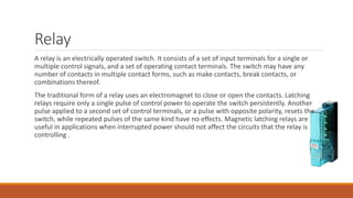
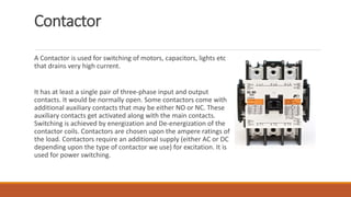
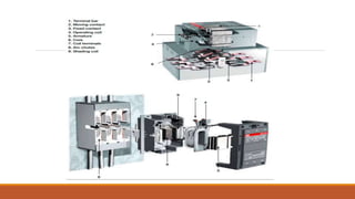
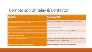
A relay is an electrically operated switch. It consists of a set of input terminals for a single or
multiple control signals, and a set of operating contact terminals. The switch may have any
number of contacts in multiple contact forms, such as make contacts, break contacts, or
combinations thereof.
The traditional form of a relay uses an electromagnet to close or open the contacts. Latching
relays require only a single pulse of control power to operate the switch persistently. Another
pulse applied to a second set of control terminals, or a pulse with opposite polarity, resets the
switch, while repeated pulses of the same kind have no effects. Magnetic latching relays are
useful in applications when interrupted power should not affect the circuits that the relay is
controlling .
Contactor
A Contactor is used for switching of motors, capacitors, lights etc
that drains very high current.
It has at least a single pair of three-phase input and output
contacts. It would be normally open. Some contactors come with
additional auxiliary contacts that may be either NO or NC. These
auxiliary contacts get activated along with the main contacts.
Switching is achieved by energization and De-energization of the
contactor coils. Contactors are chosen upon the ampere ratings of
the load. Contactors require an additional supply (either AC or DC
depending upon the type of contactor we use) for excitation. It is
used for power switching.
Comparison of Relay & Contactor
RELAYS CONTACTOR
Relays are switching devices used in any control circuit for checking a condition
or multiplying the number of contacts available.
Contactors are switching devices used to control power flow to any load.
Relatively smaller in size Larger when compared to Relays
Used in circuits with lower ampacity. (Max 20A) Used in circuits with low and higher ampacity up to 12500A
Mainly used in control and automation circuits, protection circuits and for
switching small electronic circuits.
Used in the switching of motors, capacitors, lights etc.
Consists of at least two NO/NC contacts Consists of a minimum one set of three-phase power contacts and in some cases
additional auxiliary contacts are also provided.
Relays do not have an arc suppression system built-in. Normally, contactors have in- built arc chutes for suppression.
Incident on 11 Sep
OL Info: 08:36 Train driver on trip-181015 group-021 at downline Pakistan Mint (05) report:
Emergency brake (EB) triggered at downward platform Pakistan Mint (05) train cannot move in
RM mode. Train driver take bottom measures”.
As soon the incident was reported ATS playback was checked to find the reason of EB and so far
no abnormality was found from Signaling side .
After Train rescue when train arrived to depot the on-board logs were downloaded to confirm
the EB reason and in the logs EB request wasn’t generated from Signaling side .
Signaling System have redundant equipment available so its unlikely that any malfunction will
impact train operation . Moreover there are Driving control options available and at any time
the degraded modes can be utilized ,
In Actual EB was applied due to RS
Whenever Train is approaching / arriving at platform Traction goes off and brakes are applied .
Same case was in progress and one of the magnetic contactor latch circuit belonging to RS was
partially operated and due to this EB didn’t release and train crew was unable to move the train
in any mode .
Later on train crew released the pressure of the brakes manually to tow it to the Parking Garage
in Depot.

Relay & Magnetic Contactor.pptx

  • 1.
    Relay & Magnetic Contactor THEPURPOSE OF THIS DOCUMENT TO CLARIFY MAIN CONCEPT OF RELAYS AND MAGNETIC CONTACTORS & LESSON LEARNT FOR EB APPLIED ON 11 SEP 2021
  • 2.
    Relay A relay isan electrically operated switch. It consists of a set of input terminals for a single or multiple control signals, and a set of operating contact terminals. The switch may have any number of contacts in multiple contact forms, such as make contacts, break contacts, or combinations thereof. The traditional form of a relay uses an electromagnet to close or open the contacts. Latching relays require only a single pulse of control power to operate the switch persistently. Another pulse applied to a second set of control terminals, or a pulse with opposite polarity, resets the switch, while repeated pulses of the same kind have no effects. Magnetic latching relays are useful in applications when interrupted power should not affect the circuits that the relay is controlling .
  • 4.
    Contactor A Contactor isused for switching of motors, capacitors, lights etc that drains very high current. It has at least a single pair of three-phase input and output contacts. It would be normally open. Some contactors come with additional auxiliary contacts that may be either NO or NC. These auxiliary contacts get activated along with the main contacts. Switching is achieved by energization and De-energization of the contactor coils. Contactors are chosen upon the ampere ratings of the load. Contactors require an additional supply (either AC or DC depending upon the type of contactor we use) for excitation. It is used for power switching.
  • 7.
    Comparison of Relay& Contactor RELAYS CONTACTOR Relays are switching devices used in any control circuit for checking a condition or multiplying the number of contacts available. Contactors are switching devices used to control power flow to any load. Relatively smaller in size Larger when compared to Relays Used in circuits with lower ampacity. (Max 20A) Used in circuits with low and higher ampacity up to 12500A Mainly used in control and automation circuits, protection circuits and for switching small electronic circuits. Used in the switching of motors, capacitors, lights etc. Consists of at least two NO/NC contacts Consists of a minimum one set of three-phase power contacts and in some cases additional auxiliary contacts are also provided. Relays do not have an arc suppression system built-in. Normally, contactors have in- built arc chutes for suppression.
  • 8.
    Incident on 11Sep OL Info: 08:36 Train driver on trip-181015 group-021 at downline Pakistan Mint (05) report: Emergency brake (EB) triggered at downward platform Pakistan Mint (05) train cannot move in RM mode. Train driver take bottom measures”. As soon the incident was reported ATS playback was checked to find the reason of EB and so far no abnormality was found from Signaling side . After Train rescue when train arrived to depot the on-board logs were downloaded to confirm the EB reason and in the logs EB request wasn’t generated from Signaling side . Signaling System have redundant equipment available so its unlikely that any malfunction will impact train operation . Moreover there are Driving control options available and at any time the degraded modes can be utilized ,
  • 10.
    In Actual EBwas applied due to RS Whenever Train is approaching / arriving at platform Traction goes off and brakes are applied . Same case was in progress and one of the magnetic contactor latch circuit belonging to RS was partially operated and due to this EB didn’t release and train crew was unable to move the train in any mode . Later on train crew released the pressure of the brakes manually to tow it to the Parking Garage in Depot.