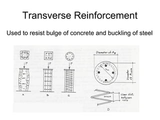
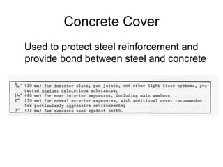
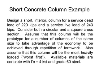
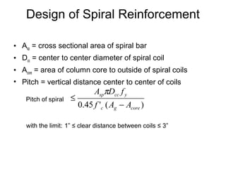
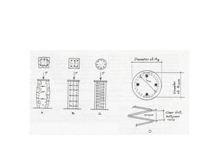
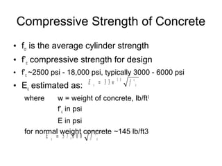
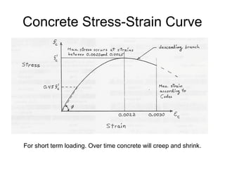
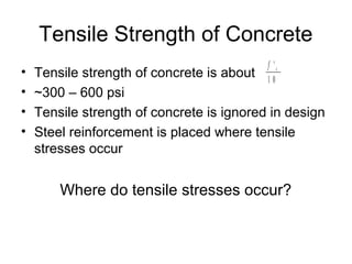
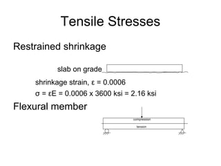
The document discusses the design of reinforced concrete, outlining the key factors such as compressive strength, tensile strength, and stress-strain behavior. It elaborates on the design requirements according to ACI 318, the importance of steel reinforcement, and safety factors for short concrete columns. Additionally, it provides an example of designing a short column to support specific loads and the considerations for spiral reinforcement.


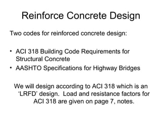
![Reinforcement Ratio
• ρ = As/Ag
• ACI 318 limits on ρ for columns:
0.01≤ρ≤0.08 (practical ρmax = 0.06)
• Substitute ρ=As/Ag and Ag=As+Ac into
equilibrium equation:
P = Ag[ρfy +f’c(1- ρ)]](https://image.slidesharecdn.com/10-reinforcedconcretedesign2-180222094048/85/Reinforced-Concrete-Design-2-14-320.jpg)
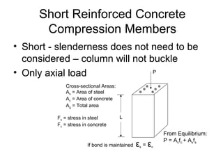
![Short Concrete Columns
P = Ag[ρfy +f’c(1- ρ)]
Safety Factors
• Resistance factor, Ф = 0.65 (tied), Ф = 0.70 (spiral)
• When fc>0.85f’c, over time, concrete will collapse
• Stray moment factor for columns, K1
– K1=0.80 for tied reinforcement
– K1=0.85 for spiral reinforcement
ФPn = Ф K1 Ag[ρfy +0.85f’c(1- ρ)]](https://image.slidesharecdn.com/10-reinforcedconcretedesign2-180222094048/85/Reinforced-Concrete-Design-2-15-320.jpg)
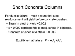
![Short Column Design Equation
ФPn = Ф K1 Ag[ρfy +0.85f’c(1- ρ)]
for design, Pu ≤ ФPn
−
−
≥ c
g
u
cy
f
AK
P
ff
'85.0
)'85.0(
1
1φ
ρ
[ ])1('85.01 ρρφ −+
≥
cy
u
g
ffK
P
A](https://image.slidesharecdn.com/10-reinforcedconcretedesign2-180222094048/85/Reinforced-Concrete-Design-2-16-320.jpg)