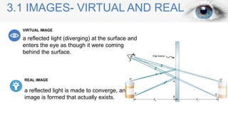
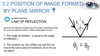
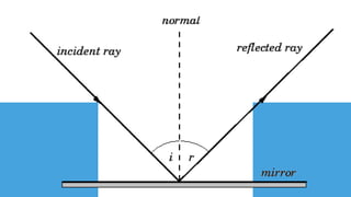
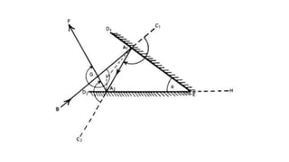
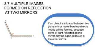
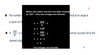
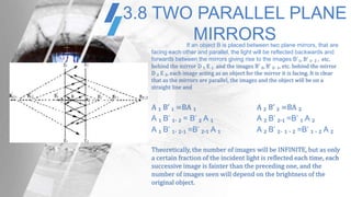
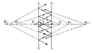
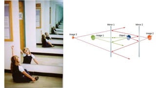
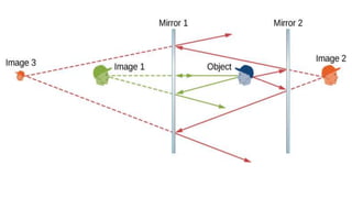
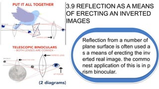
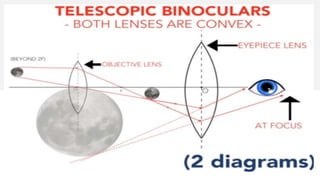
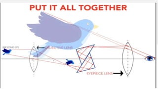
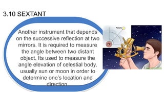
REFLECTION AT A PLANE SURFACECHAPTER 3
3.1 IMAGES- VIRTUAL AND REAL
a reflected light (diverging) at the surface and
enters the eye as though it were coming from
behind the surface.
VIRTUAL IMAGE
a reflected light is made to converge, an
image is formed that actually exists.
REAL IMAGE
3.2 POSITION OF IMAGE FORMED
BY PLANE MIRROR
LAW OF REFLECTION
be determined from
1. The angle of incident i is equal to the angle
of reflection f.
2. The incident ray, the rerflect ray and the nor
mal at the same point of incidence, lie in the sa
me plane..
governs the reflection of light-rays off smooth conducting surfac
es, such as polished metal or metal-coated glass mirrors.
3.3 FIELD OF VIEW OF A PLANE MIRROR
FIELD OF VIEW
is the extend of image in a plane mirror that
can be seen by an eye in any position will de
pend on the size of the mirror and the positio
n of the eye
Q'R'=DE x OB'/OA=QR
3.6 DEVIATION ON REFLECTION AT TWO
MIRRORS IN SUCCESSION
In this figure, the total deviation of the ray
=∠C₁ A₁ A₂ + ∠C₂ A₂ F
=2(∠EA₁ A₂ + ∠E A₂ A₁ ) =2 ∠ A₁ EH
Therefore, total deviation = 2(180° -a) where a is the angle between the
mirrors.
Successive reflection from a two mirrors is used in all possible cases where
considerable accuracy is required in the direction of a reflected beam. Providing
the angle between the reflectors is accurately fixed, and this is frequently done
by making them the surfaces of a prism, the correct placing of the mirrors with
respect of the incident light need not be made with any great accuracy.
3.7 MULTIPLE IMAGES
FORMED ON REFLECTION
AT TWO MIRRORS
If an object is situated between two
plane mirror more than two directs
image will be formed, because
some of light reflected at one
mirror may be again reflected at
the other mirror.
3.8 TWO PARALLEL PLANE
MIRRORSIf an object B is placed between two plane mirrors, that are
facing each other and parallel, the light will be reflected backwards and
forwards between the mirrors giving rise to the images B’₁, B’ ₁. ₂ , etc.
behind the mirror D ₁ E ₁ and the images B’ ₂, B’ ₂. ₁, etc. behind the mirror
D ₂ E ₂, each image acting as an object for the mirror it is facing. It is clear
that as the mirrors are parallel, the images and the object will be on a
straight line and
A ₁ B’ ₁ =BA ₁ A ₂ B’ ₂ =BA ₂
A ₁ B’ ₁. ₂ = B’ ₂ A ₁ A ₂ B’ ₂.₁ =B’ ₁ A ₂
A ₁ B’ ₁. ₂.₁ =B’ ₂.₁ A ₁ A ₂ B’ ₂. ₁ . ₂ =B’ ₁ . ₂ A ₂
Theoretically, the number of images will be INFINITE, but as only
a certain fraction of the incident light is reflected each time, each
successive image is fainter than the preceding one, and the
number of images seen will depend on the brightness of the
original object.
3.9 REFLECTION AS A MEANS
OF ERECTING AN INVERTED
IMAGES
Reflection from a number of
plane surface is often used a
s a means of erecting the inv
erted real image. the commo
nest application of this is in p
rism binocular.
3.10 SEXTANT
Another instrument that depends
on the successive reflection at two
mirrors. It is required to measure
the angle between two distant
object. Its used to measure the
angle elevation of celestial body,
usually sun or moon in order to
determine one’s location and
direction.

Reflection at plane surface

  • 1.
    REFLECTION AT APLANE SURFACECHAPTER 3
  • 2.
    3.1 IMAGES- VIRTUALAND REAL a reflected light (diverging) at the surface and enters the eye as though it were coming from behind the surface. VIRTUAL IMAGE a reflected light is made to converge, an image is formed that actually exists. REAL IMAGE
  • 4.
    3.2 POSITION OFIMAGE FORMED BY PLANE MIRROR LAW OF REFLECTION be determined from 1. The angle of incident i is equal to the angle of reflection f. 2. The incident ray, the rerflect ray and the nor mal at the same point of incidence, lie in the sa me plane.. governs the reflection of light-rays off smooth conducting surfac es, such as polished metal or metal-coated glass mirrors.
  • 6.
    3.3 FIELD OFVIEW OF A PLANE MIRROR FIELD OF VIEW is the extend of image in a plane mirror that can be seen by an eye in any position will de pend on the size of the mirror and the positio n of the eye Q'R'=DE x OB'/OA=QR
  • 9.
    3.6 DEVIATION ONREFLECTION AT TWO MIRRORS IN SUCCESSION In this figure, the total deviation of the ray =∠C₁ A₁ A₂ + ∠C₂ A₂ F =2(∠EA₁ A₂ + ∠E A₂ A₁ ) =2 ∠ A₁ EH Therefore, total deviation = 2(180° -a) where a is the angle between the mirrors. Successive reflection from a two mirrors is used in all possible cases where considerable accuracy is required in the direction of a reflected beam. Providing the angle between the reflectors is accurately fixed, and this is frequently done by making them the surfaces of a prism, the correct placing of the mirrors with respect of the incident light need not be made with any great accuracy.
  • 11.
    3.7 MULTIPLE IMAGES FORMEDON REFLECTION AT TWO MIRRORS If an object is situated between two plane mirror more than two directs image will be formed, because some of light reflected at one mirror may be again reflected at the other mirror.
  • 13.
    3.8 TWO PARALLELPLANE MIRRORSIf an object B is placed between two plane mirrors, that are facing each other and parallel, the light will be reflected backwards and forwards between the mirrors giving rise to the images B’₁, B’ ₁. ₂ , etc. behind the mirror D ₁ E ₁ and the images B’ ₂, B’ ₂. ₁, etc. behind the mirror D ₂ E ₂, each image acting as an object for the mirror it is facing. It is clear that as the mirrors are parallel, the images and the object will be on a straight line and A ₁ B’ ₁ =BA ₁ A ₂ B’ ₂ =BA ₂ A ₁ B’ ₁. ₂ = B’ ₂ A ₁ A ₂ B’ ₂.₁ =B’ ₁ A ₂ A ₁ B’ ₁. ₂.₁ =B’ ₂.₁ A ₁ A ₂ B’ ₂. ₁ . ₂ =B’ ₁ . ₂ A ₂ Theoretically, the number of images will be INFINITE, but as only a certain fraction of the incident light is reflected each time, each successive image is fainter than the preceding one, and the number of images seen will depend on the brightness of the original object.
  • 17.
    3.9 REFLECTION ASA MEANS OF ERECTING AN INVERTED IMAGES Reflection from a number of plane surface is often used a s a means of erecting the inv erted real image. the commo nest application of this is in p rism binocular.
  • 20.
    3.10 SEXTANT Another instrumentthat depends on the successive reflection at two mirrors. It is required to measure the angle between two distant object. Its used to measure the angle elevation of celestial body, usually sun or moon in order to determine one’s location and direction.

Editor's Notes

  • #3 If the reflected rays are extended backward behind the mirror (see dashed lines), they seem to originate from point Q. This is where the image of point P is located. If we repeat this process for point P'P', we obtain its image at point Q'. You should convince yourself by using basic geometry that the image height (the distance from Q to Q') is the same as the object height (the distance from P to P'). By forming images of all points of the object, we obtain an upright image of the object behind the mirror. A real image can be seen by placing a screen at the image location, or it can be turned into a virtual image that can be viewed directly with the aid of a second lens or mirror. VIRTUAL IMAGES - virtual image appears the same distance behind the plane mirror as the object is in front of the mirror. virtual images are images that are formed in locations where light does not actually reach. Light does not actually pass through the location on the other side of the mirror; it only appears to an observer as though the light is coming from this location. Whenever a mirror (whether a plane mirror or otherwise) creates an image that is virtual, it will be located behind the mirror where light does not really come from. A virtual image (as opposed to a real image) is produced by an optical system (a combination of lenses and/or mirrors) when light rays from a source do not cross to form an image. Instead they can be ‘traced back’ to a point behind the lens or mirror. Virtual images can be seen directly without using a screen for projection. REAL IMAGE - is produced by an optical system (a combination of lenses and/or mirrors) when light rays from a source cross to form an image. Light rays diverge from the real image in the same way that they diverge from the source. A mirror is an optical device that uses reflection to deflect and focus the path of light rays, producing either a real or virtual image of a source object. Left: A flat (or plane) mirror creates a virtual image of any object placed in front of it. Right: The virtual images are the same distance from the mirror as the original objects.
  • #4 Notice that the reflected rays appear to the observer to come directly from the image behind the mirror. In reality, these rays come from the points on the mirror where they are reflected. The image behind the mirror is called a virtual image because it cannot be projected onto a screen—the rays only appear to originate from a common point behind the mirror. If you walk behind the mirror, you cannot see the image, because the rays do not go there. However, in front of the mirror, the rays behave exactly as if they come from behind the mirror, so that is where the virtual image is located.
  • #5 Note that we use the law of reflection to construct the reflected rays. The law of reflection also holds for non-plane mirrors, provided that the normal at any point on the mirror is understood to be the outward pointing normal to the local tangent plane of the mirror at that point. For rough surfaces, the law of reflection remains valid. It predicts that rays incident at slightly different points on the surface are reflected in completely different directions, because the normal to a rough surface varies in direction very strongly from point to point on the surface. This type of reflection is called diffuse reflection, and is what enables us to see non-shiny objects.
  • #14 IMAGES AND OBJECT WILL BE ON STRAIGHT LINE AND INFINITE If an object is situated in front of two mirrors, you may see images in both mirrors. In addition, the image in the first mirror may act as an object for the second mirror, so the second mirror may form an image of the image. If the mirrors are placed parallel to each other and the object is placed at a point other than the midpoint between them, then this process of image-of-an-image continues without end, as you may have noticed when standing in a hallway with mirrors on each side. This is shown in Figure 2.1.2, which shows three images produced by the blue object. Notice that each reflection reverses front and back, just like pulling a right-hand glove inside out produces a left-hand glove (this is why a reflection of your right hand is a left hand). Thus, the fronts and backs of images 1 and 2 are both inverted with respect to the object, and the front and back of image 3 is inverted with respect to image 2, which is the object for image 3.