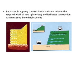
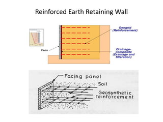
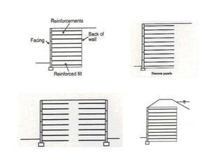
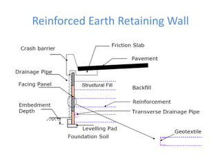
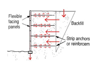
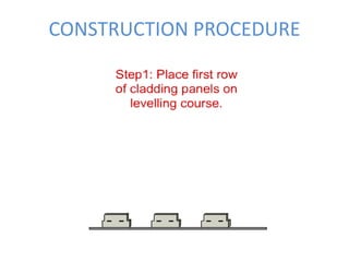
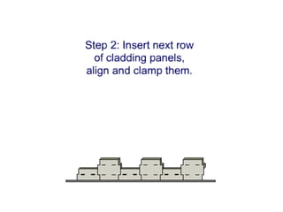
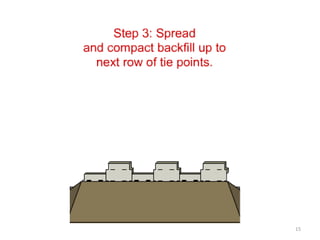
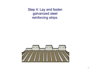
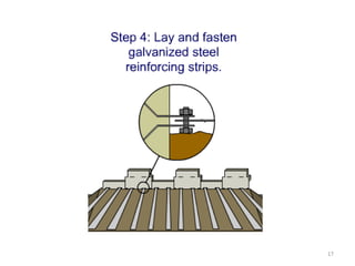
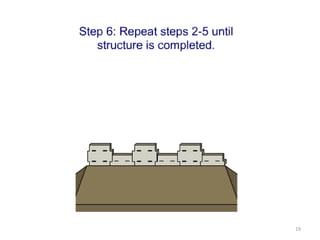
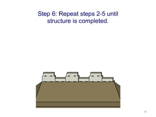
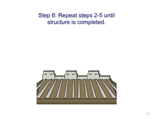
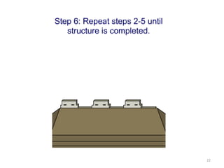
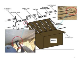
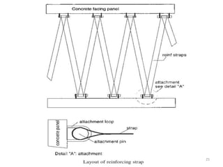
REINFORCED EARTH RETAINING
WALLS & SLOPES
SOUMYA S GROUND IMPROVEMENT TECHNIQUES
• Important in highway construction as their use reduces the
required width of new right-of-way and facilitates construction
within existing limited right-of-way.
Reinforced embankments over soft foundations
• A cost-effective alternative to traditional techniques for
constructing earthen embankments over low strength
foundations
Reinforced Earth Retaining Wall
Load Transfer Mechanism
 The flexible reinforcement interacts frictionally with the
soil resisting the shear stresses in the soil mass
 The shear stress at the interface of the soil and the
reinforcement generates strains in the reinforcement
and a tensile force is mobilised in the reinforcement
 If this tensile force exceeds the tensile capacity of the
reinforcement, rupture failure occurs – Tensile failure
 If deformations are high or if the interface is smooth, it
is likely that a slip occurs between the soil and
reinforcement – Pullout Failure
 For stability, Tensile failure and Pullout failure to be
examined
Principles
• If a vertical stress sv is applied on a soil element, it undergoes
a vertical compression (dv) associated with a lateral
deformation (dh).
• If a reinforcement is added to the soil in the form of horizontal
layers, the soil element will be restrained against lateral
deformation as it acted by a lateral force.
sv
dh = 0 with
reinforcement
Reinforcement
sv
dv
dh
• The lateral force required for zero lateral deflection is equal to
the lateral earth pressure at rest, ie K0. δv
• The lateral force required to keep the element in limiting
equilibrium is equal to Ka. δv.
ie (δh)min = Ka. δv
CONSTRUCTION PROCEDURE
15
16
17
18
19
20
21
22
23
25
Facing Panels
• Panel Thickness -140, 160 and 180mm
• When maximum wall height is 8m, use 140mm thick panel.
Otherwise use 160mm thick panel.
26
THANK YOU!!

Re retaining walls1

  • 1.
    REINFORCED EARTH RETAINING WALLS& SLOPES SOUMYA S GROUND IMPROVEMENT TECHNIQUES
  • 2.
    • Important inhighway construction as their use reduces the required width of new right-of-way and facilitates construction within existing limited right-of-way.
  • 3.
    Reinforced embankments oversoft foundations • A cost-effective alternative to traditional techniques for constructing earthen embankments over low strength foundations
  • 4.
  • 6.
  • 7.
    Load Transfer Mechanism The flexible reinforcement interacts frictionally with the soil resisting the shear stresses in the soil mass  The shear stress at the interface of the soil and the reinforcement generates strains in the reinforcement and a tensile force is mobilised in the reinforcement  If this tensile force exceeds the tensile capacity of the reinforcement, rupture failure occurs – Tensile failure  If deformations are high or if the interface is smooth, it is likely that a slip occurs between the soil and reinforcement – Pullout Failure  For stability, Tensile failure and Pullout failure to be examined
  • 8.
    Principles • If avertical stress sv is applied on a soil element, it undergoes a vertical compression (dv) associated with a lateral deformation (dh). • If a reinforcement is added to the soil in the form of horizontal layers, the soil element will be restrained against lateral deformation as it acted by a lateral force. sv dh = 0 with reinforcement Reinforcement sv dv dh
  • 9.
    • The lateralforce required for zero lateral deflection is equal to the lateral earth pressure at rest, ie K0. δv • The lateral force required to keep the element in limiting equilibrium is equal to Ka. δv. ie (δh)min = Ka. δv
  • 13.
  • 15.
  • 16.
  • 17.
  • 18.
  • 19.
  • 20.
  • 21.
  • 22.
  • 23.
  • 25.
  • 26.
    Facing Panels • PanelThickness -140, 160 and 180mm • When maximum wall height is 8m, use 140mm thick panel. Otherwise use 160mm thick panel. 26
  • 27.