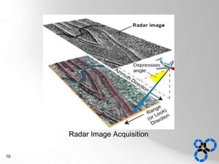
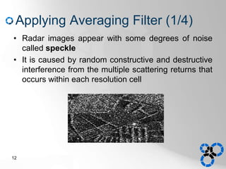
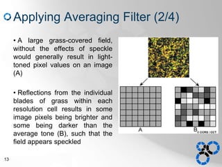
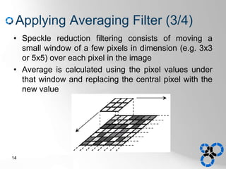
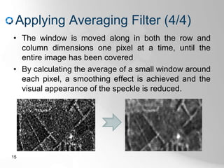
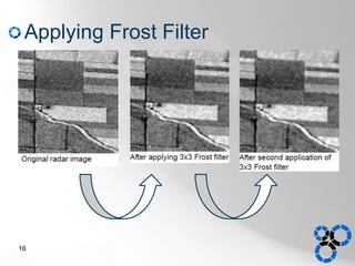
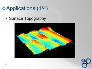
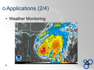
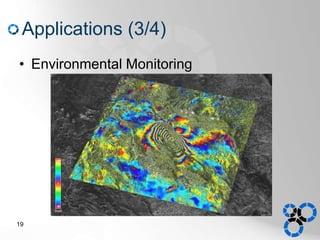
Radar Image
Jubayer Al Mahmud
Department of Computer Science & Engineering
University of Dhaka
Outline
• Definition
• Properties
• Image formation devices
• Acquisition of radar images
• Sample output
– Applying averaging filter
– Applying frost filter
• Applications
2
Definition
• Radar
– A system for detecting an object by sending
out pulses of high-frequency electromagnetic
waves that are reflected off the object back to
the source
– Detects presence, direction, distance and
speed of the object
• Radar Image
– A two dimensional image produced by a radar
system
3
Properties of Radar Image
• Composed of many dots
• Each pixel in the radar image represents the
radar backscatter for that area on the ground
• Brighter areas represent high backscatter
• Darker areas represents low backscatter
• Reveals information about the surface terrain
and its physical properties
4
Radar Image
5
Image Formation Devices (1/3)
• Real Aperture Radar (RAR)
– Transmits a narrow angle beam of radio wave
pulse in the range and receives the
backscattering from the targets which is
transformed to a radar image
– The reflected pulses are arranged in the order
of return time from the targets
– Resolution depends on the pulse width
6
Image Formation Devices (2/3)
• Synthetic Aperture Radar (SAR)
– Moves a real aperture through a series of
positions along the objects to provide
distinctive long term coherent signal variations
– Obtains higher resolution
• Inverse Synthetic Aperture Radar
– Same as SAR but produces higher resolution
on two and three dimensional images
7
Image Formation Devices (3/3)
• Laser Radar
– A remote sensing technology that measures
distance by illuminating a target with a laser
and analyzing the reflected light
– Used for multi-dimensional imaging and
information gathering
• Mono-pulse Radar
– Utilizes ISAR techniques
– Obtains 3 views of an 3D object
8
Acquisition of Radar Image
• An imaging radar system emits discrete radar
pulses that are directed to one side
• The microwaves interact with surface objects
and some of them return to the radar antenna
• The system records the echoes from the the
terrain and their variation in strength with travel
time
• The returned signals are positioned according to
their time
9
Formation of Radar
Images
Radar Image Acquisition
10
Sample output
11
Applying Averaging Filter (1/4)
• Radar images appear with some degrees of noise
called speckle
• It is caused by random constructive and destructive
interference from the multiple scattering returns that
occurs within each resolution cell
12
Applying Averaging Filter (2/4)
• A large grass-covered field,
without the effects of speckle
would generally result in light-
toned pixel values on an image
(A)
• Reflections from the individual
blades of grass within each
resolution cell results in some
image pixels being brighter and
some being darker than the
average tone (B), such that the
field appears speckled
13
Applying Averaging Filter (3/4)
• Speckle reduction filtering consists of moving a
small window of a few pixels in dimension (e.g. 3x3
or 5x5) over each pixel in the image
• Average is calculated using the pixel values under
that window and replacing the central pixel with the
new value
14
Applying Averaging Filter (4/4)
• The window is moved along in both the row and
column dimensions one pixel at a time, until the
entire image has been covered
• By calculating the average of a small window around
each pixel, a smoothing effect is achieved and the
visual appearance of the speckle is reduced.
15
Applying Frost Filter
16
Applications (1/4)
• Surface Topography
17
Applications (2/4)
• Weather Monitoring
18
Applications (3/4)
• Environmental Monitoring
19
Application (4/4)
• Through Wall Radar Imaging
20
Thank You
21

Radar Image Processing

  • 1.
    Radar Image Jubayer AlMahmud Department of Computer Science & Engineering University of Dhaka
  • 2.
    Outline • Definition • Properties •Image formation devices • Acquisition of radar images • Sample output – Applying averaging filter – Applying frost filter • Applications 2
  • 3.
    Definition • Radar – Asystem for detecting an object by sending out pulses of high-frequency electromagnetic waves that are reflected off the object back to the source – Detects presence, direction, distance and speed of the object • Radar Image – A two dimensional image produced by a radar system 3
  • 4.
    Properties of RadarImage • Composed of many dots • Each pixel in the radar image represents the radar backscatter for that area on the ground • Brighter areas represent high backscatter • Darker areas represents low backscatter • Reveals information about the surface terrain and its physical properties 4
  • 5.
  • 6.
    Image Formation Devices(1/3) • Real Aperture Radar (RAR) – Transmits a narrow angle beam of radio wave pulse in the range and receives the backscattering from the targets which is transformed to a radar image – The reflected pulses are arranged in the order of return time from the targets – Resolution depends on the pulse width 6
  • 7.
    Image Formation Devices(2/3) • Synthetic Aperture Radar (SAR) – Moves a real aperture through a series of positions along the objects to provide distinctive long term coherent signal variations – Obtains higher resolution • Inverse Synthetic Aperture Radar – Same as SAR but produces higher resolution on two and three dimensional images 7
  • 8.
    Image Formation Devices(3/3) • Laser Radar – A remote sensing technology that measures distance by illuminating a target with a laser and analyzing the reflected light – Used for multi-dimensional imaging and information gathering • Mono-pulse Radar – Utilizes ISAR techniques – Obtains 3 views of an 3D object 8
  • 9.
    Acquisition of RadarImage • An imaging radar system emits discrete radar pulses that are directed to one side • The microwaves interact with surface objects and some of them return to the radar antenna • The system records the echoes from the the terrain and their variation in strength with travel time • The returned signals are positioned according to their time 9
  • 10.
    Formation of Radar Images RadarImage Acquisition 10
  • 11.
  • 12.
    Applying Averaging Filter(1/4) • Radar images appear with some degrees of noise called speckle • It is caused by random constructive and destructive interference from the multiple scattering returns that occurs within each resolution cell 12
  • 13.
    Applying Averaging Filter(2/4) • A large grass-covered field, without the effects of speckle would generally result in light- toned pixel values on an image (A) • Reflections from the individual blades of grass within each resolution cell results in some image pixels being brighter and some being darker than the average tone (B), such that the field appears speckled 13
  • 14.
    Applying Averaging Filter(3/4) • Speckle reduction filtering consists of moving a small window of a few pixels in dimension (e.g. 3x3 or 5x5) over each pixel in the image • Average is calculated using the pixel values under that window and replacing the central pixel with the new value 14
  • 15.
    Applying Averaging Filter(4/4) • The window is moved along in both the row and column dimensions one pixel at a time, until the entire image has been covered • By calculating the average of a small window around each pixel, a smoothing effect is achieved and the visual appearance of the speckle is reduced. 15
  • 16.
  • 17.
  • 18.
  • 19.
  • 20.
    Application (4/4) • ThroughWall Radar Imaging 20
  • 21.