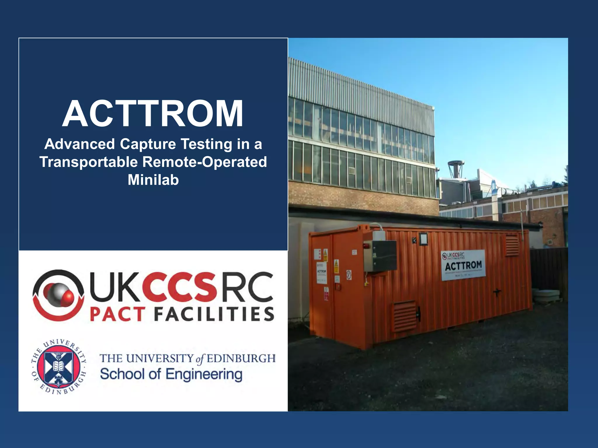
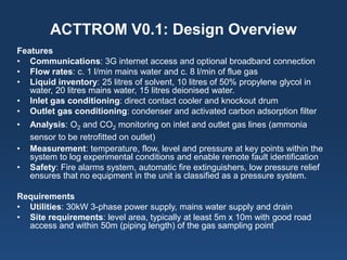
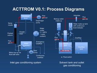
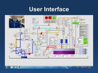
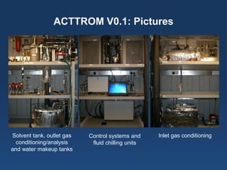
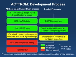
ACTTROM Advanced Capture Testing in a Transportable Remote-Operated Minilab
ACTTROM V0.1: Design Overview 
Features 
• 
Communications: 3G internet access and optional broadband connection 
• 
Flow rates: c. 1 l/min mains water and c. 8 l/min of flue gas 
• 
Liquid inventory: 25 litres of solvent, 10 litres of 50% propylene glycol in water, 20 litres mains water, 15 litres deionised water. 
• 
Inlet gas conditioning: direct contact cooler and knockout drum 
• 
Outlet gas conditioning: condenser and activated carbon adsorption filter 
• 
Analysis: O2 and CO2 monitoring on inlet and outlet gas lines (ammonia sensor to be retrofitted on outlet) 
• 
Measurement: temperature, flow, level and pressure at key points within the system to log experimental conditions and enable remote fault identification 
• 
Safety: Fire alarms system, automatic fire extinguishers, low pressure relief ensures that no equipment in the unit is classified as a pressure system. 
Requirements 
• 
Utilities: 30kW 3-phase power supply, mains water supply and drain 
• 
Site requirements: level area, typically at least 5m x 10m with good road access and within 50m (piping length) of the gas sampling point
ACTTROM V0.1: Process Diagrams 
Water 
Inventory 
Knockout 
drum 
Spray 
nozzle 
Packed 
column 
Flue 
gas in 
Mains top-up via 
float ball valve 
Continuous 
overflow 
Emergency 
overflow 
Water 
cooler 
(1:1 MPG 
+ water 
coolant) 
Gear 
pump 
Diaphragm 
pump 
Flue 
gas out 
Droplet 
drain 
Solvent 
tank 
Overflow 
tank 
Air stones 
Float switch 
Reflux 
condenser 
Adsorber 
Flue 
gas out 
Flue 
gas in 
Water make-up tank 
with continuous 
level indicator 
Overflow 
Backup water 
make-up 
Inlet gas conditioning system 
Solvent tank and outlet 
gas conditioning
Current Status 
• 
Build has been completed. 
• 
Provisionally approved by Zurich Engineering, pending imminent completion of paperwork. 
• 
Cause-and-effect matrices for the operation of the unit have been drafted and approved, together with a list of error codes (around 400 of them). 
• 
User interface designed (see slide 6). 
• 
Programming complete – state machine architecture automates, controls and checks the process (see slide 7) and handles c.150 variables. 
• 
After rectifying some minor faults, satisfactory performance has been demonstrated with water. 
• 
Framework for future development of the unit has been established (see slide 9). 
• 
Process items have been labelled. 
• 
Drafting of manual is nearly complete.
User Interface
ACTTROM V0.1: Pictures 
Solvent tank, outlet gas conditioning/analysis 
and water makeup tanks 
Inlet gas conditioning 
Control systems and 
fluid chilling units
Program Flow Diagram
Example Code 
Fault 
Simulation 
Analog 
Output 
Condition 
Met? 
Next 
Task 
Nested case structures
ACTTROM: Development Process 
HS1: Preliminary design report 
& identification of issues 
HS2: HAZID study 
HS5: Site acceptance testing 
HS4: check constructed apparatus 
conforms with law & agreed design 
DSEAR assessment 
HS3: HAZOP study 
HS6: Review 
Declaration of conformity & 
third party inspection 
Construction/modification and 
Commissioning of apparatus 
ABB six-stage Hazard Study process 
Parallel Processes 
Process must be repeated for every major modification or integration of new apparatus 
Complete 
Underway 
Not yet started 
ACTTROM 
V0.1 status
Next steps 
• 
Get on site! 
• 
Peterhead running hours uncertain, awaiting developments (and other UK power plants uncertain running plans) 
• 
Have approached steel works but competing priorities 
• 
University natural gas CHP an alternative 
• 
Design also of interest overseas

ACTTROM - talk by Roger Watson, University of Edinburgh, at the opening of the UKCCSRC PACT Beighton facility

  • 1.
    ACTTROM Advanced CaptureTesting in a Transportable Remote-Operated Minilab
  • 2.
    ACTTROM V0.1: DesignOverview Features • Communications: 3G internet access and optional broadband connection • Flow rates: c. 1 l/min mains water and c. 8 l/min of flue gas • Liquid inventory: 25 litres of solvent, 10 litres of 50% propylene glycol in water, 20 litres mains water, 15 litres deionised water. • Inlet gas conditioning: direct contact cooler and knockout drum • Outlet gas conditioning: condenser and activated carbon adsorption filter • Analysis: O2 and CO2 monitoring on inlet and outlet gas lines (ammonia sensor to be retrofitted on outlet) • Measurement: temperature, flow, level and pressure at key points within the system to log experimental conditions and enable remote fault identification • Safety: Fire alarms system, automatic fire extinguishers, low pressure relief ensures that no equipment in the unit is classified as a pressure system. Requirements • Utilities: 30kW 3-phase power supply, mains water supply and drain • Site requirements: level area, typically at least 5m x 10m with good road access and within 50m (piping length) of the gas sampling point
  • 3.
    ACTTROM V0.1: ProcessDiagrams Water Inventory Knockout drum Spray nozzle Packed column Flue gas in Mains top-up via float ball valve Continuous overflow Emergency overflow Water cooler (1:1 MPG + water coolant) Gear pump Diaphragm pump Flue gas out Droplet drain Solvent tank Overflow tank Air stones Float switch Reflux condenser Adsorber Flue gas out Flue gas in Water make-up tank with continuous level indicator Overflow Backup water make-up Inlet gas conditioning system Solvent tank and outlet gas conditioning
  • 4.
    Current Status • Build has been completed. • Provisionally approved by Zurich Engineering, pending imminent completion of paperwork. • Cause-and-effect matrices for the operation of the unit have been drafted and approved, together with a list of error codes (around 400 of them). • User interface designed (see slide 6). • Programming complete – state machine architecture automates, controls and checks the process (see slide 7) and handles c.150 variables. • After rectifying some minor faults, satisfactory performance has been demonstrated with water. • Framework for future development of the unit has been established (see slide 9). • Process items have been labelled. • Drafting of manual is nearly complete.
  • 5.
  • 6.
    ACTTROM V0.1: Pictures Solvent tank, outlet gas conditioning/analysis and water makeup tanks Inlet gas conditioning Control systems and fluid chilling units
  • 7.
  • 8.
    Example Code Fault Simulation Analog Output Condition Met? Next Task Nested case structures
  • 9.
    ACTTROM: Development Process HS1: Preliminary design report & identification of issues HS2: HAZID study HS5: Site acceptance testing HS4: check constructed apparatus conforms with law & agreed design DSEAR assessment HS3: HAZOP study HS6: Review Declaration of conformity & third party inspection Construction/modification and Commissioning of apparatus ABB six-stage Hazard Study process Parallel Processes Process must be repeated for every major modification or integration of new apparatus Complete Underway Not yet started ACTTROM V0.1 status
  • 10.
    Next steps • Get on site! • Peterhead running hours uncertain, awaiting developments (and other UK power plants uncertain running plans) • Have approached steel works but competing priorities • University natural gas CHP an alternative • Design also of interest overseas