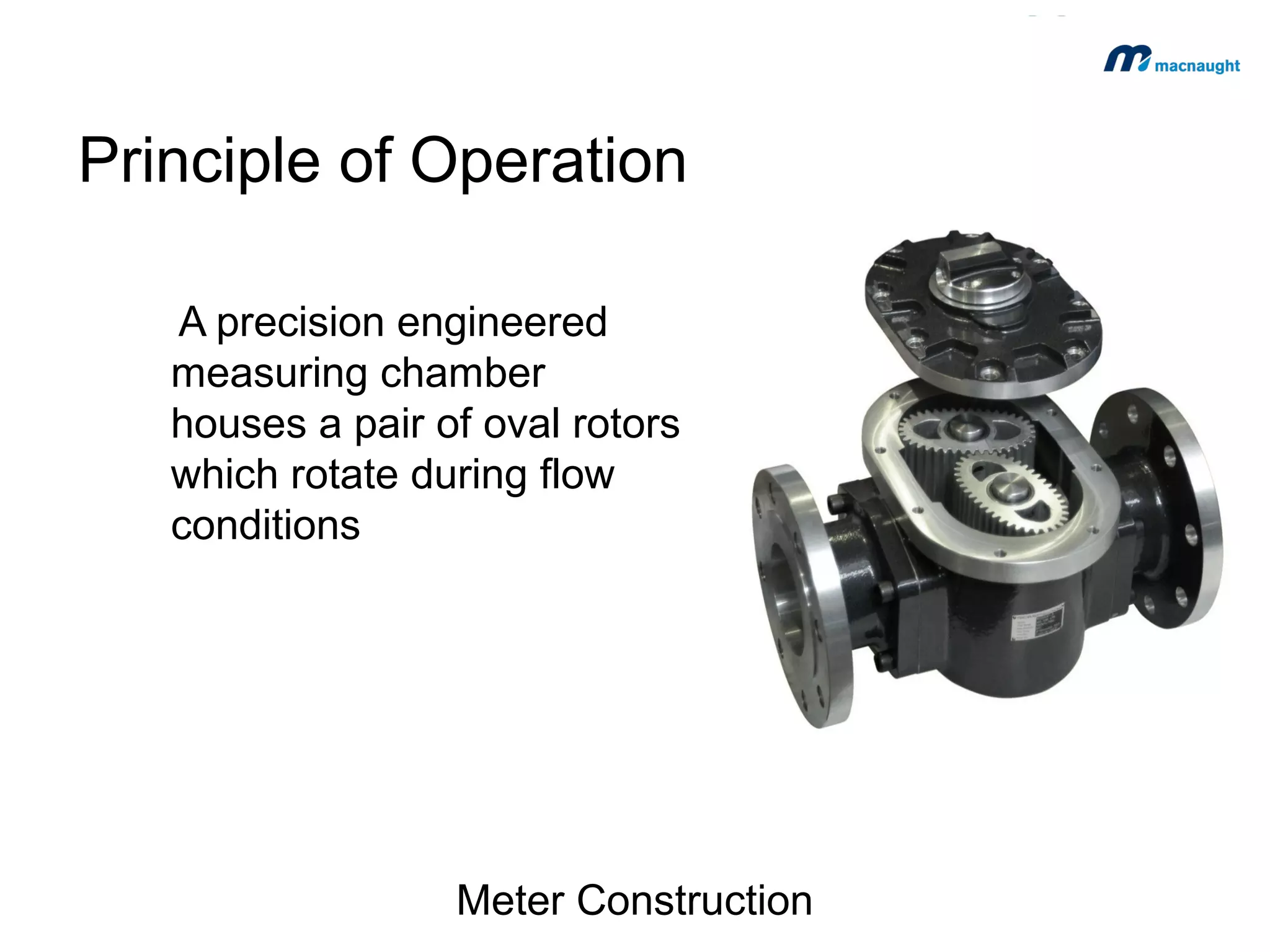
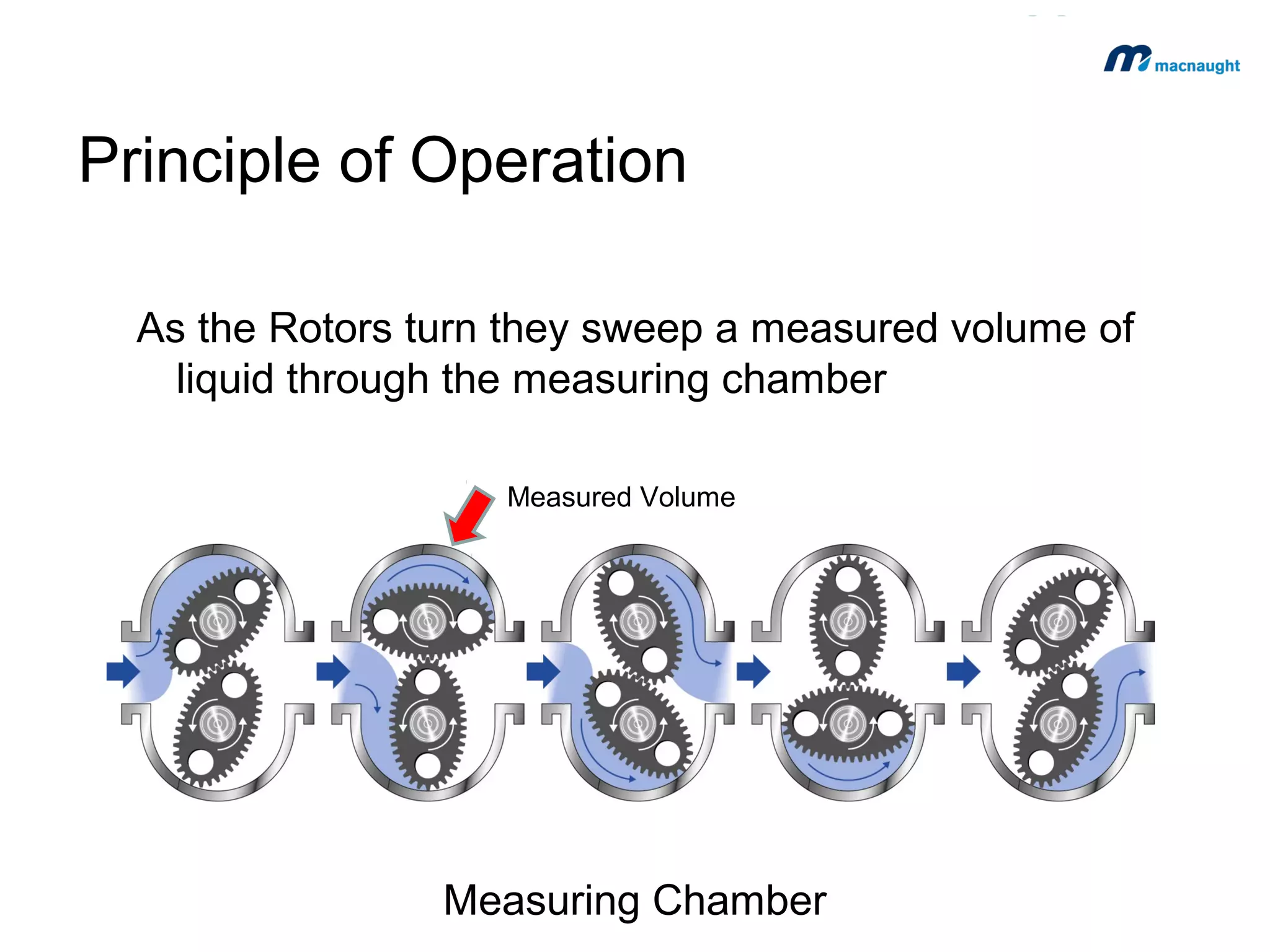
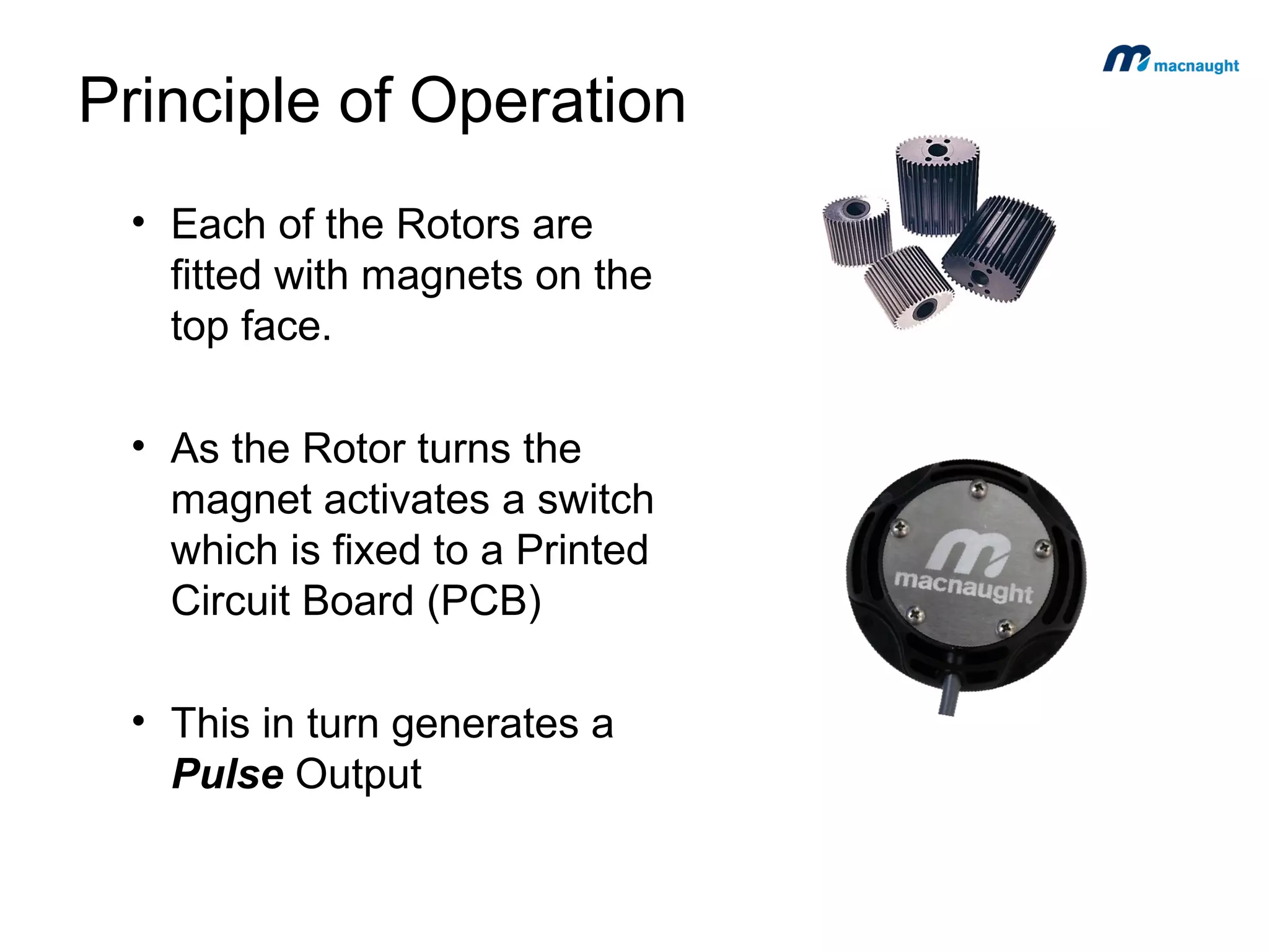
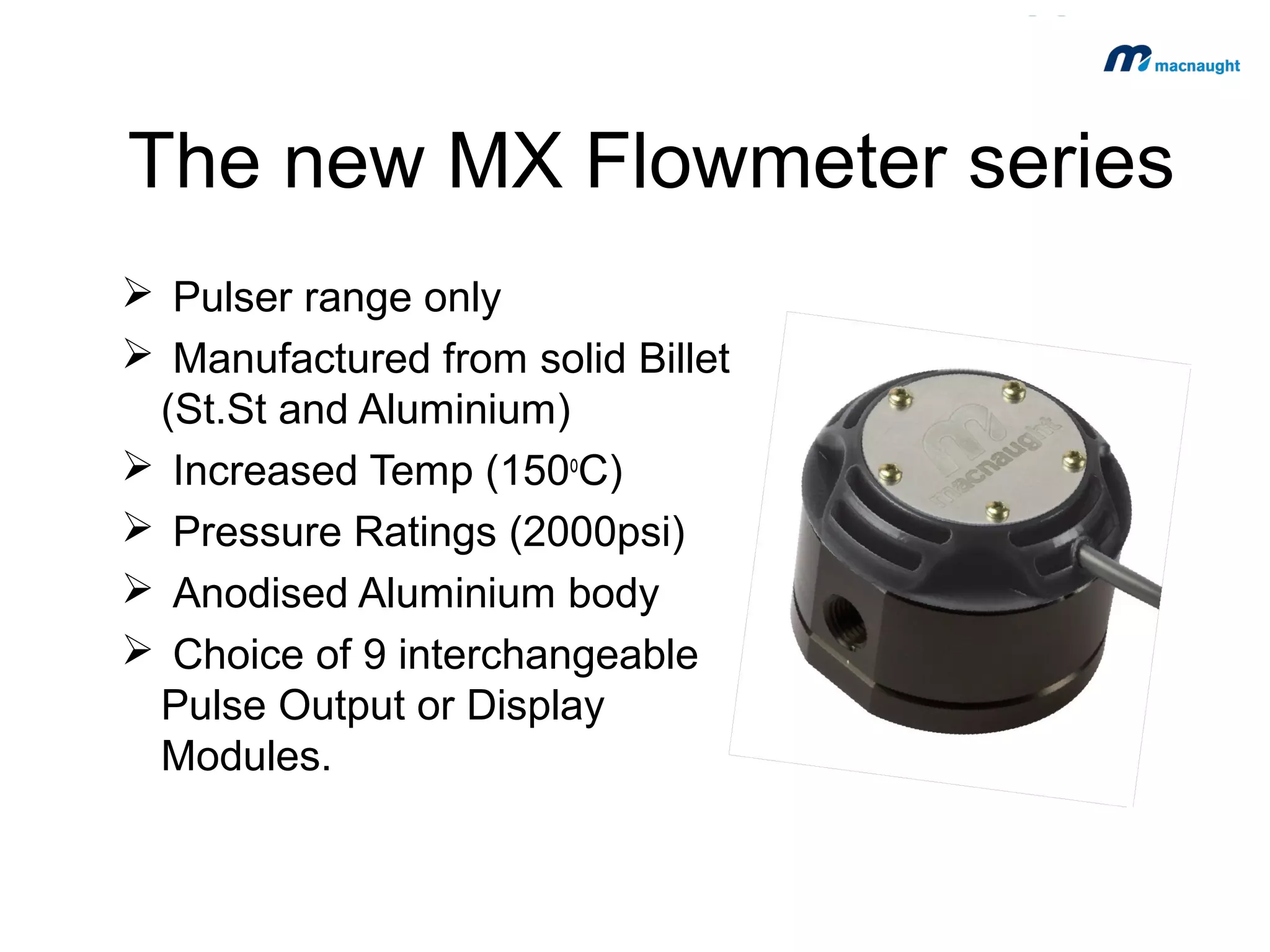
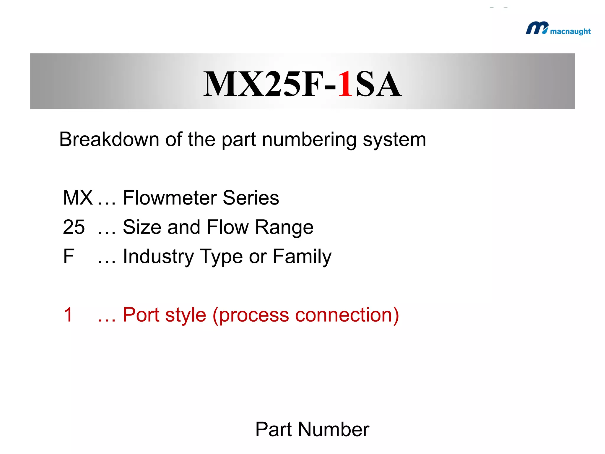
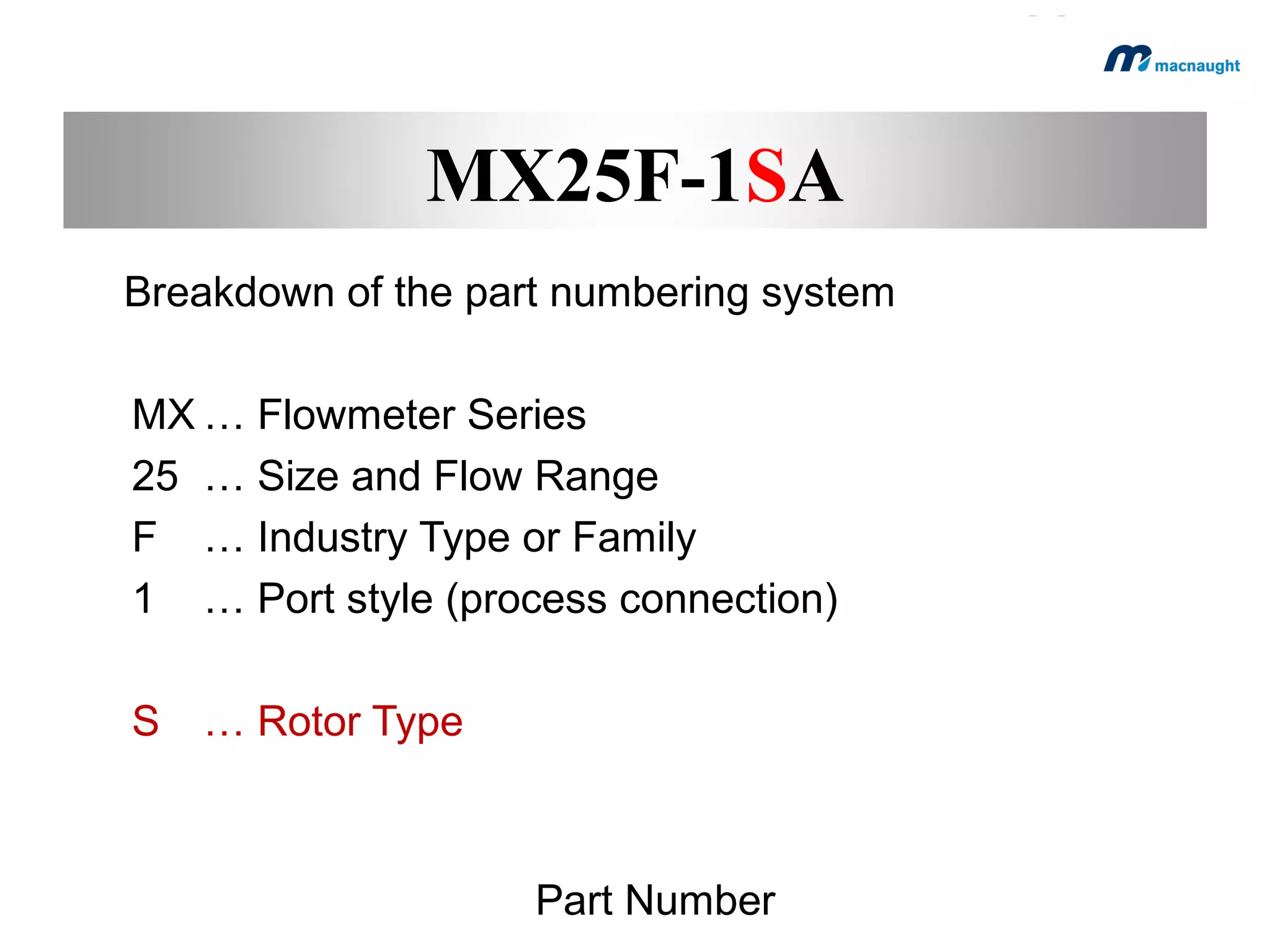
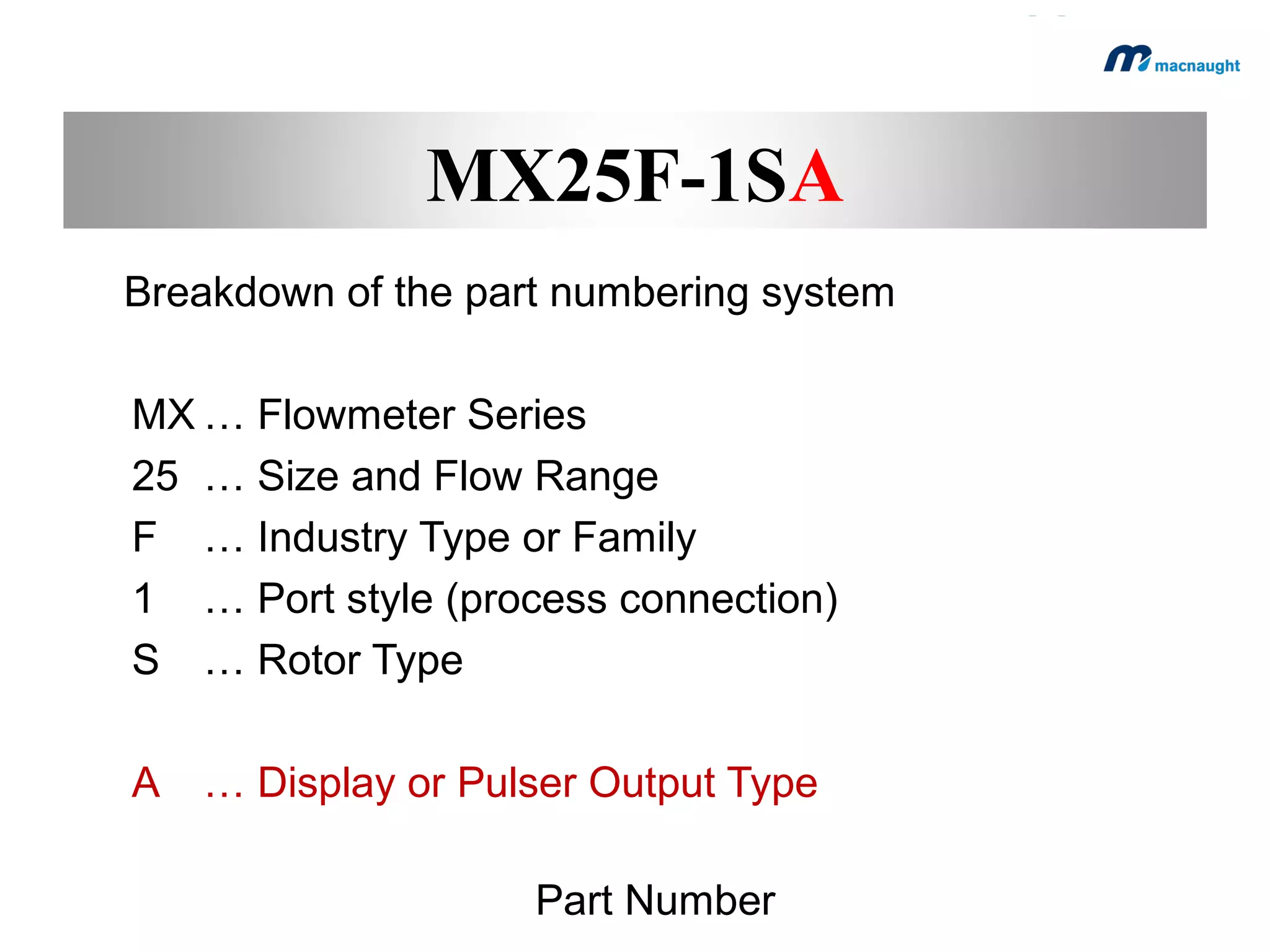
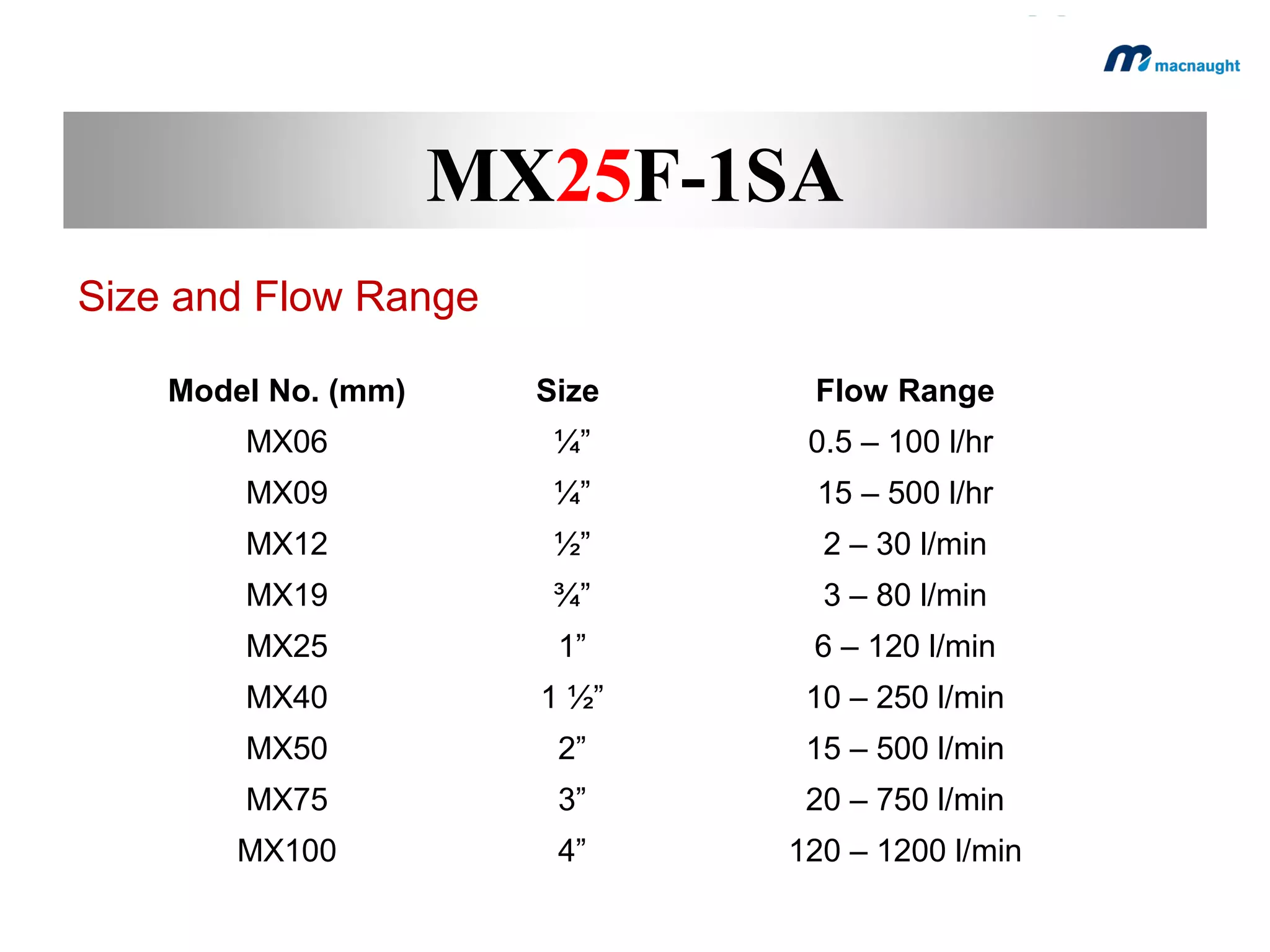
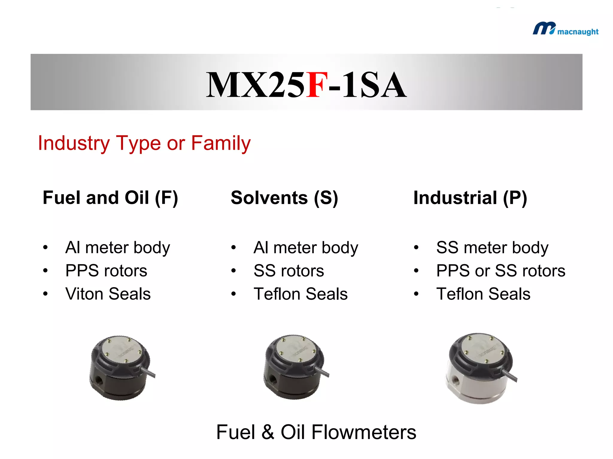
flow measurement
Presentation Overview
1.Flow meter technology
2.Positive Displacement - Principle of operation.
3.Ideal applications
4.What's new
5.Introducing the new generation MX series Flowmeters.
Flowmeter Technologies
There are 4 general groupings by which a flow meter can
be categorised, according to the technology adopted.

 Velocity
 Inferential
 Mass
 Volumetric
Flow Measurement Technology
Volumetric Flowmeter
‘Directly measure the total volume of the fluid passing
through the pipe’







Oval Gear
Rotary
Nutating Disc
Bi-Rotor
Spur Gear
Oscillating Piston
Flow Measurement Technology
Typical Applications
Volumetric
•
•
•
•
•

Batching
Dispensing
Dosing
Fuel Consumption
Applications requiring accurate
totals

Flow Measurement Technology
Positive Displacement
Flowmeter
Principle of Operation
A precision engineered
measuring chamber
houses a pair of oval rotors
which rotate during flow
conditions

Meter Construction
Principle of Operation
As the Rotors turn they sweep a measured volume of
liquid through the measuring chamber
Measured Volume

Measuring Chamber
Principle of Operation
• Each of the Rotors are
fitted with magnets on the
top face.
• As the Rotor turns the
magnet activates a switch
which is fixed to a Printed
Circuit Board (PCB)
• This in turn generates a
Pulse Output
Principle of Operation
Our Sensor Boards (PCB)
incorporate two types of switches.
 Reed Switch
Mechanical Switch

 Hall Effect Switch
Solid State

Electronics – Printed Circuit Board
Calculating Flow Rate
• The K- Factor is … ‘The number of Sensor Pulses per Unit of
Measure’ (Litre or US gallon)
• Each meter is assigned an individual K-Factor calculated during
our calibration checks
Example ….
 A meter has an independent K-Factor 36 (= 36 pulses per
litre)
 Each pulse generated by the meter is the equivalent to
1 Ltr ÷ 36 = 27.8 ml
 An Electronic device (Signal Conditioner) is used to convert
these pulse outputs to Flow Rate and Total Flow

K-Factor
The Benefits associated
with a PD Meter
Technical Specifications
 Accuracy
• +/- 0.5%

(500ml in every 100 litres)

 Repeatability
• 0.03%

(30ml in every 100 litres)

Flow Measurement Technology
Installation and Commissioning
 Reliable
 Robust
 Easily maintained on site
 No pipe conditioning required
 Suitable for variations in medium
(e.g. viscosity, concentrations, etc. )

Flow Measurement Technology
Suitable Applications
Ideal Applications
Dispensing
 Refuelling
 Vehicle Servicing
 Drum Filling
 Chemical Packaging

Positive Displacement Flow Meters
Servicing and Transfer
Diesel Service Truck
Ideal Applications
Batching
 Chemical Dilution and Packaging
 Food / Baking
 Animal Feed

Flow Measurement Technology
Automatic Batching
Automatic Filling System
Multiple Drum Filling
Portable Batching System
New application – AdBlue metering
Fuel Consumption System
Recirculation Fuel System - Meter Installation - Schematic
Receiving
Instrument

Master
Fuel
Filter

Fi
lte
r

Fuel Tank

NonReturn
Valve

Fuel
Consumption
calculated as
Meter P1 Meter P2

Meter
P1

Engine

Meter
P2
Ideal Applications
High Viscosity






Fuels and Lubricants
Paints and Coatings
Adhesives
Printing Ink
Cleaning Chemicals

Positive Displacement Flow Meters
Agricultural Dispensing
What’s New?
The new MX Flowmeter series
 Pulser range only
 Manufactured from solid Billet
(St.St and Aluminium)
 Increased Temp (150oC)
 Pressure Ratings (2000psi)
 Anodised Aluminium body
 Choice of 9 interchangeable
Pulse Output or Display
Modules.
M-Lock™ mounting system
We have developed a new ¼”
turn (Bayonet fitting) mounting
system for our Pulse Output and
Display modules.
Approved for Hazardous Areas
 Intrinsically Safe (Ex ia)
 Flameproof (Exd)
 Approved ATEX,
 Approved IECEx pending
*Note: Ex option only available with the
Industrial Flowmeter Series
Online Resources
Macnaught has developed a comprehensive set of
web based resources in order to support customers
throughout the entire process of selecting, applying
and maintaining the MX Flow meter range.

http://www.macnaught.com.au/mx_resources/index.html
Interactive Web Tools
 Automated Flowmeter Selection Tool
 Specifications Tool
 Conversion Tool (coming soon)
Online Information
General web based resources
Quick Reference Guides
General Specifications
3D Drawings
Instruction Manuals
Service Videos
Brochures
Marketing Resources
MX Demo Kit
We have developed an MX
Demonstration Kit to compliment
the launch of the MX series.
table top exhibitions
in-house display
staff training
direct sales tool.
Overview of the new
generation MX Series
Flowmeter Range overview
 The range consists of over
1,000 flowmeter models.
 Process Connection sizes
range from ¼” to 4”
(6mm – 100mm)
 Flow Rates range from
0.0083 – 1200 l/min
 Stainless Steel and Alum.
Range Segmentation
Application Based Focused on Ideal applications
1. Fuel and Oil
2. Solvent
3. Industrial

All Inclusive PART number
1. Includes Flange Styles
2. Includes displays
MX part numbering
convention
MX25F-1SA
Breakdown of the part numbering system

Part Number
MX25F-1SA
Breakdown of the part numbering system
MX … Flowmeter Series

Part Number
MX25F-1SA
Breakdown of the part numbering system
MX … Flowmeter Series
25 … Size and Flow Range

Part Number
MX25F-1SA
F
Breakdown of the part numbering system
MX … Flowmeter Series
25 … Size and Flow Range
F

… Industry Type or Family

Part Number
MX25F-1SA
Breakdown of the part numbering system
MX … Flowmeter Series
25 … Size and Flow Range
F … Industry Type or Family
1

… Port style (process connection)

Part Number
MX25F-1SA
Breakdown of the part numbering system
MX … Flowmeter Series
25 … Size and Flow Range
F … Industry Type or Family
1 … Port style (process connection)
S

… Rotor Type

Part Number
MX25F-1SA
Breakdown of the part numbering system
MX … Flowmeter Series
25 … Size and Flow Range
F … Industry Type or Family
1 … Port style (process connection)
S … Rotor Type
A

… Display or Pulser Output Type
Part Number
MX25F-1SA
Size and Flow Range
Model No. (mm)

Size

Flow Range

MX06

¼”

0.5 – 100 l/hr

MX09

¼”

15 – 500 l/hr

MX12

½”

2 – 30 l/min

MX19

¾”

3 – 80 l/min

MX25

1”

6 – 120 l/min

MX40

1 ½”

10 – 250 l/min

MX50

2”

15 – 500 l/min

MX75

3”

20 – 750 l/min

MX100

4”

120 – 1200 l/min
MX25F-1SA
Industry Type or Family
Fuel and Oil (F)

Solvents (S)

Industrial (P)

• Al meter body
• PPS rotors
• Viton Seals

•
•
•

•
•
•

Al meter body
SS rotors
Teflon Seals

Fuel & Oil Flowmeters

SS meter body
PPS or SS rotors
Teflon Seals
MX25F-1SA
Port Style (process connection)
1.
2.
3.
4.
5.

BSP (Rp)
NPT
ANSI 150lb
JIS 10K
DIN PN16
MX25F-1SA
Rotor Type
Fuel and Oil series
S = PPS Rotors
Solvent series
S = Models MX06 - MX025
Models MX40 – MX100

Stainless Steel Rotors
Aluminium Rotors

Industrial series
S = PPS
V = High Viscosity Stainless Steel Rotors
T = High Temp Stainless Steel
MX25F-1SA
Display or Pulser Output Modules
A
B
C
D
E
F
G
H
T

Standard Pulse
Intrinsically Safe (Ex ia)
Flameproof (Ex d)
PR (12mm LCD)
PRA (12mm LCD with outputs)
ER (17mm LCD)
ERA (17mm LCD with outputs)
ERB (17mm LCD Batch controller)
High Temp (max 150oC)
Pulser Output and
Display Modules
Type A

Compact
Compact
•
•
•
•
•

Polypropylene Housing
IP 67
Pulser Output
1x Reed switch
1x Hall Effect (NPN)
Type B

Approved Ex ia
Intrinsically Safe
•
•
•
•
•
•
•
•

Stainless Steel
Pulser Output
NPN Open Collector
Approved Ex ia
ATEX
FM
CSA
IECEx pending

*Note: Ex option only available with the Industrial Flowmeter Series
Type C

Approved Exd
Flameproof
•
•
•
•
•
•

Stainless Steel
Pulser Output
NPN Open Collector
Approved Exd
ATEX
IECEx pending

*Note: Ex option only available with the Industrial Flowmeter Series
Type D

PR Digital Display
Display
•
•
•
•
•
•
•

Meter Mount or Wall Mount
Polypropylene Housing IP67
7 Digit – 12mm upper
7 Digit – 8mm lower
Total Resettable
Flow Rate
Accumulated Total (non-resettable)
Type E

PRA Digital Display
Display
•
•
•
•
•
•
•

Meter Mount or Wall Mount
Polypropylene Housing IP67
7 Digit – 12mm upper
7 Digit – 8mm lower
Total Resettable
Flow Rate
Accumulated Total (non-resettable)

Outputs
•
•
•

4-20mA (passive)
Scaled Pulse Output
Hi/Lo Flow Alarm
Type F

ER Digital Display
Display
•
•
•
•
•
•
•

Meter Mount or Remote Mount
Aluminium housing IP 67
7 Digit – 17mm upper
7 Digit – 8mm lower
Total Resettable
Flow Rate
Accumulated Total (non-resettable)
Type G

ERA Digital Display
Display
•
•
•
•
•
•
•

Meter Mount or Remote Mount
Aluminium housing IP 67
7 Digit – 17mm upper
7 Digit – 8mm lower
Total Resettable
Flow Rate
Accumulated Total (non-resettable)

Output
• 4-20mA (passive)
• Scaled Pulse
Type H

ERB Batch Controller
Display
•
•
•
•
•
•
•

Meter Mount or Remote Mount
Aluminium housing IP 67
7 Digit – 17mm upper
7 Digit – 8mm lower
Total Resettable
Flow Rate
Accumulated Total (non-resettable)

Output
• 4-20mA (passive)
• Scaled Pulse
Type T

High Temperature
Intrinsically Safe
•
•
•
•

Stainless Steel
Pulser Output
NPN Open Collector
Max temp 150oC
ERS Digital Register
Summation / Differential
Display
•
•
•
•
•
•
•

Remote Mount only
Aluminium housing IP 67
7 Digit – 17mm upper
7 Digit – 8mm lower
2 Flowmeter inputs
Calculates differential
Sums

Output
• Transistor
Accessories
Flanged Process Connections
• Flanges are now screwed into the Meter body
• Available in ANSI, DIN, JIS
Wall Mount Adaptors
• Aluminium wall mount adaptors available for models MX06-25
Strainers / Air Eliminators
• A variety of SS Y-Strainers, and Air Eliminator/Strainer
combinations are available.
Turck Cables
•2mtr cables to suit Ex ia and High Temp Pulser switches
End Presentation

Distributor presentation mx

  • 1.
  • 2.
    Presentation Overview 1.Flow metertechnology 2.Positive Displacement - Principle of operation. 3.Ideal applications 4.What's new 5.Introducing the new generation MX series Flowmeters.
  • 3.
    Flowmeter Technologies There are4 general groupings by which a flow meter can be categorised, according to the technology adopted.  Velocity  Inferential  Mass  Volumetric Flow Measurement Technology
  • 4.
    Volumetric Flowmeter ‘Directly measurethe total volume of the fluid passing through the pipe’       Oval Gear Rotary Nutating Disc Bi-Rotor Spur Gear Oscillating Piston Flow Measurement Technology
  • 5.
  • 6.
  • 7.
    Principle of Operation Aprecision engineered measuring chamber houses a pair of oval rotors which rotate during flow conditions Meter Construction
  • 8.
    Principle of Operation Asthe Rotors turn they sweep a measured volume of liquid through the measuring chamber Measured Volume Measuring Chamber
  • 9.
    Principle of Operation •Each of the Rotors are fitted with magnets on the top face. • As the Rotor turns the magnet activates a switch which is fixed to a Printed Circuit Board (PCB) • This in turn generates a Pulse Output
  • 10.
    Principle of Operation OurSensor Boards (PCB) incorporate two types of switches.  Reed Switch Mechanical Switch  Hall Effect Switch Solid State Electronics – Printed Circuit Board
  • 11.
    Calculating Flow Rate •The K- Factor is … ‘The number of Sensor Pulses per Unit of Measure’ (Litre or US gallon) • Each meter is assigned an individual K-Factor calculated during our calibration checks Example ….  A meter has an independent K-Factor 36 (= 36 pulses per litre)  Each pulse generated by the meter is the equivalent to 1 Ltr ÷ 36 = 27.8 ml  An Electronic device (Signal Conditioner) is used to convert these pulse outputs to Flow Rate and Total Flow K-Factor
  • 12.
  • 13.
    Technical Specifications  Accuracy •+/- 0.5% (500ml in every 100 litres)  Repeatability • 0.03% (30ml in every 100 litres) Flow Measurement Technology
  • 14.
    Installation and Commissioning Reliable  Robust  Easily maintained on site  No pipe conditioning required  Suitable for variations in medium (e.g. viscosity, concentrations, etc. ) Flow Measurement Technology
  • 15.
  • 16.
    Ideal Applications Dispensing  Refuelling Vehicle Servicing  Drum Filling  Chemical Packaging Positive Displacement Flow Meters
  • 17.
  • 18.
  • 19.
  • 20.
  • 21.
    Ideal Applications Batching  ChemicalDilution and Packaging  Food / Baking  Animal Feed Flow Measurement Technology
  • 22.
  • 23.
  • 24.
  • 25.
  • 26.
    New application –AdBlue metering
  • 27.
    Fuel Consumption System RecirculationFuel System - Meter Installation - Schematic Receiving Instrument Master Fuel Filter Fi lte r Fuel Tank NonReturn Valve Fuel Consumption calculated as Meter P1 Meter P2 Meter P1 Engine Meter P2
  • 28.
    Ideal Applications High Viscosity      Fuelsand Lubricants Paints and Coatings Adhesives Printing Ink Cleaning Chemicals Positive Displacement Flow Meters
  • 29.
  • 30.
  • 31.
    The new MXFlowmeter series  Pulser range only  Manufactured from solid Billet (St.St and Aluminium)  Increased Temp (150oC)  Pressure Ratings (2000psi)  Anodised Aluminium body  Choice of 9 interchangeable Pulse Output or Display Modules.
  • 32.
    M-Lock™ mounting system Wehave developed a new ¼” turn (Bayonet fitting) mounting system for our Pulse Output and Display modules.
  • 33.
    Approved for HazardousAreas  Intrinsically Safe (Ex ia)  Flameproof (Exd)  Approved ATEX,  Approved IECEx pending *Note: Ex option only available with the Industrial Flowmeter Series
  • 34.
    Online Resources Macnaught hasdeveloped a comprehensive set of web based resources in order to support customers throughout the entire process of selecting, applying and maintaining the MX Flow meter range. http://www.macnaught.com.au/mx_resources/index.html
  • 35.
    Interactive Web Tools Automated Flowmeter Selection Tool  Specifications Tool  Conversion Tool (coming soon)
  • 36.
    Online Information General webbased resources Quick Reference Guides General Specifications 3D Drawings Instruction Manuals Service Videos Brochures
  • 37.
    Marketing Resources MX DemoKit We have developed an MX Demonstration Kit to compliment the launch of the MX series. table top exhibitions in-house display staff training direct sales tool.
  • 38.
    Overview of thenew generation MX Series
  • 39.
    Flowmeter Range overview The range consists of over 1,000 flowmeter models.  Process Connection sizes range from ¼” to 4” (6mm – 100mm)  Flow Rates range from 0.0083 – 1200 l/min  Stainless Steel and Alum.
  • 40.
    Range Segmentation Application BasedFocused on Ideal applications 1. Fuel and Oil 2. Solvent 3. Industrial All Inclusive PART number 1. Includes Flange Styles 2. Includes displays
  • 41.
  • 42.
    MX25F-1SA Breakdown of thepart numbering system Part Number
  • 43.
    MX25F-1SA Breakdown of thepart numbering system MX … Flowmeter Series Part Number
  • 44.
    MX25F-1SA Breakdown of thepart numbering system MX … Flowmeter Series 25 … Size and Flow Range Part Number
  • 45.
    MX25F-1SA F Breakdown of thepart numbering system MX … Flowmeter Series 25 … Size and Flow Range F … Industry Type or Family Part Number
  • 46.
    MX25F-1SA Breakdown of thepart numbering system MX … Flowmeter Series 25 … Size and Flow Range F … Industry Type or Family 1 … Port style (process connection) Part Number
  • 47.
    MX25F-1SA Breakdown of thepart numbering system MX … Flowmeter Series 25 … Size and Flow Range F … Industry Type or Family 1 … Port style (process connection) S … Rotor Type Part Number
  • 48.
    MX25F-1SA Breakdown of thepart numbering system MX … Flowmeter Series 25 … Size and Flow Range F … Industry Type or Family 1 … Port style (process connection) S … Rotor Type A … Display or Pulser Output Type Part Number
  • 49.
    MX25F-1SA Size and FlowRange Model No. (mm) Size Flow Range MX06 ¼” 0.5 – 100 l/hr MX09 ¼” 15 – 500 l/hr MX12 ½” 2 – 30 l/min MX19 ¾” 3 – 80 l/min MX25 1” 6 – 120 l/min MX40 1 ½” 10 – 250 l/min MX50 2” 15 – 500 l/min MX75 3” 20 – 750 l/min MX100 4” 120 – 1200 l/min
  • 50.
    MX25F-1SA Industry Type orFamily Fuel and Oil (F) Solvents (S) Industrial (P) • Al meter body • PPS rotors • Viton Seals • • • • • • Al meter body SS rotors Teflon Seals Fuel & Oil Flowmeters SS meter body PPS or SS rotors Teflon Seals
  • 51.
    MX25F-1SA Port Style (processconnection) 1. 2. 3. 4. 5. BSP (Rp) NPT ANSI 150lb JIS 10K DIN PN16
  • 52.
    MX25F-1SA Rotor Type Fuel andOil series S = PPS Rotors Solvent series S = Models MX06 - MX025 Models MX40 – MX100 Stainless Steel Rotors Aluminium Rotors Industrial series S = PPS V = High Viscosity Stainless Steel Rotors T = High Temp Stainless Steel
  • 53.
    MX25F-1SA Display or PulserOutput Modules A B C D E F G H T Standard Pulse Intrinsically Safe (Ex ia) Flameproof (Ex d) PR (12mm LCD) PRA (12mm LCD with outputs) ER (17mm LCD) ERA (17mm LCD with outputs) ERB (17mm LCD Batch controller) High Temp (max 150oC)
  • 54.
  • 55.
    Type A Compact Compact • • • • • Polypropylene Housing IP67 Pulser Output 1x Reed switch 1x Hall Effect (NPN)
  • 56.
    Type B Approved Exia Intrinsically Safe • • • • • • • • Stainless Steel Pulser Output NPN Open Collector Approved Ex ia ATEX FM CSA IECEx pending *Note: Ex option only available with the Industrial Flowmeter Series
  • 57.
    Type C Approved Exd Flameproof • • • • • • StainlessSteel Pulser Output NPN Open Collector Approved Exd ATEX IECEx pending *Note: Ex option only available with the Industrial Flowmeter Series
  • 58.
    Type D PR DigitalDisplay Display • • • • • • • Meter Mount or Wall Mount Polypropylene Housing IP67 7 Digit – 12mm upper 7 Digit – 8mm lower Total Resettable Flow Rate Accumulated Total (non-resettable)
  • 59.
    Type E PRA DigitalDisplay Display • • • • • • • Meter Mount or Wall Mount Polypropylene Housing IP67 7 Digit – 12mm upper 7 Digit – 8mm lower Total Resettable Flow Rate Accumulated Total (non-resettable) Outputs • • • 4-20mA (passive) Scaled Pulse Output Hi/Lo Flow Alarm
  • 60.
    Type F ER DigitalDisplay Display • • • • • • • Meter Mount or Remote Mount Aluminium housing IP 67 7 Digit – 17mm upper 7 Digit – 8mm lower Total Resettable Flow Rate Accumulated Total (non-resettable)
  • 61.
    Type G ERA DigitalDisplay Display • • • • • • • Meter Mount or Remote Mount Aluminium housing IP 67 7 Digit – 17mm upper 7 Digit – 8mm lower Total Resettable Flow Rate Accumulated Total (non-resettable) Output • 4-20mA (passive) • Scaled Pulse
  • 62.
    Type H ERB BatchController Display • • • • • • • Meter Mount or Remote Mount Aluminium housing IP 67 7 Digit – 17mm upper 7 Digit – 8mm lower Total Resettable Flow Rate Accumulated Total (non-resettable) Output • 4-20mA (passive) • Scaled Pulse
  • 63.
    Type T High Temperature IntrinsicallySafe • • • • Stainless Steel Pulser Output NPN Open Collector Max temp 150oC
  • 64.
    ERS Digital Register Summation/ Differential Display • • • • • • • Remote Mount only Aluminium housing IP 67 7 Digit – 17mm upper 7 Digit – 8mm lower 2 Flowmeter inputs Calculates differential Sums Output • Transistor
  • 65.
    Accessories Flanged Process Connections •Flanges are now screwed into the Meter body • Available in ANSI, DIN, JIS Wall Mount Adaptors • Aluminium wall mount adaptors available for models MX06-25 Strainers / Air Eliminators • A variety of SS Y-Strainers, and Air Eliminator/Strainer combinations are available. Turck Cables •2mtr cables to suit Ex ia and High Temp Pulser switches
  • 66.