Downloaded 909 times
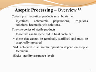
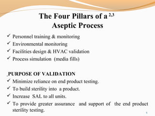
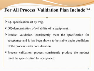
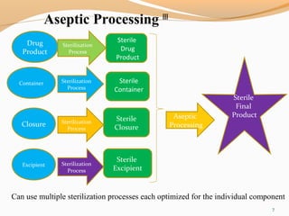
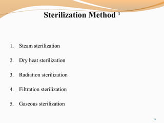
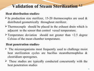
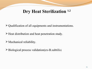
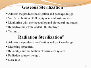
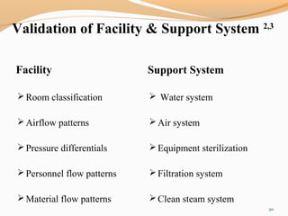
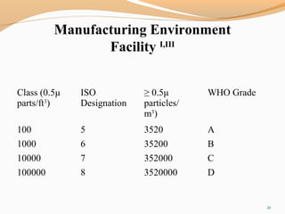
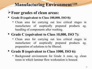
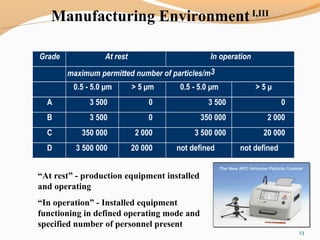


The document outlines the principles and methods of sterile process validation in the pharmaceutical industry, emphasizing the importance of aseptic processing and validation to ensure sterility. It discusses key elements such as personnel training, environmental monitoring, facilities design, and various sterilization methods, including steam and filtration. Additionally, the document highlights the validation steps, including the development of testing protocols and the significance of maintaining strict cleanliness and control in manufacturing environments.


](https://cdn.slidesharecdn.com/ss_thumbnails/sediaansterilcompatibilitymode1-150318083756-conversion-gate01-thumbnail.jpg?width=640&height=640&fit=bounds)


![CASE_PRESENTATION_ON_subdural_hematoma(SDH)[1 FINAL PPT]-1.pptx](https://cdn.slidesharecdn.com/ss_thumbnails/casepresentationonsubduralhematomasdh1finalppt-1-260129172522-d405d375-thumbnail.jpg?width=640&height=640&fit=bounds)


