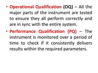
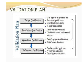
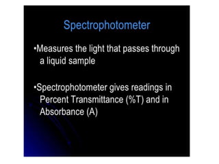
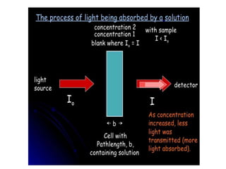
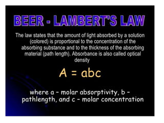
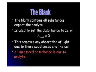
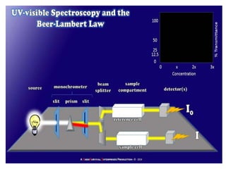
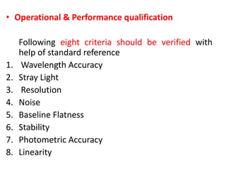
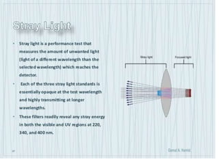
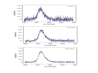
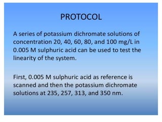
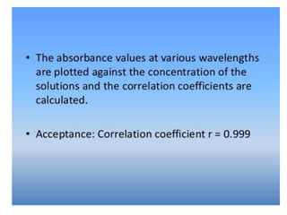
2. Qualification
• When validation approach is related to a
machine or equipment, rather than Validation,
this is referred to as Qualification.
• Qualification is described as the action of
proving that any premises, systems and items
of equipment work correctly and actually lead
to the expected results.
• It is the process used to establish confidence
that the equipment is capable of consistently
operating within established limits and
tolerances
3. • Qualification is often a part (initial state) of
validation but the individual qualification
steps alone do not constitute process
validation
• Validation Process
• Instrument validation begins with a
validation master plan that defines the steps
in each process. Traditionally, these steps can
be categorized into 4 separate qualification
categories (DQ IQ OQ PQ ), which include:
4. • Design Qualification (DQ) – The first step is to
demonstrate whether the proposed design of
the instrument can cope with the functional
requirements of the end user. A proposed
design must satisfy the DQ before
construction and procurement of parts.
• Installation Qualification (IQ) – The
instrument, with all its components and
documentation, is placed correctly and
checked for performance according to the
requirements.
5. • Operational Qualification (OQ) – All the
major parts of the instrument are tested
to ensure they all perform correctly and
are in sync with the entire system.
• Performance Qualification (PQ) – The
instrument is monitored over a period of
time to check if it consistently delivers
results within the required parameters.
15. purpose
• The purpose of qualification is to provide test
methodologies and acceptance criteria to ensure
that the instrument is suitable for its intended
use and that it will continue to function properly
over extended time periods as part of PQ. A UV-
Vis spectrophotometer must be qualified for both
wavelength (x-axis) and photometric (y-axis, or
signal axis) accuracy and precision, and the
fundamental parameters of stray light and
resolution must be established. OQ is carried out
across the operational ranges required within the
laboratory for both the absorbance and
wavelength scales.
16.
17. Installation Qualification
• The IQ requirements provide
evidence that the hardware and
software are properly installed in the
desired location.
18. • Operational & Performance qualification
Following eight criteria should be verified with
help of standard reference
1. Wavelength Accuracy
2. Stray Light
3. Resolution
4. Noise
5. Baseline Flatness
6. Stability
7. Photometric Accuracy
8. Linearity
19. Wavelength Accuracy
• Wavelength accuracy is defined as the
deviation of the wavelength reading at an
absorption band from the known wavelength
of the band.
• The wavelength deviation can cause
significant errors in the qualitative and
quantitative results of the UV–Vis
measurement.
20.
21. Protocol for Checking Wavelength
Accuracy
• Wavelength accuracy verification is checked by
measuring a known wave-length reference
standard with well-characterized absorption or
emission peaks and comparing the recorded
wavelength of the peak(s) against the value (s)
listed in the certificate of that reference standard.
There are many standards that are commonly
used to verify the wavelength accuracy of a
spectrophotometer
22. Control of wavelengths
• Verify the wavelength scale using the
absorption maxima of holmium perchlorate
solution , the line of a hydrogen or deuterium
discharge lamp or the lines of a mercury vapor
arc shown below.
• 241.15 nm (Ho) 404.66 nm (Hg) 253.7 nm (Hg)
435.83 nm (Hg) 287.15 nm (Ho) 486.0 nm (Db)
302.25 nm (Hg) 486.1 nm (Hb) 313.16 nm (Hg)
536.3 nm (Ho) 334.15 nm (Hg) 546.07 nm (Hg)
361.5 nm (Ho) 576.96 nm (Hg) 365.48 nm (Hg)
579.07 nm (Hg)
23. • Spectra of some commonly used wavelength
standards such as a deuterium lamp, mercury
vapour lamp, holmium oxide filter, and holmium
oxide solution (4% holmium oxide in 10%
perchloric acid in a 1-cm cell ).
• • Acceptance. ±1 nm in the UV range (200 to 380
nm) and ±3 nm in the visible range (380 to 800
nm). Three repeated scans of the same peak
should be within ±0.5nm .
24. Stray Light
• Stray Light Stray light is defined as the detected
light of any wavelength that is outside the
bandwidth of the wavelength selected.
• The causes for stray light are scattering, or poor
instrument design.
• Stray light causes a decrease in absorbance and
reduces the linear range of the instrument.
• High-absorbance measurements are affected
more severely by stray light .
25.
26. PROTOCOL
• For the stray light test, various cut-off filters or solutions
can be used to estimate the stray light contribution,
depending on the wavelengths is used.
• Scan the stray light testing solution in a 1-cm cell using air
as the reference.
• The absorption of a solution of potassium chloride R (12
g/l) between 220 nm and 200 nm in a light path of 1 cm
must rise suddenly and at a wavelength of 198 nm must be
greater than 2, measured against water R as a
compensation liquid