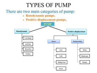
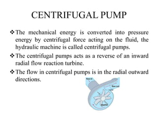
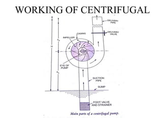
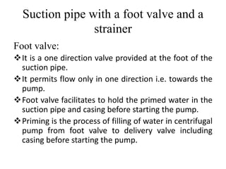
PUMP
The hydraulic machines which convert the
mechanical energy into hydraulic energy are
called the pumps.
The hydraulic energy is in the form of
pressure energy.
Flow is normally from high pressure to low
pressure.
Flow from a low level to a higher level.
TYPES OF PUMP
Rotodynamic pump:
Increase in energy level is due to combination of
Centrifugal energy, pressure energy and kinetic
energy.
Positive displacement pump:
Liquid is sucked and then displaced due to the thrust
Exerted on it by a moving member that results in the
lifting of liquid to a desired height.
TYPES OF PUMP
There are two main categories of pump:
 Rotodynamic pumps.
 Positive displacement pumps.
Diaphragm
Piston
Plunger
Reciprocating
Rotary
Mixed flow
Gear
Lobe
Sliding Vane
Screw
Axial flow
Centrifugal
Rotodynamic
Turbine
Positive displacement
PUMP
CENTRIFUGAL PUMP
The mechanical energy is converted into pressure
energy by centrifugal force acting on the fluid, the
hydraulic machine is called centrifugal pumps.
The centrifugal pumps acts as a reverse of an inward
radial flow reaction turbine.
The flow in centrifugal pumps is in the radial outward
directions.
Classification of Centrifugal Pumps
Centrifugal pumps may be classified according to,
1.Working head
2.Specific speed
3.Type of casing
4.Direction of flow of water
5.Number of entrances to the impeller
6.Disposition of shaft
7.Number of stage
CENTRIFUGAL PUMP
CLASSIFICATION OF CENTRIFUGAL PUMP
WORKING OF CENTRIFUGAL
PUMP
MAIN PARTS OF CENTRIFUGAL
PUMP
1. Impeller.
2. Casing.
3. Suction pipe with a foot valve and a strainer.
4. Delivery pipe.
IMPELLER
The rotating part of a centrifugal pump is called
impeller.
It consists of a series of backward curved vanes.
The impeller is mounted on a shaft which is
connected to the shaft of an electrical motor.
TYPES OF IMPELLER
CASING
It is an airtight chamber, which accommodates the
rotating impeller.
The area of flow of the casing gradually increases in
the direction of flow of water to convert kinematic
energy into pressure energy.
The following three types of casing are commonly
adopted:
1.Volute casing.
2.Vortex casing.
3.Diffuser (or) casing with guide blades
Volute casing
Such type of casing is of spiral form, and has a
sectional area, which increase uniformly from the
tongue to the delivery pipe.
more area is provided to accommodate increased
quantity of water as the water moves towards the
delivery pipe.
Vortex casing
In a vortex chamber, a uniformly increasing
area is provided between the impeller outer
periphery and the volute casing water, on
leaving the impeller becomes free to adopt its
path.
Diffuser (or) casing with guide
blades
In a diffuser Pump, the guide vanes are arranged at
the outlet of the impeller vanes. Water enters the
guide without shock.
As the guide vanes are of enlarging cros-sectional
area, the velocity of water decreased and pressure
increases Since the vanes provide better guidance to
flow, eddy losses are reduced which increases the
efficiency.
Suction pipe with a foot valve and a
strainer
Suction pipe:
It is the pipe through which water is lifted from the
sump to the pump level.
Thus the pipe has its lower end dipped in the sump
water and the upper end is connected to the eye or the
inlet of the pump.
At the lower end, a strainer and a foot-valve are also
fitted.
Strainer:
 It is a screen provided at the foot of the suction
pipe, it would not allow entrance of the solid matters
into the suction pipe which otherwise may damage
the pump.
Suction pipe with a foot valve and a
strainer
Foot valve:
It is a one direction valve provided at the foot of the
suction pipe.
It permits flow only in one direction i.e. towards the
pump.
Foot valve facilitates to hold the primed water in the
suction pipe and casing before starting the pump.
Priming is the process of filling of water in centrifugal
pump from foot valve to delivery valve including
casing before starting the pump.
Delivery pipe
• Delivery pipe is used for delivery of liquid. One end
connected to the outlet of the pump while the other
delivers the water at the required height to the
delivery tank.
WORKING OF CENTRIFUGAL PUMP
Works on the principle that when a certain mass of
fluid is rotated by an external source, it is thrown
away from the central axis of rotation and a
centrifugal head is impressed which enables it to rise
to a higher level.
In order to start a pump, it has to be filled with water
so that the centrifugal head developed is sufficient to
lift the water from the sump. The process is called
priming.
Pump is started by electric motor to rotate the
impeller.
Rotation of impeller in casing full of water produces
forced vortex which creates a centrifugal head on the
liquid.
The delivery valve is opened as the centrifugal head
is impressed.
This results in the flow of liquid in an outward
radial direction with high velocity and pressure
enabling the liquid to enter the delivery pipe.
Partial vacuum is created at the centre of the
impeller which makes the sump water at
atmospheric pressure to rush through the pipe.
Delivery of water from sump to delivery pipe
continues so long as the pump is on.

Centrifugal pump

  • 1.
    PUMP The hydraulic machineswhich convert the mechanical energy into hydraulic energy are called the pumps. The hydraulic energy is in the form of pressure energy. Flow is normally from high pressure to low pressure. Flow from a low level to a higher level.
  • 2.
    TYPES OF PUMP Rotodynamicpump: Increase in energy level is due to combination of Centrifugal energy, pressure energy and kinetic energy. Positive displacement pump: Liquid is sucked and then displaced due to the thrust Exerted on it by a moving member that results in the lifting of liquid to a desired height.
  • 3.
    TYPES OF PUMP Thereare two main categories of pump:  Rotodynamic pumps.  Positive displacement pumps. Diaphragm Piston Plunger Reciprocating Rotary Mixed flow Gear Lobe Sliding Vane Screw Axial flow Centrifugal Rotodynamic Turbine Positive displacement PUMP
  • 4.
    CENTRIFUGAL PUMP The mechanicalenergy is converted into pressure energy by centrifugal force acting on the fluid, the hydraulic machine is called centrifugal pumps. The centrifugal pumps acts as a reverse of an inward radial flow reaction turbine. The flow in centrifugal pumps is in the radial outward directions.
  • 5.
    Classification of CentrifugalPumps Centrifugal pumps may be classified according to, 1.Working head 2.Specific speed 3.Type of casing 4.Direction of flow of water 5.Number of entrances to the impeller 6.Disposition of shaft 7.Number of stage
  • 6.
  • 7.
  • 8.
    MAIN PARTS OFCENTRIFUGAL PUMP 1. Impeller. 2. Casing. 3. Suction pipe with a foot valve and a strainer. 4. Delivery pipe.
  • 9.
    IMPELLER The rotating partof a centrifugal pump is called impeller. It consists of a series of backward curved vanes. The impeller is mounted on a shaft which is connected to the shaft of an electrical motor.
  • 10.
  • 11.
    CASING It is anairtight chamber, which accommodates the rotating impeller. The area of flow of the casing gradually increases in the direction of flow of water to convert kinematic energy into pressure energy. The following three types of casing are commonly adopted: 1.Volute casing. 2.Vortex casing. 3.Diffuser (or) casing with guide blades
  • 12.
    Volute casing Such typeof casing is of spiral form, and has a sectional area, which increase uniformly from the tongue to the delivery pipe. more area is provided to accommodate increased quantity of water as the water moves towards the delivery pipe.
  • 13.
    Vortex casing In avortex chamber, a uniformly increasing area is provided between the impeller outer periphery and the volute casing water, on leaving the impeller becomes free to adopt its path.
  • 14.
    Diffuser (or) casingwith guide blades In a diffuser Pump, the guide vanes are arranged at the outlet of the impeller vanes. Water enters the guide without shock. As the guide vanes are of enlarging cros-sectional area, the velocity of water decreased and pressure increases Since the vanes provide better guidance to flow, eddy losses are reduced which increases the efficiency.
  • 16.
    Suction pipe witha foot valve and a strainer Suction pipe: It is the pipe through which water is lifted from the sump to the pump level. Thus the pipe has its lower end dipped in the sump water and the upper end is connected to the eye or the inlet of the pump. At the lower end, a strainer and a foot-valve are also fitted. Strainer:  It is a screen provided at the foot of the suction pipe, it would not allow entrance of the solid matters into the suction pipe which otherwise may damage the pump.
  • 17.
    Suction pipe witha foot valve and a strainer Foot valve: It is a one direction valve provided at the foot of the suction pipe. It permits flow only in one direction i.e. towards the pump. Foot valve facilitates to hold the primed water in the suction pipe and casing before starting the pump. Priming is the process of filling of water in centrifugal pump from foot valve to delivery valve including casing before starting the pump.
  • 18.
    Delivery pipe • Deliverypipe is used for delivery of liquid. One end connected to the outlet of the pump while the other delivers the water at the required height to the delivery tank.
  • 19.
    WORKING OF CENTRIFUGALPUMP Works on the principle that when a certain mass of fluid is rotated by an external source, it is thrown away from the central axis of rotation and a centrifugal head is impressed which enables it to rise to a higher level. In order to start a pump, it has to be filled with water so that the centrifugal head developed is sufficient to lift the water from the sump. The process is called priming. Pump is started by electric motor to rotate the impeller. Rotation of impeller in casing full of water produces forced vortex which creates a centrifugal head on the liquid. The delivery valve is opened as the centrifugal head is impressed.
  • 20.
    This results inthe flow of liquid in an outward radial direction with high velocity and pressure enabling the liquid to enter the delivery pipe. Partial vacuum is created at the centre of the impeller which makes the sump water at atmospheric pressure to rush through the pipe. Delivery of water from sump to delivery pipe continues so long as the pump is on.