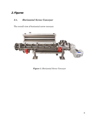
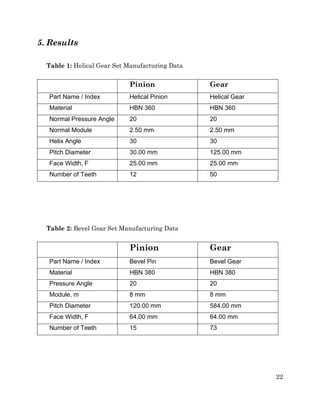
MECHANICAL ENGINEERING DEPARTMENT
ME 308
MACHINE ELEMENTS II
Spring 2018
Project Title : Gearbox Design and Bearing Selection
Project Group : 72
Prepared by : Samet Baykul
Date Submitted : 8.05.2019
Used Data Set : 2
2
ii
I hereby declare that all information in this document has been obtained and
presented in accordance with academic rules and ethical conduct. I also
declare that, as require by these rules and conduct, I have fully cited and
referenced all material and results that are not original to this work.
Name, Last Name : Samet Baykul
Signature :
iii
Table of Contents
1. Introduction
2. Figures
3. Design Calculations
3.1. Helical Gears Design
3.2. Bevel Gears Design
3.3. Bearing Design
4. Other Considerations
4.1. Mounting of Shaft 1
4.2. Lubrication of Gearbox
5. Results
6. Discussion
References
5
6
7
7
12
14
20
20
21
22
23
iv
5
1. Introduction
In this project, a suitable gearbox is designed, and bearings are selected for the given
prime mover in a screw conveyor machine. Screw conveyors are used for granular material
transporting applications such as wheat. The granular medium can be transported
efficiently to any desired position, ie. horizontal, vertical or sloped position. The
mechanism illustrated in the Figure 1, a horizontal conveyor machine.
During design phase, AGMA and ISO standards are used in order to calculate required
dimensions, orientations and gear types. Transmitted power, and applied forces are
calculated by using geometric relations.
Bevel gears and helical gears attached to shafts transmit power from the prime mover
to the machine. The shafts are supported by tapered roller bearings and deep groove ball
bearings. The gearbox reduces the output shaft speed relative to the input shaft speed.
This study allows me to apply my knowledge from the ME308 course and knowledge
from previous years to real life problems. During the calculations, ME308 class notes,
catalogues, and Shigley’s Mechanical Engineering Design textbook were utilized.
6
2.Figures
2.1. Horizontal Screw Conveyor
The overall view of horizontal screw conveyor.
Figure 1. Horizontal Screw Conveyor
7
3.Design Calculations
3.1. Helical Gears Design
3.1.1. Material Properties
• Grade 1 Steel
• Through Hardened
• FD involute tooth profiles are uncrowned - Straddle mounted
• Temperature is 85 degree Celsius
3.1.2. Given Information
3.1.3. Calculations
8
9
10
11
Since contact stress is higher than the bending stress, pinion and gear are more
critical for surface failure. So, our mn value becomes 2.5 according to table of
recommended module value.
Module = 2.5mm
No interference.
12
3.2. Bevel Gears Design
13
Module = 8
14
3.3. Bearing Design
3.3.1. Shaft 1
FB
y
FA
y
FB
z
FB
x
FA
z
Wr
Wt
Wa
15
3.3.2. Bearing A
Designation of the Bearing A is 160 06
16
3.3.3. Bearing B
Designation of the Bearing B is 160 06
3.3.4. Tapered Roller Bearing Design
17
18
3.3.5. Bearing E
Designation of the Bearing E is 303 02
19
3.3.6. Bearing F
Designation of the Bearing F is 303 02
20
4.Other Considerations
4.1. Mounting of Shaft 1
While mounting ball and roller bearings, selecting the right mounting type is
important. Besides correct tools should be used.
In this project, deep groove ball bearings have been used for shaft 1 and 303 series
tapered roller bearing used for shaft 3. Deep groove ball bearings have numerous
advantages for this project. Deep groove ball bearings are simple, non-separable,
suitable for higher speeds and are robust in operation, requiring little maintenance.
They are the most widely used bearing type, available in many designs, variants and
sizes. Tapered roller bearings have tapered inner and outer ring raceways and tapered
rollers. They are designed to accommodate combined loads or simultaneously acting
radial and axial loads.
Key is a machine element used to connect a rotating machine element to a shaft.
The key prevents relative rotation between the two parts and may enable torque
transmission. Shaft and rotating machine element should have a keyway and key seat.
The whole system is called as a keyed joint.
Seals are purpose of retaining the lubricant within the bearing and to prevent
humidity and impurities. It is very important since if any particle interferes between
shaft and bearing the bearing performance will be affected negatively even if that
particles are too small.
21
4.2. Lubrication of Gearbox
For the helical gears in the gearbox, a proper lubrication system can increase the
heat dissipation rate from the moving parts such as shafts, bearings etc. Lubrication
system also prevents the wear and corrosion on the surfaces of the components inside
the machine.
In this project, oil bath lubrication system is used. In this lubrication system, oil
in the casing which is up to a level that one of the gears (larger one of the gear pair)
is submerged in oil reservoir and lubricating while it is rotating with the mating gear.
In this system, oil level and temperature are important and must be carried out.
Oil level must be optimum that if it is too high there will be excessive agitation and if
it is too low, it cannot cool down the gears. For the temperature problem, we could add
heat sink to carry away the heat more efficiently. In this project, fins seem to be
enough in order to provide required heat dissipation.
22
5. Results
Table 1: Helical Gear Set Manufacturing Data
Pinion Gear
Part Name / Index Helical Pinion Helical Gear
Material HBN 360 HBN 360
Normal Pressure Angle 20 20
Normal Module 2.50 mm 2.50 mm
Helix Angle 30 30
Pitch Diameter 30.00 mm 125.00 mm
Face Width, F 25.00 mm 25.00 mm
Number of Teeth 12 50
Table 2: Bevel Gear Set Manufacturing Data
Pinion Gear
Part Name / Index Bevel Pin Bevel Gear
Material HBN 380 HBN 380
Pressure Angle 20 20
Module, m 8 mm 8 mm
Pitch Diameter 120.00 mm 584.00 mm
Face Width, F 64.00 mm 64.00 mm
Number of Teeth 15 73
23
6. Discussion
In this project, the main task was to design a gearbox that functions as the power
transmission system and to choose suitable bearings for the shafts in the gearbox.
In the design of gearbox, two different gear pair were designed. First one is the
helical gear mesh, it was designed by using the data given in the data set. The
requirements for the helical gear set were met for a certain module that was found
iteratively. The second one, the bevel gear mesh. Similarly, the main parameter that
resolved the gear mesh design was the module as well. In calculation of both of these
gear pairs, AGMA stress equations were utilized with ISO standards.
After the characteristics of the gear pairs were determined, the shafts that these
gear pairs operated on were considered. The calculation of the shaft parameters was
directly related to the selection of bearings on the gearbox.
Throughout this project, the calculations were carried out on Mathcad. In all
calculation section in this document, only the final calculation results were shown
instead of placing all iterations.
As a conclusion, this project was a challenging design task which consist of
different important calculations for cases in real-life.
References
[1] Shiegly’s Mechanical Design, Budynas,R.G., Nisbett, J.K., 10th Edition, 2015,
McGraw Hill
[2] Notes to be used in examinations,
http://courses.me.metu.edu.tr/courses/me308/
[3] Bearing Catalogue, http://courses.me.metu.edu.tr/courses/me308/

Gearbox Design and Bearing Selection

  • 1.
    MECHANICAL ENGINEERING DEPARTMENT ME308 MACHINE ELEMENTS II Spring 2018 Project Title : Gearbox Design and Bearing Selection Project Group : 72 Prepared by : Samet Baykul Date Submitted : 8.05.2019 Used Data Set : 2
  • 2.
  • 4.
    ii I hereby declarethat all information in this document has been obtained and presented in accordance with academic rules and ethical conduct. I also declare that, as require by these rules and conduct, I have fully cited and referenced all material and results that are not original to this work. Name, Last Name : Samet Baykul Signature :
  • 5.
    iii Table of Contents 1.Introduction 2. Figures 3. Design Calculations 3.1. Helical Gears Design 3.2. Bevel Gears Design 3.3. Bearing Design 4. Other Considerations 4.1. Mounting of Shaft 1 4.2. Lubrication of Gearbox 5. Results 6. Discussion References 5 6 7 7 12 14 20 20 21 22 23
  • 6.
  • 7.
    5 1. Introduction In thisproject, a suitable gearbox is designed, and bearings are selected for the given prime mover in a screw conveyor machine. Screw conveyors are used for granular material transporting applications such as wheat. The granular medium can be transported efficiently to any desired position, ie. horizontal, vertical or sloped position. The mechanism illustrated in the Figure 1, a horizontal conveyor machine. During design phase, AGMA and ISO standards are used in order to calculate required dimensions, orientations and gear types. Transmitted power, and applied forces are calculated by using geometric relations. Bevel gears and helical gears attached to shafts transmit power from the prime mover to the machine. The shafts are supported by tapered roller bearings and deep groove ball bearings. The gearbox reduces the output shaft speed relative to the input shaft speed. This study allows me to apply my knowledge from the ME308 course and knowledge from previous years to real life problems. During the calculations, ME308 class notes, catalogues, and Shigley’s Mechanical Engineering Design textbook were utilized.
  • 8.
    6 2.Figures 2.1. Horizontal ScrewConveyor The overall view of horizontal screw conveyor. Figure 1. Horizontal Screw Conveyor
  • 9.
    7 3.Design Calculations 3.1. HelicalGears Design 3.1.1. Material Properties • Grade 1 Steel • Through Hardened • FD involute tooth profiles are uncrowned - Straddle mounted • Temperature is 85 degree Celsius 3.1.2. Given Information 3.1.3. Calculations
  • 10.
  • 11.
  • 12.
  • 13.
    11 Since contact stressis higher than the bending stress, pinion and gear are more critical for surface failure. So, our mn value becomes 2.5 according to table of recommended module value. Module = 2.5mm No interference.
  • 14.
  • 15.
  • 16.
    14 3.3. Bearing Design 3.3.1.Shaft 1 FB y FA y FB z FB x FA z Wr Wt Wa
  • 17.
    15 3.3.2. Bearing A Designationof the Bearing A is 160 06
  • 18.
    16 3.3.3. Bearing B Designationof the Bearing B is 160 06 3.3.4. Tapered Roller Bearing Design
  • 19.
  • 20.
    18 3.3.5. Bearing E Designationof the Bearing E is 303 02
  • 21.
    19 3.3.6. Bearing F Designationof the Bearing F is 303 02
  • 22.
    20 4.Other Considerations 4.1. Mountingof Shaft 1 While mounting ball and roller bearings, selecting the right mounting type is important. Besides correct tools should be used. In this project, deep groove ball bearings have been used for shaft 1 and 303 series tapered roller bearing used for shaft 3. Deep groove ball bearings have numerous advantages for this project. Deep groove ball bearings are simple, non-separable, suitable for higher speeds and are robust in operation, requiring little maintenance. They are the most widely used bearing type, available in many designs, variants and sizes. Tapered roller bearings have tapered inner and outer ring raceways and tapered rollers. They are designed to accommodate combined loads or simultaneously acting radial and axial loads. Key is a machine element used to connect a rotating machine element to a shaft. The key prevents relative rotation between the two parts and may enable torque transmission. Shaft and rotating machine element should have a keyway and key seat. The whole system is called as a keyed joint. Seals are purpose of retaining the lubricant within the bearing and to prevent humidity and impurities. It is very important since if any particle interferes between shaft and bearing the bearing performance will be affected negatively even if that particles are too small.
  • 23.
    21 4.2. Lubrication ofGearbox For the helical gears in the gearbox, a proper lubrication system can increase the heat dissipation rate from the moving parts such as shafts, bearings etc. Lubrication system also prevents the wear and corrosion on the surfaces of the components inside the machine. In this project, oil bath lubrication system is used. In this lubrication system, oil in the casing which is up to a level that one of the gears (larger one of the gear pair) is submerged in oil reservoir and lubricating while it is rotating with the mating gear. In this system, oil level and temperature are important and must be carried out. Oil level must be optimum that if it is too high there will be excessive agitation and if it is too low, it cannot cool down the gears. For the temperature problem, we could add heat sink to carry away the heat more efficiently. In this project, fins seem to be enough in order to provide required heat dissipation.
  • 24.
    22 5. Results Table 1:Helical Gear Set Manufacturing Data Pinion Gear Part Name / Index Helical Pinion Helical Gear Material HBN 360 HBN 360 Normal Pressure Angle 20 20 Normal Module 2.50 mm 2.50 mm Helix Angle 30 30 Pitch Diameter 30.00 mm 125.00 mm Face Width, F 25.00 mm 25.00 mm Number of Teeth 12 50 Table 2: Bevel Gear Set Manufacturing Data Pinion Gear Part Name / Index Bevel Pin Bevel Gear Material HBN 380 HBN 380 Pressure Angle 20 20 Module, m 8 mm 8 mm Pitch Diameter 120.00 mm 584.00 mm Face Width, F 64.00 mm 64.00 mm Number of Teeth 15 73
  • 25.
    23 6. Discussion In thisproject, the main task was to design a gearbox that functions as the power transmission system and to choose suitable bearings for the shafts in the gearbox. In the design of gearbox, two different gear pair were designed. First one is the helical gear mesh, it was designed by using the data given in the data set. The requirements for the helical gear set were met for a certain module that was found iteratively. The second one, the bevel gear mesh. Similarly, the main parameter that resolved the gear mesh design was the module as well. In calculation of both of these gear pairs, AGMA stress equations were utilized with ISO standards. After the characteristics of the gear pairs were determined, the shafts that these gear pairs operated on were considered. The calculation of the shaft parameters was directly related to the selection of bearings on the gearbox. Throughout this project, the calculations were carried out on Mathcad. In all calculation section in this document, only the final calculation results were shown instead of placing all iterations. As a conclusion, this project was a challenging design task which consist of different important calculations for cases in real-life.
  • 26.
    References [1] Shiegly’s MechanicalDesign, Budynas,R.G., Nisbett, J.K., 10th Edition, 2015, McGraw Hill [2] Notes to be used in examinations, http://courses.me.metu.edu.tr/courses/me308/ [3] Bearing Catalogue, http://courses.me.metu.edu.tr/courses/me308/