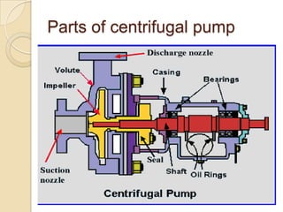
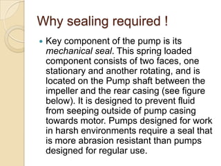
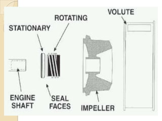
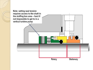
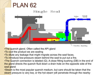
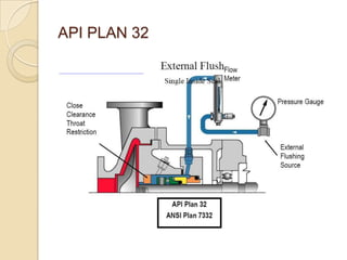
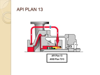
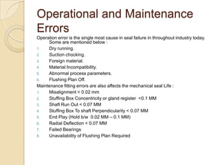
Mechanical SealBy Mr. Om Pratap Singh
Parts of centrifugal pump
Why sealing required !Key component of the pump is its mechanical seal. This spring loaded component consists of two faces, one stationary and another rotating, and is located on the Pump shaft between the impeller and the rear casing (see figure below). It is designed to prevent fluid from seeping outside of pump casing towards motor. Pumps designed for work in harsh environments require a seal that is more abrasion resistant than pumps designed for regular use.
Mechanical Seal Vs Gland PackingsLoss of Material   A basic comparison with the leakage rate for the compression packings and mechanical seal yields the followings:   (25 drop/minx60x24)+45 drops/day=800   a leakage ratio of packings to seals of 800:1Power saving: 50% Less power consumption in Mechanical seal.
Cross-sectional view of mechanical seal
Gland packing
How Mechanical Seal Works !
Secondary Sealing Elements
Need of API Flushing PlanTo lubricate and cool the pumps mechanical seal.To remove foreign particles to minimize abrasion.To remove carbon deposition on compression unit.To dilute ingresses material between Seal faces.It could provide safety to the seal from dry running to the some extent.To maintain the operational parameters of mechanical seal for which it is designed.
PLANT 11Plan 11. A line is connected from the discharge side of the pump and recirculated through an orifice into the gland flush connection. Orifices are hard to size and since many pumping fluids contain solids orifices are easy to clog
PLAN 62The quench gland. Often called the API gland
To cool the product we are sealing
To dilute any leakage that might migrate across the seal faces.
To introduce low-pressure steam behind the seal to put out a fire.
The Quench connection is labeled (Q). A close fitting bushing (DB) in the end of the gland directs the quench fluid down a drain hole on the opposite side of the seal gland
Steam is the most popular quench medium, but care should be taken that the steam pressure is very low, or the hot steam will penetrate through the nearby bearing seals and contaminate the bearing oil. API PLAN 32
API PLAN 13
Operational and Maintenance ErrorsOperation error is the single most cause in seal failure in throughout industry today. Some are mentioned below :Dry running.Suction chocking.Foreign material.Material Incompatibility.Abnormal process parameters.Flushing Plan Off.Maintenance fitting errors are also affects the mechanical seal Life :Misalignment < 0.02 mmStuffing Box Concentricity or gland register  <0.1 MMShaft Run Out < 0.07 MMStuffing Box To shaft Perpendicularity < 0.07 MMEnd Play (Hold b/w  0.02 MM – 0.1 MM)Radial Deflection < 0.07 MM Failed BearingsUnavailability of Flushing Plan Required
Stuffing Box Concentricity or gland register  <0.1 MM
Stuffing Box To shaft Perpendicularity < 0.07 MM

Mechanical Seal Vs Gland Packing

  • 1.
    Mechanical SealBy Mr.Om Pratap Singh
  • 2.
  • 3.
    Why sealing required!Key component of the pump is its mechanical seal. This spring loaded component consists of two faces, one stationary and another rotating, and is located on the Pump shaft between the impeller and the rear casing (see figure below). It is designed to prevent fluid from seeping outside of pump casing towards motor. Pumps designed for work in harsh environments require a seal that is more abrasion resistant than pumps designed for regular use.
  • 5.
    Mechanical Seal VsGland PackingsLoss of Material A basic comparison with the leakage rate for the compression packings and mechanical seal yields the followings: (25 drop/minx60x24)+45 drops/day=800 a leakage ratio of packings to seals of 800:1Power saving: 50% Less power consumption in Mechanical seal.
  • 6.
  • 8.
  • 9.
  • 11.
  • 12.
    Need of APIFlushing PlanTo lubricate and cool the pumps mechanical seal.To remove foreign particles to minimize abrasion.To remove carbon deposition on compression unit.To dilute ingresses material between Seal faces.It could provide safety to the seal from dry running to the some extent.To maintain the operational parameters of mechanical seal for which it is designed.
  • 13.
    PLANT 11Plan 11.A line is connected from the discharge side of the pump and recirculated through an orifice into the gland flush connection. Orifices are hard to size and since many pumping fluids contain solids orifices are easy to clog
  • 14.
    PLAN 62The quenchgland. Often called the API gland
  • 15.
    To cool theproduct we are sealing
  • 16.
    To dilute anyleakage that might migrate across the seal faces.
  • 17.
    To introduce low-pressuresteam behind the seal to put out a fire.
  • 18.
    The Quench connectionis labeled (Q). A close fitting bushing (DB) in the end of the gland directs the quench fluid down a drain hole on the opposite side of the seal gland
  • 19.
    Steam is themost popular quench medium, but care should be taken that the steam pressure is very low, or the hot steam will penetrate through the nearby bearing seals and contaminate the bearing oil. API PLAN 32
  • 20.
  • 21.
    Operational and MaintenanceErrorsOperation error is the single most cause in seal failure in throughout industry today. Some are mentioned below :Dry running.Suction chocking.Foreign material.Material Incompatibility.Abnormal process parameters.Flushing Plan Off.Maintenance fitting errors are also affects the mechanical seal Life :Misalignment < 0.02 mmStuffing Box Concentricity or gland register <0.1 MMShaft Run Out < 0.07 MMStuffing Box To shaft Perpendicularity < 0.07 MMEnd Play (Hold b/w 0.02 MM – 0.1 MM)Radial Deflection < 0.07 MM Failed BearingsUnavailability of Flushing Plan Required
  • 22.
    Stuffing Box Concentricityor gland register <0.1 MM
  • 23.
    Stuffing Box Toshaft Perpendicularity < 0.07 MM