SlideShare a Scribd company logo
Bosch Rexroth AG, RE 17042, edition: 2013-07
Project planning software Interactive Catalog System
www.boschrexroth.com/icsOnline
Mounting elements
for hydraulic cylinders
RE 17042 
Edition: 2013-07
Replaces: 13.06Mounting elements
Features
Mounting elements:
▶ Plain clevis
▶ Swivel head
▶ Fork clevis
▶ Bearing bracket
▶ Clevis bracket and eye bracket
▶ Trunnion bracket
▶ Bolts
Contents
Features 1
Mounting element overview 2, 3
Dimensions:
Swivel head CGK 4, 5
Clevis bracket CLCC 6, 7
Fork clevis CCKA 8
Eye bracket CLEA 9
Clevis bracket CLCB 10, 11
Trunnion bracket CLTA 12, 13
Swivel head CGKA 14
Swivel head CGKL 15
Swivel head CGKD 16, 17
Trunnion bracket CLTB 18, 19
Clevis bracket CLCA 20, 21
Clevis bracket CLCD 22, 23
Plain clevis CSA 24, 25
Swivel head CGA 26, 27
Swivel head CGAK 28, 29
Swivel head CGAS 30, 31
Fork clevis CCKB 32, 33
Swivel head CGKD 34, 35
Trunnion bracket CLTB 36, 37
Clevis bracket CLCA 38, 39
Clevis bracket CLCD 40, 41
H3121_d
2/44 Mounting elements
Bosch Rexroth AG, RE 17042, edition: 2013-07
Mounting element overview
Assembly (symbolic representation) Denomination /
type
To be attached
to series
Page
Swivel head
CGK
ISO 12240-4
CD70/CG70
CD210/CG210
4, 5
Clevis bracket
CLCC
6, 7
Fork clevis
CCKA
8
Eye bracket
CLEA
9
Clevis bracket
(clampable)
CLCB
ISO 8133
DIN 24556
CDT3/CGT3/CST3
10, 11
Trunnion bracket
CLTA
12, 13
Swivel head
(clampable)
CGKA
ISO 8133
DIN 24555
14
Swivel head
CGKL
ISO 12240-4
CDL2
15
Swivel head
(clampable)
CGKD
ISO 8132
16, 17
Trunnion bracket
CLTB
ISO 8132
18, 19
Clevis bracket
(clampable)
CLCA
ISO 8132
form B
20, 21
Clevis bracket
(clampable)
CLCD
ISO 8132
form A
22, 23
Mounting elements 3/44
RE 17042, edition: 2013-07, Bosch Rexroth AG
Assembly (symbolic representation) Denomination /
type
To be attached
to series
Page
Plain clevis
CSA
CDH1/CGH1/CSH1
CDH3/CGH3/CSH3
24, 25
Swivel head
CGA
26, 27
Swivel head
(clampable)
CGAK
28, 29
Swivel head
(clampable)
CGAS
30, 31
Fork clevis
(clampable)
CCKB
ISO 8132
CDH2/CGH2/CSH2
CDM1/CGM1/CSM1
32, 33
Swivel head
(clampable)
CGKD
ISO 8132
34, 35
Trunnion bracket
CLTB
ISO 8132
36, 37
Clevis bracket
(clampable)
CLCA
ISO 8132
form B
38, 39
Clevis bracket
(clampable)
CLCD
ISO 8132
form A
40, 41
Mounting element overview
Z
B1
2)
ØD2
B2
50°
D1
SW1
T1
L3
L2
L4
L1
D3
ØD4
ØD5
1)
Z
4/44 Mounting elements
Bosch Rexroth AG, RE 17042, edition: 2013-07
Series
Type Material no. B1
-0,12
B2 D1 ØD2
h5
D3
max.
ØD4
max.
ØD5
max.
CD70 / CG70 CD210 / CG210
ØAL ØAL ØMM
25 — — CGK 10 3) R900001653 9 7 M10 10 30 16 20
32 — — CGK 12 3) R900001327 10 8 M12 12 35 19 23
40 40
16
CGK 15 4) R900001328 12 10 M14 15 41 22 27
18
50
40 25
CGK 20 4) R900001329 16 13 M20x1,5 20 54 28 36
50
22
25
63
50 36
CGK 25 R900001330 20 17 M24x2 25 65 35 44
63
25
28
80
63
36
CGK 30 R900001331 22 19 M30x2 30 75 42 5245
80 36
— 80 45 CGK 35 R900012486 25 21 M36x3 35 84 47 60
100 80 56 CGK 40 R900001332 28 23 M39x3 40 94 52 67
125 100 45 CGK 45 R900001333 32 27 M42x3 45 104 58 72
150
100
50
CGK 50 R900001334 35 30 M45x3 50 114 62 77
70
125
50
56
200
125
63
CGK 60 R900001335 44 38 M52x3 60 137 70 90
63
150
90
70
—
150
80
CGK 80 R900001928 55 47 M64x4 80 182 95 112100
180 80
Dimensions: Swivel head CGK for series CD70/CG70 and CD210/CG210
(dimensions in mm)
ISO 12240-4
Mounting elements 5/44
RE 17042, edition: 2013-07, Bosch Rexroth AG
Dimensions: Swivel head CGK for series CD70/CG70 and CD210/CG210
(dimensions in mm)
Series
Type L1 L2 L3
max.
L4
min.
T1
min.
SW1 5) Z 5) m
kg
C0
6)
kN
Fadm
7)
kN
CD70 / CG70 CD210 / CG210
ØAL ØAL ØMM
25 — — CGK 10 3) 6,5 43 60 13 15 15 / 16 12° – 15° 0,07 17,6 5,8
32 — — CGK 12 3) 7 50 69 17 18 19 10° – 11° 0,1 24,5 8,1
40 40
16
CGK 15 4) 8 61 83 19 21 22 8° – 12° 0,16 36 11,9
18
50
40 25
CGK 20 4) 10 77 106 24 30 30 / 32 9° 0,34 60 19,8
50
22
25
63
50 36
CGK 25 12 94 128 30 36 36 7° 0,6 83 27,4
63
25
28
80
63
36
CGK 30 15 110 149 34 45 41 / 46 6° 0,9 110 36,345
80 36
— 80 45 CGK 35 15 125 169 40 60 50 6° 1,4 146 48,2
100 80 56 CGK 40 18 142 191 46 65 55 7° 2,0 180 59,4
125 100 45 CGK 45 20 145 199 50 65 60 / 65 7° 2,7 240 79,2
150
100
50
CGK 50 20 160 219 58 68 65 / 70 6° 3,5 290 95,7
70
125
50
56
200
125
63
CGK 60 20 175 246 73 70 75 6° 5,6 450 148,5
63
150
90
70
—
150
80
CGK 80 25 230 324 98 85 100 6° 13,1 750 247,5100
180 80
ØAL = piston Ø
ØMM = piston rod Ø
1) Lubricating nipple, cone head form A according to DIN 71412
2) Bolt Ø m6 required
3) Cannot be re-lubricated
4) Can be re-lubricated via lubricating hole in housing
5) Dimensions may differ depending on the manufacturer
6) C0 = static load rating of the swivel head
7) Fadm = maximum admissible load on the swivel head during
oscillatory or alternating loads
Notice!
Geometry and dimensions may differ depending on the
manufacturer. In case of combination with other mount-
ing elements, check the suitability.
LE
CM
1)
CL1
CL2
FL
R
UD
R
UD
ØHB
b
ER
ØCK
6/44 Mounting elements
Bosch Rexroth AG, RE 17042, edition: 2013-07
Dimensions: Clevis bracket CLCC for series CD70/CG70 and CD210/CG210
(dimensions in mm)
Series
Type Material no. ØCK
H9 1)
CL1
h16
CL2
max.
CM
A12
FL
js12
CD70 / CG70 CD210 / CG210
ØAL 2) ØAL 3) ØAL ØMM ØAL 3)
25 — — — — CLCC 10 R900318440 10 25 37 9 35
32
25 — —
— CLCC 12 R900318423 12 25 37 10 35
32 — —
40 40 40
16
40 CLCC 15 R900318468 15 35 48 12 45
18
50
50 40 25
50 CLCC 20 R900318469 20 50 64 16 58
50
22
63
25
63
80 50 36
63 CLCC 25 R900318470 25 60 74 20 75
63
25
100
28
80 125
63
36
— CLCC 30 R900318471 30 60 74 22 7545
80 36
— 150 80 45 80 CLCC 35 R900318472 35 70 93 25 90
100 — 80 56 100 CLCC 40 R900318473 40 70 93 28 90
125 200 100 45 125 CLCC 45 R900318481 45 110 133 32 125
150 —
100
50
150 CLCC 50 R900318482 50 110 133 35 125
70
125
50
56
200 —
125
63
180 CLCC 60 R900318483 60 125 148 44 155
90
150
63
70
— —
150
80
— CLCC 80 R900318477 80 140 163 55 130100
180 80
— —
180 90
— CLCC 81 R900318478 80 140 163 60 150
200
90
100
— — 180 125 — CLCC 90 R900318479 90 140 163 65 150
— — 200 140 — CLCC 100 R900318480 100 150 175 70 165
— — — 200 CLCC 70 R900318484 70 125 148 49 155
Suitable for swivel head
type CGK… or CGA…
Mounting elements 7/44
RE 17042, edition: 2013-07, Bosch Rexroth AG
Dimensions: Clevis bracket CLCC for series CD70/CG70 and CD210/CG210
(dimensions in mm)
ØAL = piston Ø
ØMM = piston rod Ø
1) Bolt Ø m6 required
(bolt and bolt lock are included in the scope of delivery)
2) When mounted on the piston rod with CGK… or CGA
3) When mounted on the cylinder base (mounting type "B")
Series
Type ØHB
H13
ER
max.
LE
min.
UD
max.
R
js14
b
max.
m
kg
CD70 / CG70 CD210 / CG210
ØAL 2) ØAL 3) ØAL ØMM ØAL 3)
25 — — — — CLCC 10 5,5 13 25 45 33 24 0,3
32
25 — —
— CLCC 12 5,5 13 25 45 33 24 0,3
32 — —
40 40 40
16
40 CLCC 15 11 17 35 75 50 32 0,8
18
50
50 40 25
50 CLCC 20 13,5 22 42 90 65 40 1,8
50
22
63 25
63
80 50 36
63 CLCC 25 13,5 25 59 95 70 45 2,5
63
25
100 28
80 125
63
36
— CLCC 30 13,5 25 59 95 70 45 2,545
80 36
— 150 80 45 80 CLCC 35 17,5 35 68 130 95 65 6,0
100 — 80 56 100 CLCC 40 17,5 35 68 130 95 65 6,0
125 200 100 45 125 CLCC 45 26 46 100 180 135 85 15,0
150 —
100
50
150 CLCC 50 26 46 100 180 135 85 15,0
70
125
50
56
200 —
125
63
180 CLCC 60 33 66 125 225 170 125 28,0
90
150
63
70
— —
150
80
— CLCC 80 33 75 100 245 190 140 33,0100
180 80
— —
180 90
— CLCC 81 33 75 120 245 190 140 34,0
200
90
100
— — 180 125 — CLCC 90 33 75 120 245 190 140 35,0
— — 200 140 — CLCC 100 33 95 135 255 200 170 41,0
— — — 200 CLCC 70 33 80 125 225 170 145 28,0
Notice!
Geometry and dimensions may differ depending on the
manufacturer. In case of combination with other mount-
ing elements, check the suitability.
ØCK
CM 1)
CL1
CL2
KK
LE
CE
MR
b
8/44 Mounting elements
Bosch Rexroth AG, RE 17042, edition: 2013-07
Dimensions: Fork clevis CCKA for series CD70/CG70 and CD210/CG210
(dimensions in mm)
ØMM = piston rod Ø
1) Bolt Ø f7 required
(bolt and bolt lock are included in the scope of delivery)
2) Only possible with thread design "C".
Series
Type 2) Material no. ØCK
H7 1)
CL1
h16
CL2
max.
CM
A12
CE
js12
KK LE
min.
MR
max.
b
max.
m
kg
CD70 / CG70 CD210 / CG210
ØMM ØMM
16 16
CCKA 10 R900318486 12,7 44 56 20 38 M10x1,5 19 13 26 0,2
18 18
22 22 CCKA 16 R900318488 19,1 65 77 32,5 54 M16x1,5 26 19 38 1,0
25 25
CCKA 20 R900318487 19,1 65 77 32,5 54 M20x1,5 26 19 38 1,0
28 28
36 36 CCKA 26 R900318489 25,43 77 92 39 75 M26x1,5 34 26 52 2,4
45 45 CCKA 33 R900318491 34,95 100 118 51,5 95 M33x2 45 35 70 4,5
50 50
CCKA 39 R900318494 44,48 127 147 65 114 M39x2 57 45 90 8,5
56 56
63 63
CCKA 48 R900318496 50,83 127 147 65 140 M48x2 64 50 100 13,0
70 70
80 80 CCKA 58 R900541067 63,5 154 176 78 165 M58x2 76 65 130 23,0
90 90 CCKA 64 R900318498 76,23 154 176 78 172 M64x2 83 70 140 25,0
Notice!
Geometry and dimensions may differ depending on the
manufacturer. In case of combination with other mount-
ing elements, check the suitability.
ØCK
R
UD
ØHB
b
ER
LE
EM
1)
FL
R
UD
2)
Mounting elements 9/44
RE 17042, edition: 2013-07, Bosch Rexroth AG
Dimensions: Eye bracket CLEA for series CD70/CG70 and CD210/CG210
(dimensions in mm)
ØAL = piston Ø
ØMM = piston rod Ø
1) Lubricating nipple, cone head form A according to DIN 71412
2) Suitable for fork clevis type CCKA...
3) When mounted on the cylinder base (mounting type "G")
4) When mounted on the piston rod with CCKA...
Series
Type Material no. ØCK
H7 2)
EM
h13
FL
js12
ØHB
H13
ER
max.
LE
min.
UD
max.
R
js14
b m
kg
CD70 / CG70 CD210 / CG210
ØAL 3) ØMM 4) ØAL 3) ØMM 4)
32
16
40
16
CLEA 10 R900318516 12,7 20 28,5 11 13 18,5 63 41,5 24 0,4
40
50
18 18
63
80 22 50 22
CLEA 20 R900318518 19,1 32,5 47,5 13,5 22 31,5 89 65 40 1,6100 25 25
63
125 28 28
150
36 80 36 CLEA 26 R900318519 25,43 39 57 17,5 30 38 114 82,5 55 2,3
200
— 45 100 45 CLEA 33 R900318520 34,95 51,5 76 17,5 41 54 127 97 75 5,8
—
50
125
50
CLEA 39 R900318521 44,48 65 79,5 22 49 57 165 126 90 10,0
56 56
—
63
150
63
CLEA 48 R900318522 50,83 65 89 26 56 64 190 145,5 105 14,0
70 70
— 80 180 80 CLEA 58 R900318524 63,53 78 101,5 30 69 77 216 167 130 21,0
— 90 200 90 CLEA 64 R900318523 76,23 78 108 33 77 83 242 190,5 145 26,0
Notice!
Geometry and dimensions may differ depending on the
manufacturer. In case of combination with other mount-
ing elements, check the suitability.
CG
ØCF
ØHB
CO
LG
GL
1)LO
SR
FM
KC
FO
TA
RE
ØS
1
UJ
SL
CP KL
LJ
UK
10/44 Mounting elements
Bosch Rexroth AG, RE 17042, edition: 2013-07
Dimensions: Clevis bracket CLCB - AB 5 (clampable) for series CDT3/CGT3/CST3
(dimensions in mm)
ISO 8133
DIN 24556
Type Material no.
Nominal
force
kN
ØCF
K7 1)
CP
h14
CG
+0,1
+0,3
CO
N9
FO
js14
FM
js11
GL
js13
ØHB ØS
CLCB 12 R900326960 8 12 30 10 10 16 40 46 9 15
CLCB 16 R900327372 12,5 16 40 14 16 18 50 61 11 18
CLCB 20 R900327373 20 20 50 16 16 20 55 64 14 3) 20
CLCB 25 R900326961 32 25 60 20 25 22 65 78 16 3) 24
CLCB 30 R900327374 50 30 70 22 25 24 85 97 18 3) 26
CLCB 40 R900327375 80 40 80 28 36 24 100 123 22 33
CLCB 50 R900327376 125 50 100 35 36 35 125 155 30 48
CLCB 60 R900327377 200 60 120 44 50 35 150 187 39 60
CLCB 80 R900327378 320 80 160 55 50 35 190 255 45 80
CLCB 100 R900327379 500 100 200 70 63 35 210 285 48 80
Mounting elements 11/44
RE 17042, edition: 2013-07, Bosch Rexroth AG
Dimensions: Clevis bracket CLCB - AB 5 (clampable) for series CDT3/CGT3/CST3
(dimensions in mm)
Type
KC
+0,3
0
KL LG LJ LO RE
js13
SL SR
max.
TA
js13
UJ UK m 2)
kg
CLCB 12 3,3 8 28 29 56 55 40 12 40 75 60 0,6
CLCB 16 4,3 8 37 38 74 70 50 16 55 95 80 1,3
CLCB 20 4,3 10 39 40 80 85 62 20 58 120 90 2,1
CLCB 25 5,4 10 48 49 98 100 72 25 70 140 110 3,2
CLCB 30 5,4 13 62 63 120 115 85 30 90 160 135 6,5
CLCB 40 8,4 16 72 73 148 135 100 40 120 190 170 12,0
CLCB 50 8,4 19 90 92 190 170 122 50 145 240 215 23,0
CLCB 60 11,4 20 108 110 225 200 145 60 185 270 260 37,0
CLCB 80 11,4 26 140 142 295 240 190 80 260 320 340 79,0
CLCB 100 12,4 30 150 152 335 300 235 100 300 400 400 140,0
1) Bolt Ø h6 required, suitable for swivel head CGKA...
(bolt and bolt lock are included in the scope of delivery)
2) m = weight of clevis bracket in kg
3) Dimensions may differ from the standard depending on the
manufacturer
Notice!
Geometry and dimensions may differ depending on the
manufacturer. In case of combination with other mount-
ing elements, check the suitability.
2)
FS
NH
"A"
"A"
l1
ØCR
KC
CO
TH
UL
FN
FK
l2
1)
1)
ØHB
l3x45
12/44 Mounting elements
Bosch Rexroth AG, RE 17042, edition: 2013-07
Dimensions: Trunnion bracket CLTA - AT 4 for series CDT3/CGT3/CST3
(dimensions in mm)
CLTA 12-20
or
ØAL = piston Ø
1) Lubricating nipple, cone form A according to DIN 71412
2) Inside
3) Dimensions may differ depending on the manufacturer
4) Nominal force applies to applications in pairs
5) m = weight per pair in kg, brackets are delivered in pairs
Notice!
Geometry and dimensions may differ depending on the
manufacturer. In case of combination with other mount-
ing elements, check the suitability.
Series
CDT3 / CGT3 / CST3
ØAL
Type Material no.
Nominal
force
kN 4)
ØCR
H7
CO
N9
FK
js12
FN
max.
FS
js14
ØHB
H13
KC
+0,3
0
NH
max.
TH
js14
UL
max.
l1 l2 l3 m 5 )
kg
25 CLTA 12 R901071355 8 12 10 38 55 8 9 3,3 17 3) 40 63 25 25 1 0,5
32 CLTA 16 R901071364 12,5 16 16 45 65 10 11 4,3 21 50 80 30 30 1 0,9
40 CLTA 20 R901071365 20 20 16 55 80 10 11 4,3 21 60 90 40 38 1,5 1,35
FS
NH
"A"
"A"
l1
ØCR
KC
CO
TH
UL
FN
FK
l2
1)
ØHB
1)
2)
l3x45°
Mounting elements 13/44
RE 17042, edition: 2013-07, Bosch Rexroth AG
CLTA 25-100
ØAL = piston Ø
1) Lubricating nipple, cone form A according to DIN 71412
2) Inside
3) Dimensions may differ depending on the manufacturer
4) Nominal force applies to applications in pairs
5) m = weight per pair in kg, brackets are delivered in pairs
Notice!
Geometry and dimensions may differ depending on the
manufacturer. In case of combination with other mount-
ing elements, check the suitability.
or
Dimensions: Trunnion bracket CLTA - AT 4 for series CDT3/CGT3/CST3
(dimensions in mm)
Series
CDT3 / CGT3 / CST3
ØAL
Type Material no.
Nominal
force
kN 4)
ØCR
H7
CO
N9
FK
js12
FN
max.
FS
js14
ØHB
H13
KC
+0,3
0
NH
max.
TH
js14
UL
max.
l1 l2 l3 m 5)
kg
50 CLTA 25 R901071368 32 25 25 65 90 12 14 3) 5,4 26 80 110 56 45 1,5 2,4
63 CLTA 32 R901071377 50 32 25 75 110 15 18 3) 5,4 33 110 150 70 52 2 5,0
80 CLTA 40 R901071380 80 40 36 95 140 16 22 8,4 41 125 170 88 60 2,5 8,5
100 CLTA 50 R901071385 125 50 36 105 150 20 26 8,4 51 160 210 90 72 2,5 15
125 CLTA 63 R901071395 200 63 50 125 195 25 33 11,4 61 200 265 136 87 3 30
160 CLTA 80 R901071398 320 80 50 150 230 31 39 11,4 81 250 325 160 112 3,5 59
200 CLTA 100 R901071400 500 100 63 200 300 42 52 12,4 101 320 410 200 150 4,5 131
EU
EN
KK
C
ØCN
Øb
AX
3°
3°
2)
1)
CH
LF
MA
14/44 Mounting elements
Bosch Rexroth AG, RE 17042, edition: 2013-07
Dimensions: Swivel head CGKA - AP 6 (clampable) for series CDT3/CGT3/CST3
(dimensions in mm)
ISO 8133
DIN 24555
Type Material no. KK AX
min.
Øb C
max.
CH
js13
ØCN 2) EN EU
max.
LF
min.
MA
7)
Nm
m 8)
kg
C0
9)
(head)
kN
Fadm
10)
kN
CGKA 12 3) R900327186 M10x1,25 15 17 40 42 12 –0,008 10 –0,12 8 16 9,5 0,15 17 6,3
CGKA 16 4) R900327192 M12x1,25 17 21 45 48 16 –0,008 14 –0,12 11 20 9,5 0,25 28,5 10,5
CGKA 20 4) R900306874 M14x1,5 19 25 55 58 20 –0,012 16 –0,12 13 25 23 0,43 42,5 15,7
CGKA 25 R900327191 M16x1,5 23 30 65 68 25 –0,012 20 –0,12 17 30 23 0,73 67 24,7
CGKA 30 R900327187 M20x1,5 29 36 80 85 30 –0,012 22 –0,12 19 35 46 1,3 108 39,9
CGKA 40 R900327188 M27x2 37 45 100 105 40 –0,012 28 –0,12 23 45 46 2,3 156 57,6
CGKA 50 R900327368 M33x2 46 55 125 130 50 –0,012 35 –0,12 30 58 80 4,4 245 90,4
CGKA 60 R900327369 M42x2 57 68 160 150 60 –0,012 44 –0,12 38 68 195 8,4 380 140,2
CGKA 80 R900327370 M48x2 64 90 205 185 80 –0,015 55 –0,15 47 82 6) 385 15,6 585 215,9
CGKA 100 R900327371 M64x3 86 110 240 240 100 –0,02 70 –0,2 57 116 660 28 865 319,2
CGKD 100 5) R900322030 M80x3 96 110 210 210 100 H7 100 h12 84 98 385 28 1060 391,1
CGKD 125 5) R900322026 M100x3 113 135 262 260 125 H7 125 h12 102 120 385 43 1200 442,8
1) Lubricating nipple, cone head form A according to DIN 71412
2) Bolt Ø h6 required
3) Cannot be re-lubricated
4) Can be re-lubricated via lubricating hole
5) Swivel head according to ISO 8132, bolt Ø m6 required
6) Dimensions may differ from the standard depending on
the manufacturer
7) MA = tightening torque
The swivel head must always be screwed against the shoulder of
the piston rod. Afterwards, the clamping screws must be
tightened with the specified tightening torque.
8) m = weight of swivel head in kg
9) C0 = static load rating of the swivel head
10) Fadm = maximum admissible load on the swivel head during
oscillatory or alternating loads
Notice!
Geometry and dimensions may differ depending on the
manufacturer. In case of combination with other mount-
ing elements, check the suitability.
NV
CP
KK
BA
KW
LF
EU
EN
C
10
CN
10
Mounting elements 15/44
RE 17042, edition: 2013-07, Bosch Rexroth AG
Dimensions: Swivel head CGKL for series CDL2
(dimensions in mm)
Series
CDL2
Type Material no. KK BA
min.
C ØCN
-0,008
CP
max.
EN
h12
EU
max.
KW LF
min.
NV m 1)
kg
C0
2)
kN
Fadm
3)
kN
ØAL ØMM
25 14 CGKL 10 3712500031 M10 26 29 10 48 9 7,5 5 15 16 0,1 22 8,1
32 18 CGKL 12 3713200031 M12 28 34 12 54 10 8,5 6 18 18 0,1 30,4 11,2
ISO 12240-4
ØAL = piston Ø
ØMM = piston rod Ø
1) m = weight of swivel head in kg
2) C0 = static load rating of the swivel head in kN
3) Fadm = maximum admissible load on the swivel head during
oscillatory or alternating loads
Notice!
Geometry and dimensions may differ depending on the
manufacturer. In case of combination with other mount-
ing elements, check the suitability.
EN
EU
CH
LF
1)
KK
AV
N
2)
EF
MA
3)
4
4
CN
16/44 Mounting elements
Bosch Rexroth AG, RE 17042, edition: 2013-07
Dimensions: Swivel head CGKD (clampable) for series CDL2
(dimensions in mm)
ISO 8132
Series
CDL2
Type Material no.
Nominal
force
kN
AV
min.
N
max.
CH
js13
EF
max.
ØCN
H7 2)
EN
h12
EU
max.
ØAL ØMM
40 22 CGKD 20 R900308576 20 23 28 52 25 20 20 17,5
40 25
CGKD 25 R900323332 32 29 31 65 32 25 25 22
50 28
50 32
CGKD 32 R900322049 50 37 38 80 40 32 32 28
63 36
63 40
CGKD 40 R900322029 80 46 47 97 50 40 40 34
80 45
80 50
CGKD 50 R900322719 125 57 58 120 63 50 50 42
100 56
100 63
CGKD 63 R900322028 200 64 70 140 72,5 63 63 53,5
125 70
125 80 CGKD 80 R900322700 320 86 91 180 92 80 80 68
160 100 CGKD 100 R900322030 500 96 110 210 114 100 100 85,5
200 125 CGKD 125 R900322026 800 113 135 260 160 125 125 105
Mounting elements 17/44
RE 17042, edition: 2013-07, Bosch Rexroth AG
ØAL = piston Ø
ØMM = piston rod Ø
1) Lubricating nipple, cone head form A according to DIN 71412
2) Bolt Ø m6 required
3) MA = tightening torque in Nm
The swivel head must always be screwed against the shoulder of
the piston rod. Afterwards, the clamping screws must be
tightened with the specified tightening torque
4) m = weight of swivel head in kg
5) C0 = static load rating of the swivel head in kN
6) Fadm = maximum admissible load on the swivel head in kN during
oscillatory or alternating loads
Dimensions: Swivel head CGKD (clampable) for series CDL2
(dimensions in mm)
Notice!
Geometry and dimensions may differ depending on the
manufacturer. In case of combination with other mount-
ing elements, check the suitability.
Series
CDL2
Type KK LF
min.
Clamping screws
ISO 4762-10.9
MA
3)
Nm
m 4)
kg
C0
5)
kN
Fadm
6)
kN
ØAL ØMM
40 22 CGKD 20 M16x1,5 20,5 M8x20 25 0,35 48 17,7
40 25
CGKD 25 M20x1,5 25,5 M8x20 30 0,65 78 28,8
50 28
50 32
CGKD 32 M27x2 30 M10x25 59 1,15 114 42,1
63 36
63 40
CGKD 40 M33x2 39 M10x30 59 2,1 204 75,3
80 45
80 50
CGKD 50 M42x2 47 M12x35 100 4 310 114,4
100 56
100 63
CGKD 63 M48x2 58 M16x40 250 7,2 430 158,7
125 70
125 80 CGKD 80 M64x3 74 M20x50 490 15 695 265,5
160 100 CGKD 100 M80x3 94 M24x60 840 25,5 1060 391,1
200 125 CGKD 125 M100x3 116 M24x70 840 52,5 1430 527,7
"A"
l1
ØCR
KC
CO
TH
UL
FN
FK
l2
1)
ØHB
2)
FS
NH
"A"
l3x45
"A"
l1
ØCR
KC
CO
TH
UL
FN
FK
l2
1)
ØHB
18/44 Mounting elements
Bosch Rexroth AG, RE 17042, edition: 2013-07
CLTB 12 ... 20
Dimensions: Trunnion bracket CLTB for series CDL2
(dimensions in mm)
CLTB 25 ... 80
Series
CDL2
Type 3) Material no. Nominal force
kN 4)
ØCR
H7
CO
N9
FK
js12
FN
max.
FS
js14
ØHB
H13
ØAL ØMM
25 14 CLTB 12 R900772607 8 12 10 34 50 8 9
32 18 CLTB 16 R900772608 12,5 16 16 40 60 10 11
40 22 CLTB 20 R900772609 20 20 16 45 70 10 11
40 25
CLTB 25 R900772610 32 25 25 55 80 12 13,5
50 28
50 32
CLTB 32 R900772611 50 32 25 65 100 15 17,5
63 36
63 40
CLTB 40 R900772612 80 40 36 76 120 16 22
80 45
80 50
CLTB 50 R900772613 125 50 36 95 140 20 26
100 56
100 63
CLTB 63 R900772614 200 63 50 112 180 25 33
125 70
125 80 CLTB 80 R900772615 320 80 50 140 220 31 39
ISO 8132
Mounting elements 19/44
RE 17042, edition: 2013-07, Bosch Rexroth AG
Notice!
Geometry and dimensions may differ depending on the
manufacturer. In case of combination with other mount-
ing elements, check the suitability.
The trunnion brackets are suitable for mounting
type MT4.
Dimensions: Trunnion bracket CLTB for series CDL2
(dimensions in mm)
ØAL = piston Ø
ØMM = piston rod Ø
1) Lubricating nipple, cone head form A according to DIN 71412
2) Contact surface trunnion (inside)
3) Bearing blocks are always supplied in pairs
4) Nominal force applies to applications in pairs
5) m = weight of trunnion bracket in kg (specified per pair)
Series
CDL2
Type 3) KC
+0,3
l1 l2 l3 NH
max.
TH
js14
UL
max.
m 5)
kg
ØAL ØMM
25 14 CLTB 12 3,3 25 25 1 17 40 63 0,4
32 18 CLTB 16 4,3 30 30 1 21 50 80 0,85
40 22 CLTB 20 4,3 40 38 1,5 21 60 90 1,2
40 25
CLTB 25 5,4 56 45 1,5 26 80 110 2,1
50 28
50 32
CLTB 32 5,4 70 52 2 33 110 150 4,55
63 36
63 40
CLTB 40 8,4 88 60 2,5 41 125 170 7,3
80 45
80 50
CLTB 50 8,4 100 75 2,5 51 160 210 14,5
100 56
100 63
CLTB 63 11,4 130 85 3 61 200 265 23,1
125 70
125 80 CLTB 80 11,4 160 112 3,5 81 250 325 52,3
1)
ØS
ØHB
COFOFG
KC
RG
UX
MR
1
ØCK
SL
CL KL
CM
RF
UK
LE
FL
20/44 Mounting elements
Bosch Rexroth AG, RE 17042, edition: 2013-07
Dimensions: Clevis bracket CLCA (clampable) for series CDL2
(dimensions in mm)
ISO 8132, form B
Series
CDL2
Type Material no.
Nominal
force
kN
ØCK
H9 1)
CL
h16
CM
A12
CO
N9
FG
js14
FL
js12
FO
js14
ØHB
H13
ØAL ØMM
25 14 CLCA 10 2) 3) 5 10 24 10 8 2 32 10 6,6
32 18 CLCA 12 2) R900542861 8 12 28 12 10 2 34 10 9
40 22 CLCA 20 R900542863 20 20 45 20 16 7,5 45 10 11
40 25
CLCA 25 R900542864 32 25 56 25 25 10 55 10 13,5
50 28
50 32
CLCA 32 R900542865 50 32 70 32 25 14,5 65 6 17,5
63 36
63 40
CLCA 40 R900542866 80 40 90 40 36 17,5 76 6 22
80 45
80 50
CLCA 50 R900542867 125 50 110 50 36 25 95 0 26
100 56
100 63
CLCA 63 R900542868 200 63 140 63 50 33 112 0 33
125 70
125 80 CLCA 80 R900542869 320 80 170 80 50 45 140 0 39
160 100 CLCA 100 3) 500 100 210 100 63 52,5 180 0 52
200 125 CLCA 125 3) 800 125 270 125 80 75 230 0 52
Mounting elements 21/44
RE 17042, edition: 2013-07, Bosch Rexroth AG
Series
CDL2
Type KC
+0,3
KL LE
min.
MR
max.
RF
js14
RG
js14
ØS SL UK
max.
UX
max.
m 4)
kg
ØAL ØMM
25 14 CLCA 10 2) 3,3 8 22 10 39 44 11 34 56 60 0,33
32 18 CLCA 12 2) 3,3 8 22 12 52 45 15 38 72 65 0,45
40 22 CLCA 20 4,3 10 30 20 75 70 18 58 100 95 1,5
40 25
CLCA 25 5,4 10 37 25 90 85 20 69 120 115 3
50 28
50 32
CLCA 32 5,4 13 43 32 110 110 26 87 145 145 4,5
63 36
63 40
CLCA 40 8,4 16 52 40 140 125 33 110 185 170 8,5
80 45
80 50
CLCA 50 8,4 19 65 50 165 150 40 133 215 200 13,5
100 56
100 63
CLCA 63 11,4 20 75 63 210 170 48 164 270 230 23,4
125 70
125 80 CLCA 80 11,4 26 95 80 250 210 57 202 320 280 38,5
160 100 CLCA 100 12,4 30 120 100 315 250 76 246 405 345 99,2
200 125 CLCA 125 15,4 32 170 125 365 350 76 310 455 450 174,1
Dimensions: Clevis bracket CLCA (clampable) for series CDL2
(dimensions in mm)
Notice!
Geometry and dimensions may differ depending on the
manufacturer. In case of combination with other mount-
ing elements, check the suitability.
The clevis brackets are suitable for mounting type MP5
and for mounting on the swivel head.
ØAL = piston Ø
ØMM = piston rod Ø
1) Bolt Ø m6 required
(bolt and bolt lock are included in the scope of delivery and are
not mounted upon delivery)
2) 2 washers for mounting required
▶ for CLCA 10: Washer DIN 988 10x16x0.5
Material no. R900061310
▶ for CLCA 12: Washer DIN 988 12x18x1
Material no. R900006948
3) Upon request
4) m = weight of clevis bracket in kg
1)
SL
CL KL
CM
UR
RC
ØCK
FL
LE
UH
TB
ØS
ØHB
MR
1
22/44 Mounting elements
Bosch Rexroth AG, RE 17042, edition: 2013-07
Dimensions: Clevis bracket CLCD (clampable) for series CDL2
(dimensions in mm)
ISO 8132, form A
Series
CDL2
Type Material no.
Nominal
force
kN
ØCK
H9 1)
CL
h16
CM
A12
FL
js12
ØHB
H13
KL LE
min.
ØAL ØMM
25 14 CLCD 10 2) 3) 5 10 24 10 32 6,6 8 22
32 18 CLCD 12 2) R900542879 8 12 28 12 34 9 8 22
40 22 CLCD 20 R900542881 20 20 45 20 45 11 10 30
40 25
CLCD 25 R900542882 32 25 56 25 55 13,5 10 37
50 28
50 32
CLCD 32 R900542883 50 32 70 32 65 17,5 13 43
63 36
63 40
CLCD 40 R900542884 80 40 90 40 76 22 16 52
80 45
80 50
CLCD 50 R900542885 125 50 110 50 95 26 19 65
100 56
100 63
CLCD 63 R900542886 200 63 140 63 112 33 20 75
125 70
125 80 CLCD 80 R900542887 320 80 170 80 140 39 26 95
160 100 CLCD 100 3) 500 100 210 100 180 45 30 120
200 125 CLCD 125 3) 800 125 270 125 230 52 32 170
Mounting elements 23/44
RE 17042, edition: 2013-07, Bosch Rexroth AG
Dimensions: Clevis bracket CLCD (clampable) for series CDL2
(dimensions in mm)
Notice!
Geometry and dimensions may differ depending on the
manufacturer. In case of combination with other mount-
ing elements, check the suitability.
The clevis brackets are suitable for mounting type MP5
and for mounting on the swivel head.
Series
CDL2
Type MR
max.
RC
js14
ØS SL TB
js14
UR
max.
UH
max.
m 3)
kg
ØAL ØMM
25 14 CLCD 10 2) 10 17 11 34 42 33 60 0,27
32 18 CLCD 12 2) 12 20 15 38 50 40 70 0,35
40 22 CLCD 20 20 32 18 58 75 58 98 0,95
40 25
CLCD 25 25 40 20 69 85 70 113 1,9
50 28
50 32
CLCD 32 32 50 26 87 110 85 143 3
63 36
63 40
CLCD 40 40 65 33 110 130 108 170 5,5
80 45
80 50
CLCD 50 50 80 40 133 170 130 220 10,6
100 56
100 63
CLCD 63 63 100 48 164 210 160 270 17
125 70
125 80 CLCD 80 80 125 57 202 250 210 320 32
160 100 CLCD 100 100 160 66 246 315 260 400 74
200 125 CLCD 125 125 200 76 310 385 320 470 129
ØAL = piston Ø
ØMM = piston rod Ø
1) Bolt Ø m6 required
(bolt and bolt lock are included in the scope of delivery and are
not mounted upon delivery)
2) 2 washers for mounting required
▶ for CLCA 10: Washer DIN 988 10x16x0.5
Material no. R900061310
▶ for CLCA 12: Washer DIN 988 12x18x1
Material no. R900006948
3) Upon request
4) m = weight of clevis bracket in kg
1)
EM
ØCK
KK2)
Øb
AW
LE
CA
L1
C
24/44 Mounting elements
Bosch Rexroth AG, RE 17042, edition: 2013-07
Dimensions: Plain clevis CSA for series CDH1/CGH1/CSH1 and CDH3/CGH3/CSH3
(dimension in mm)
AL-Ø 40 … 200 mm
Series
Type Material no. AW Øb C CA ØCK
H11
EM
-0,4
CDH1 / CGH1 / CSH1
ØAL
CDH3 / CGH3 / CSH3
ØAL
40 — CSA 16 R900303150 17 28 56 50 25 23
50 40 CSA 22 R900303151 23 34 64 60 30 28
63 50 CSA 28 R900303152 29 44 78 70 35 30
80 63 CSA 35 R900303153 36 55 94 85 40 35
100 80 CSA 45 R900303154 46 70 116 105 50 40
125 100 CSA 58 R900303155 59 87 130 130 60 50
140 125 CSA 65 R900303156 66 93 154 150 70 55
160 140 CSA 80 R900303157 81 125 176 170 80 60
180 160 CSA100 R900303158 101 143 206 210 90 65
200 180 CSA110 R900303159 111 153 230 235 100 70
— 200 CSA120 R900303160 125 176 265 265 110 80
Mounting elements 25/44
RE 17042, edition: 2013-07, Bosch Rexroth AG
ØAL = piston Ø
1) Lubricating nipple, cone head form A according to DIN 71412
2) The plain clevis must always be screwed against the shoulder of
the piston rod
3) m = weight of plain clevis in kg
4) C0 = static load rating of the plain clevis
5) Fadm = maximum admissible load on the plain clevis during
oscillatory or alternating loads
Notice!
The specified dimensions are maximum values and may
differ depending on the manufacturer.
The following values are excluded: CA, CK, EM, KK
Series
Type KK LE L1 m 3)
kg
C0
4)
kN
Fadm
5)
kN
CDH1 / CGH1 / CSH1
ØAL
CDH3 / CGH3 / CSH3
ØAL
40 — CSA 16 M16x1,5 25 80 0,43 72 25,9
50 40 CSA 22 M22x1,5 30 94 0,7 106 38,2
63 50 CSA 28 M28x1,5 40 112 1,1 153 55,1
80 63 CSA 35 M35x1,5 45 135 2,0 250 90,0
100 80 CSA 45 M45x1,5 55 168 3,3 365 131,4
125 100 CSA 58 M58x1,5 65 200 5,5 400 144,0
140 125 CSA 65 M65x1,5 75 232 8,6 540 194,4
160 140 CSA 80 M80x2 80 265 12,2 670 241,2
180 160 CSA100 M100x2 90 323 21,5 980 352,8
200 180 CSA110 M110x2 105 360 27,5 1120 403,2
— 200 CSA120 M120x2 115 407,5 40,7 1700 612,0
Dimensions: Plain clevis CSA for series CDH1/CGH1/CSH1 and CDH3/CGH3/CSH3
(dimension in mm)
EU
EN
ØCN
AX
KK3)
Øb
Z
Z
LF
CH
L1
C
1)
2)
26/44 Mounting elements
Bosch Rexroth AG, RE 17042, edition: 2013-07
Dimensions: Swivel head CGA for series CDH1/CGH1/CSH1 and CDH3/CGH3/CSH3
(dimensions in mm)
AL-Ø 40 … 280 mm
Series
Type Material no. AX
min.
Øb
max.
C CH ØCN 2) EN EU
-0,4
CDH1 / CGH1 / CSH1
ØAL
CDH3 / CGH3 / CSH3
ØAL
40 — CGA 16 R900303125 17 26 56 50 25–0,010 20–0,12 23
50 40 CGA 22 R900303126 23 33 64 60 30–0,010 22–0,12 28
63 50 CGA 28 R900303127 29 41 78 70 35–0,012 25–0,12 30
80 63 CGA 35 R900303128 36 50 94 85 40–0,012 28–0,12 35
100 80 CGA 45 R900303129 46 62 116 105 50–0,012 35–0,12 40
125 100 CGA 58 R900303130 59 76 130 130 60–0,015 44–0,15 50
140 125 CGA 65 R900303131 66 87 154 150 70–0,015 49–0,15 55
160 140 CGA 80 R900303132 81 106 176 170 80–0,015 55–0,15 60
180 160 CGA100 R900303133 101 125 206 210 90-0,020 60–0,20 65
200 180 CGA110 R900303134 111 139 230 235 100–0,020 70–0,20 70
220 200 CGA120 R900303135 125 153 265 265 110–0,020 70–0,20 80
250 220 CGA120 R900303135 125 153 265 265 110–0,020 70–0,20 80
280 250 CGA130 R900303136 135 173 340 310 120–0,020 85–0,20 90
Mounting elements 27/44
RE 17042, edition: 2013-07, Bosch Rexroth AG
ØAL = piston Ø
1) Lubricating nipple, cone head form A according to DIN 71412
2) Bolt Ø m6 required;
Bolt Ø j6 required with maintenance-free spherical bearing
3) The swivel head must always be screwed against the shoulder of
the piston rod
4) m = weight of swivel head in kg
5) C0 = static load rating of the swivel head
6) Fadm = maximum admissible load on the swivel head during
oscillatory or alternating loads
Dimensions: Swivel head CGA for series CDH1/CGH1/CSH1 and CDH3/CGH3/CSH3
(dimensions in mm)
AL-Ø 40 … 280 mm
Notice!
The specified dimensions are maximum values and may
differ depending on the manufacturer.
The following values are excluded: CH, CN, EN, EU, KK
Series
Type KK L1 LF
min.
Z m 4)
kg
C0
5)
kN
Fadm
6)
kN
CDH1 / CGH1 / CSH1
ØAL
CDH3 / CGH3 / CSH3
ØAL
40 — CGA 16 M16x1,5 80 28 7° 0,43 72 25,9
50 40 CGA 22 M22x1,5 94 30 6° 0,7 106 38,2
63 50 CGA 28 M28x1,5 112 38 6° 1,1 153 55,1
80 63 CGA 35 M35x1,5 135 45 7° 2,0 250 90,0
100 80 CGA 45 M45x1,5 168 55 6° 3,3 365 131,4
125 100 CGA 58 M58x1,5 200 65 6° 5,5 400 144,0
140 125 CGA 65 M65x1,5 232 75 6° 8,6 540 194,4
160 140 CGA 80 M80x2 265 80 6° 12,2 670 241,2
180 160 CGA100 M100x2 323 90 5° 21,5 980 352,8
200 180 CGA110 M110x2 360 105 7° 27,5 1120 403,2
220 200 CGA120 M120x3 407,5 115 6° 40,7 1700 612,0
250 220 CGA120 M120x3 407,5 115 6° 40,7 1700 612,0
280 250 CGA130 M130x3 490 140 6° 76,4 2900 1044,0
EU
EN
ØCN
AX
KK
Øb
Z
Z
LF
CH
L1
C
1)
L2
MA
3)
2)
28/44 Mounting elements
Bosch Rexroth AG, RE 17042, edition: 2013-07
Dimensions: Swivel head CGAK (clampable) for series CDH1/CGH1/CSH1 and CDH3/CGH3/CSH3
(dimensions in mm)
Series
Type Material no. AX
min.
Øb
max.
C CH ØCN 2) EN EU
-0,4
KK
CDH1 / CGH1 / CSH1
ØAL
CDH3 / CGH3 / CSH3
ØAL
40 — CGAK 16 R900303162 17 26 56 50 25–0,010 20–0,12 23 M16x1,5
50 40 CGAK 22 R900303163 23 33 64 60 30–0,010 22–0,12 28 M22x1,5
63 50 CGAK 28 R900303164 29 41 78 70 35–0,012 25–0,12 30 M28x1,5
80 63 CGAK 35 R900303165 36 50 94 85 40–0,012 28–0,12 35 M35x1,5
100 80 CGAK 45 R900303166 46 62 116 105 50–0,012 35–0,12 40 M45x1,5
125 100 CGAK 58 R900303167 59 76 130 130 60–0,015 44–0,15 50 M58x1,5
140 125 CGAK 65 R900303168 66 87 154 150 70–0,015 49–0,15 55 M65x1,5
160 140 CGAK 80 R900303169 81 106 176 170 80–0,015 55–0,15 60 M80x2
180 160 CGAK100 R900321655 101 125 206 210 90–0,020 60–0,20 65 M100x2
200 180 CGAK110 R900321691 111 139 231 235 100–0,020 70–0,20 70 M110x2
220 200 CGAK120 R900321621 125 155 266 265 110–0,020 70–0,20 80 M120x3
250 220 CGAK120 R900321621 125 153 265 265 110–0,020 70–0,20 80 M120x3
280 250 CGAK130 R900322015 135 173 340 310 120–0,020 85–0,20 90 M130x3
AL-Ø 40 … 280 mm
Mounting elements 29/44
RE 17042, edition: 2013-07, Bosch Rexroth AG
Dimensions: Swivel head CGAK (clampable) for series CDH1/CGH1/CSH1 and CDH3/CGH3/CSH3
(dimensions in mm)
ØAL = piston Ø
1) Lubricating nipple, cone head form A according to DIN 71412
2) Bolt Ø m6 required;
Bolt Ø j6 required with maintenance-free spherical bearing
3) MA = tightening torque
The swivel head must always be screwed against the shoulder of
the piston rod. Afterwards, the clamping screws must be
tightened with the specified tightening torque.
4) m = weight of swivel head in kg
5) C0 = static load rating of the swivel head
6) Fadm = maximum admissible load on the swivel head during
oscillatory or alternating loads
Series
Type L1 L2
max.
LF Z
Clamping
screws
ISO 4762-10.9
MA
3)
Nm
m 4)
kg
C0
5)
kN
Fadm
6)
kN
CDH1 / CGH1 / CSH1
ØAL
CDH3 / CGH3 / CSH3
ØAL
40 — CGAK 16 80 24 28 7° M8 30 0,43 72 25,9
50 40 CGAK 22 94 26 30 6° M8 30 0,7 106 38,2
63 50 CGAK 28 112 34 38 6° M10 54 1,1 153 55,1
80 63 CGAK 35 135 39 45 7° M10 59 2,0 250 90,0
100 80 CGAK 45 168 46 55 6° M12 100 3,3 365 131,4
125 100 CGAK 58 200 61 65 6° M16 250 5,5 400 144,0
140 125 CGAK 65 232 66 75 6° M16 250 8,6 540 194,4
160 140 CGAK 80 265 81 80 6° M20 490 12,2 670 241,2
180 160 CGAK100 323 91 90 5° M20 490 21,5 980 352,8
200 180 CGAK110 360 101 105 7° M24 840 27,5 1120 403,2
220 200 CGAK120 407,5 111 115 6° M24 840 40,7 1700 612,0
250 220 CGAK120 407,5 111 115 6° M24 840 40,7 1700 612,0
280 250 CGAK130 490 129 140 6° M24 840 76,4 2900 1044,0
Notice!
The specified dimensions are maximum values and may
differ depending on the manufacturer.
The following values are excluded: CH, CN, EN, EU, KK
EU
EN
ØCN
AX
KK3)
Øb
Z
Z
LF
CH
L1
C
1)
L2
MA
3)
2)
30/44 Mounting elements
Bosch Rexroth AG, RE 17042, edition: 2013-07
Dimensions: Swivel head CGAS (clampable) for series CDH1/CGH1/CSH1 and CDH3/CGH3/CSH3
(dimensions in mm)
Series
Type Material no. AX
min.
Øb
max.
C
max.
CH ØCN 2) EN EU
-0,4
KK
CDH1 / CGH1 / CSH1
ØAL
CDH3 / CGH3 / CSH3
ØAL
40 — CGAS 25 R900303137 30 28 56 65 25–0,010 20–0,12 23 M18x2
50 40 CGAS 30 R900303138 35 34 64 75 30–0,010 22–0,12 28 M24x2
63 50 CGAS 35 R900303139 46 46 78 90 35–0,012 25–0,12 30 M30x2
80 63 CGAS 40 R900303140 56 57 94 105 40–0,012 28–0,12 35 M39x3
100 80 CGAS 50 R900303141 76 70 116 135 50–0,012 35–0,12 40 M50x3
125 100 CGAS 60 R900303142 96 87 130 170 60–0,015 44–0,15 50 M64x3
140 125 CGAS 70 R900303143 112 111 154 195 70–0,015 49–0,15 55 M80x3
160 140 CGAS 80 R900303144 122 129 176 210 80–0,015 55–0,15 60 M90x3
180 160 CGAS 90 R900303145 142 153 211 250 90–0,020 60–0,20 65 M100x3
200 180 CGAS100 R900303146 152 170 230 275 100–0,020 70–0,20 70 M110x4
220 200 CGAS110 R900303147 162 180 264 300 110–0,020 70–0,20 80 M120x4
250 220 CGAS110 R900303147 162 180 264 300 110–0,020 70–0,20 80 M120x4
280 250 CGAS120 R900303148 192 210 340 360 120–0,020 85–0,20 90 M150x4
320 280 CGAS140 R900317314 210 230 380 420 140–0,025 90–0,25 110 M160x4
— 320 CGAS160 R900303149 221 260 480 460 160–0,025 105–0,25 110 M180x4
Mounting elements 31/44
RE 17042, edition: 2013-07, Bosch Rexroth AG
ØAL = piston Ø
1) Lubricating nipple, cone head form A according to DIN 71412
2) Bolt Ø m6 required;
Bolt Ø j6 required with maintenance-free spherical bearing
3) Dimensions may differ depending on the manufacturer
4) MA = tightening torque
The swivel head must always be screwed against the shoulder of
the piston rod. Afterwards, the clamping screws must be
tightened with the specified tightening torque.
5) m = weight of swivel head in kg
6) C0 = static load rating of the swivel head
7) Fadm = maximum admissible load on the swivel head during
oscillatory or alternating loads
Series
Type L1
max.
L2
max.
LF
min.
Z 3)
Clamping
screws
ISO 4762-10.9
MA
4 )
Nm
m 5)
kg
C0
6)
kN
Fadm
7)
kN
CDH1 / CGH1 / CSH1
ØAL
CDH3 / CGH3 / CSH3
ØAL
40 — CGAS 25 95 24 25 7-8° M8 30 0,65 82 27,1
50 40 CGAS 30 109 28 30 6-7° M8 30 1,0 122 40,3
63 50 CGAS 35 132 36 40 6-7° M10 59 1,5 177 58,4
80 63 CGAS 40 155 39 44 7° M12 100 2,4 287 94,7
100 80 CGAS 50 198 45 55 6-7° M12 100 4,8 422 139,3
125 100 CGAS 60 240 59 65 6-7° M16 250 8,6 522 172,3
140 125 CGAS 70 279 70 75 6° M16 250 12,2 707 233,3
160 140 CGAS 80 305 85 80 6° M20 490 18,4 870 287,1
180 160 CGAS 90 366 91 90 5° M20 490 31,6 1284 423,7
200 180 CGAS100 400 95 105 7° M20 490 34 1460 481,8
220 200 CGAS110 443 106 115 6° M24 840 44 2024 667,9
250 220 CGAS110 443 106 115 6° M24 840 44 2024 667,9
280 250 CGAS120 540 122 140 6° M24 840 75 2970 980,1
320 280 CGAS140 620 129 185 7° M30 1700 160 3350 1105,5
— 320 CGAS160 710 146 200 8° M30 1700 235 4302 1419,7
Notice!
The specified dimensions are maximum values and may
differ depending on the manufacturer.
The following values are excluded: CH, CN, EN, EU, KK
Dimensions: Swivel head CGAS (clampable) for series CDH1/CGH1/CSH1 and CDH3/CGH3/CSH3
(dimensions in mm)
1); 5)
CL2
CL1
CM
KK
LE
CE
ØCK
MA
3)
b
2)
ER
CV
32/44 Mounting elements
Bosch Rexroth AG, RE 17042, edition: 2013-07
Dimensions: Fork clevis CCKB (clampable) for series CDH2/CGH2/CSH2 and CDM1/CGM1/CSM1
(dimensions in mm)
ISO 8132
Series
Type Material no.
Nominal
force
kN
b
max.
CE
js13
ØCK
H9 2)
CL1
h16
CL2
max.
CM
A13
ER
max.
CDH2 / CGH2 / CSH2 CDM1 / CGM1 / CSM1
ØAL ØMM ØAL ØMM
— — 25 14 / 18 CCKB 12 5) R900542842 8 25 38 12 28 49 12 16
— —
25 18
CCKB 16 R900542843 12,5 30 44 16 36 57 16 20
32 18 / 22
— —
32 22
CCKB 20 R900542844 20 40 52 20 45 72 20 25
40 22 / 28
40 25 / 28
40 28
CCKB 25 R900542845 32 50 65 25 56 84 25 32
50 28 / 36
50 32 / 36
50 36
CCKB 32 R900542846 50 65 80 32 70 105 32 40
63 36 / 45
63 40 / 45
63 45
CCKB 40 R900542847 80 80 97 40 90 133 40 50
80 45 / 56
80 50 / 56
80 56
CCKB 50 R900542848 125 100 120 50 110 165 50 63
100 56 / 70
100 63 / 70
100 70
CCKB 63 R900542849 200 140 140 63 140 185 63 71
125 70 / 90
125 80 / 90
125 90
CCKB 80 R900542850 320 180 180 80 170 225 80 90
160 90 / 110
140 90 / 100 — — CCKB 90 6) 400 200 195 90 190 6) 90 100
160 100 / 110
160 110
CCKB 100 6) 500 220 210 100 210 6) 100 110
200 110 / 140
Mounting elements 33/44
RE 17042, edition: 2013-07, Bosch Rexroth AG
Dimensions: Fork clevis CCKB (clampable) for series CDH2/CGH2/CSH2 and CDM1/CGM1/CSM1
(dimensions in mm)
Series
Type KK LE
min.
CV
max.
Clamping
screws
ISO 4762-10.9
MA
3)
Nm
m 4)
kg
CDH2 / CGH2 / CSH2 CDM1 / CGM1 / CSM1
ØAL ØMM ØAL ØMM
— — 25 14 / 18 CCKB 12 5) M12x1,25 18 16 M4x16 2,9 0,2
— —
25 18
CCKB 16 M14x1,5 22 20 M6x20 10 0,35
32 18 / 22
— —
32 22
CCKB 20 M16x1,5 27 25 M8x30 25 0,7
40 22 / 28
40 25 / 28
40 28
CCKB 25 M20x1,5 34 32 M10x35 49 1,4
50 28 / 36
50 32 / 36
50 36
CCKB 32 M27x2 41 40 M12x40 85 2,8
63 36 / 45
63 40 / 45
63 45
CCKB 40 M33x2 51 50 M16x50 210 5,2
80 45 / 56
80 50 / 56
80 56
CCKB 50 M42x2 63 63 M20x60 425 9,5
100 56 / 70
100 63 / 70
100 70
CCKB 63 M48x2 75 71 M24x80 730 21,5
125 70 / 90
125 80 / 90
125 90
CCKB 80 M64x3 94 90 M30x100 1450 38,2
160 90 / 110
140 90 / 100 — — CCKB 90 M72x3 108 100 M36x120 2480 6)
160 100 / 110
160 110
CCKB 100 M80x3 114 110 M36x130 2480 6)
200 110 / 140
Notice!
Geometry and dimensions may differ depending on the
manufacturer. In case of combination with other mount-
ing elements, check the suitability.
ØAL = piston Ø
ØMM = piston rod Ø
1) Lubricating nipple, cone head form A according to DIN 71412
2) Bolt Ø m6 required
(bolt and bolt lock are included in the scope of delivery and are
not mounted upon delivery)
3) MA = tightening torque
The fork clevis must always be screwed against the shoulder of
the piston rod. Afterwards, the clamping screws must be
tightened with the specified tightening torque.
4) m = weight of the fork clevis in kg
5) Without lubrication bore
6) Upon request
EN
EU
CH
LF
1)
KK
AV
N
2)
EF
MA
3)
4
4
CN
34/44 Mounting elements
Bosch Rexroth AG, RE 17042, edition: 2013-07
Dimensions: Swivel head CGKD (clampable) for series CDH2/CGH2/CSH2 and
CDM1/CGM1/CSM1 (dimensions in mm)
ISO 8132
Series
Type Material no.
Nominal
force
kN
AV
min.
N
max.
CH
js13
EF
max.
ØCN
H7 2)
EN
h12
EU
max.
CDH2 / CGH2 / CSH2 CDM1 / CGM1 / CSM1
ØAL ØMM ØAL ØMM
— — 25 14 / 18 CGKD 12 7) R900540998 8 17 19 38 16,5 12 12 11
— —
25 18
CGKD 16 R900308559 12,5 19 22 44 20,5 16 16 14
32 18 / 22
— —
32 22
CGKD 20 R900308576 20 23 28 52 25 20 20 17,5
40 22 / 28
40 25 / 28
40 28
CGKD 25 R900323332 32 29 31 65 32 25 25 22
50 28 / 36
50 32 / 36
50 36
CGKD 32 R900322049 50 37 38 80 40 32 32 28
63 36 / 45
63 40 / 45
63 45
CGKD 40 R900322029 80 46 47 97 50 40 40 34
80 45 / 56
80 50 / 56
80 56
CGKD 50 R900322719 125 57 58 120 63 50 50 42
100 56 / 70
100 63 / 70
100 70
CGKD 63 R900322028 200 64 70 140 72,5 63 63 53,5
125 70 / 90
125 80 / 90
125 90
CGKD 80 R900322700 320 86 91 180 92 80 80 68
160 90 / 110
140 90 / 100 — — CGKD 90 8) R900325702 400 91 100 195 101 90 90 72
160 100 / 110
160 110
CGKD 100 R900322030 500 96 110 210 114 100 100 85,5
200 110 / 140
180 110 / 125 — — CGKD 110 8) R900308153 635 106 125 235 129 110 110 88
200 125 / 140 200 140 CGKD 125 R900322026 800 113 135 260 160 125 125 105
220 140 / 160 — —
CGKD 160 R900300718 1.520 126 165 310 200 160 160 133
250 160 / 180 — —
280 180 / 200 — —
CGKD 200 R900324814 2.000 161 215 390 250 200 200 165
320 200 / 220 — —
Mounting elements 35/44
RE 17042, edition: 2013-07, Bosch Rexroth AG
Dimensions: Swivel head CGKD (clampable) for series CDH2/CGH2/CSH2 and
CDM1/CGM1/CSM1 (dimensions in mm))
Series
Type KK LF
min.
Clamping screws
ISO 4762-10.9
MA
3)
Nm
m 4)
kg
C0
5)
kN
Fadm
6)
kN
CDH2 / CGH2 / CSH2 CDM1 / CGM1 / CSM1
ØAL ØMM ØAL ØMM
— — 25 14 / 18 CGKD 12 7) M12x1,25 13 M5x16 6 0,1 24,5 9,0
— —
25 18
CGKD 16 M14x1,5 16,5 M6x14 10 0,2 36,5 13,5
32 18 / 22
— —
32 22
CGKD 20 M16x1,5 20,5 M8x20 25 0,35 48 17,7
40 22 / 28
40 25 / 28
40 28
CGKD 25 M20x1,5 25,5 M8x20 30 0,65 78 28,8
50 28 / 36
50 32 / 36
50 36
CGKD 32 M27x2 30 M10x25 59 1,15 114 42,1
63 36 / 45
63 40 / 45
63 45
CGKD 40 M33x2 39 M10x30 59 2,1 204 75,3
80 45 / 56
80 50 / 56
80 56
CGKD 50 M42x2 47 M12x35 100 4 310 114,4
100 56 / 70
100 63 / 70
100 70
CGKD 63 M48x2 58 M16x40 250 7,2 430 158,7
125 70 / 90
125 80 / 90
125 90
CGKD 80 M64x3 74 M20x50 490 15 695 265,5
160 90 / 110
140 90 / 100 — — CGKD 90 8) M72x3 85 M20x60 490 19 750 276,8
160 100 / 110
160 110
CGKD 100 M80x3 94 M24x60 840 25,5 1060 391,1
200 110 / 140
180 110 / 125 — —
CGKD 110
8)
M90x3 105 M24x60 840 36,5 1200 442,8
200 125 / 140 200 140 CGKD 125 M100x3 116 M24x70 840 52,5 1430 527,7
220 140 / 160 — —
CGKD 160 M125x4 145 M24x80 840 82,5 2200 811,8
250 160 / 180 — —
280 180 / 200 — —
CGKD 200 M160x4 190 M30x100 1700 168 3650 1346,9
320 200 / 220 — —
ØAL = piston Ø
ØMM = piston rod Ø
1) Lubricating nipple, cone head form A according to DIN 71412
2) Bolt Ø m6 required
3) MA = tightening torque
The swivel head must always be screwed against the shoulder of
the piston rod. Afterwards, the clamping screws must be
tightened with the specified tightening torque.
4) m = weight of swivel head in kg
5) C0 = static load rating of the swivel head
6) Fadm = maximum admissible load on the swivel head during
oscillatory or alternating loads
7) Bearing cannot be re-lubricated
8) Not contained in the standard
Notice!
Geometry and dimensions may differ depending on the
manufacturer. In case of combination with other mount-
ing elements, check the suitability.
"A"
l1
ØCR
KC
CO
TH
UL
FN
FK
l2
1)
ØHB
2)
FS
NH
"A"
l3x45
"A"
l1
ØCR
KC
CO
TH
UL
FN
FK
l2
1)
ØHB
36/44 Mounting elements
Bosch Rexroth AG, RE 17042, edition: 2013-07
Dimensions: Trunnion bracket CLTB for series CDH2/CGH2/CSH2 and CDM1/CGM1/CSM1
(dimensions in mm)
Series
Type 3) Material no.
Nominal
force
kN 4)
ØCR
H7
CO
N9
FK
js12
FN
max.
FS
js14
ØHB
H13
KC
+0,3
CDH2 / CGH2 / CSH2 CDM1 / CGM1 / CSM1
ØAL ØAL
— 25 CLTB 12 R900772607 8 12 10 34 50 8 9 3,3
— 32 CLTB 16 R900772608 12,5 16 16 40 60 10 11 4,3
— 40 CLTB 20 R900772609 20 20 16 45 70 10 11 4,3
40 50 CLTB 25 R900772610 32 25 25 55 80 12 13,5 5,4
50 63 CLTB 32 R900772611 50 32 25 65 100 15 17,5 5,4
63 80 CLTB 40 R900772612 80 40 36 76 120 16 22 8,4
80 100 CLTB 50 R900772613 125 50 36 95 140 20 26 8,4
100 125 CLTB 63 R900772614 200 63 50 112 180 25 33 11,4
125 160 6) CLTB 80 R900772615 320 80 50 140 220 31 39 11,4
140 — CLTB 90 R901364220 385 90 63 160 250 40 45 12,4
160 200 6) CLTB 100 R901205929 500 100 63 180 280 45 52 12,4
180 — CLTB 110 R901364223 630 110 80 200 310 50 52 15,4
CLTB 12 ... 20 CLTB 25 ... 110
ISO 8132
Mounting elements 37/44
RE 17042, edition: 2013-07, Bosch Rexroth AG
Dimensions: Trunnion bracket CLTB for series CDH2/CGH2/CSH2 and CDM1/CGM1/CSM1
(dimensions in mm)
Series
Type 3) l1 l2 l3 NH
max.
TH
js14
UL
max.
m 5)
kg
CDH2 / CGH2 / CSH2 CDM1 / CGM1 / CSM1
ØAL ØAL
— 25 CLTB 12 25 25 1 17 40 63 0,4
— 32 CLTB 16 30 30 1 21 50 80 0,85
— 40 CLTB 20 40 38 1,5 21 60 90 1,2
40 50 CLTB 25 56 45 1,5 26 80 110 2,1
50 63 CLTB 32 70 52 2 33 110 150 4,55
63 80 CLTB 40 88 60 2,5 41 125 170 7,3
80 100 CLTB 50 100 75 2,5 51 160 210 14,5
100 125 CLTB 63 130 85 3 61 200 265 23,1
125 160 6) CLTB 80 160 112 3,5 81 250 325 52,3
140 — CLTB 90 180 130 4 91 265 345 7)
160 200 6) CLTB 100 200 145 4,5 102 295 385 7)
180 — CLTB 110 220 160 5 112 320 410 7)
ØAL = piston Ø
1) Lubricating nipple, cone head form A according to DIN 71412
2) Contact surface trunnion (inside)
3) Bearing blocks are always supplied in pairs
4) Nominal force applies to applications in pairs
5) m = weight of trunnion bracket in kg (specified per pair)
6) Bearing blocks for piston Ø 160 and 200 mm, dimensions differ
for replacement transactions (CDM1 / CGM1 / CSM1 series 1X).
Please consult us.
7) Upon request
Notice!
Geometry and dimensions may differ depending on the
manufacturer. In case of combination with other mount-
ing elements, check the suitability.
The trunnion brackets are suitable for mounting
type MT4.
1)
ØS
ØHB
COFOFG
KC
RG
UX
MR
1
ØCK
SL
CL KL
CM
RF
UK
LE
FL
38/44 Mounting elements
Bosch Rexroth AG, RE 17042, edition: 2013-07
Dimensions: Clevis bracket CLCA (clampable) for series CDH2/CGH2/CSH2 and
CDM1/CGM1/CSM1 (dimensions in mm)
ISO 8132, form B
Series
Type Material no
Nominal
force
kN
ØCK
H9 1)
CL
h16
CM
A12
CO
N9
FG
js14
FL
js12
FO
js14
CDH2 / CGH2 / CSH2 CDM1 / CGM1 / CSM1
ØAL ØMM ØAL ØAL ØMM
— — 25 25 14 / 18 CLCA 12 R900542861 8 12 28 12 10 2 34 10
— — 32
25 18
CLCA 16 R900542862 12,5 16 36 16 16 3,5 40 10
32 18 / 22
— — 40
32 22
CLCA 20 R900542863 20 20 45 20 16 7,5 45 10
40 22 / 28
40 25 / 28 50
40 28
CLCA 25 R900542864 32 25 56 25 25 10 55 10
50 28 / 36
50 32 / 36 63
50 36
CLCA 32 R900542865 50 32 70 32 25 14,5 65 6
63 36 / 45
63 40 / 45 80
63 45
CLCA 40 R900542866 80 40 90 40 36 17,5 76 6
80 45 / 56
80 50 / 56 100
80 56
CLCA 50 R900542867 125 50 110 50 36 25 95 0
100 56 / 70
100 63 / 70 125
100 70
CLCA 63 R900542868 200 63 140 63 50 33 112 0
125 70 / 90
125 80 / 90 160
125 90
CLCA 80 R900542869 320 80 170 80 50 45 140 0
160 90 / 110
140 90 / 100 — — — CLCA 90 3) 400 90 190 90 63 47,5 160 0
160 100 / 110 200
160 110
CLCA 100 3) 500 100 210 100 63 52,5 180 0
200 110 / 140
180 110 / 125 — — — CLCA 110 3) 635 110 240 110 80 62,5 200 0
200 125 / 140 — 200 140 CLCA 125 3) 800 125 270 125 80 75 230 0
Mounting elements 39/44
RE 17042, edition: 2013-07, Bosch Rexroth AG
Dimensions: Clevis bracket CLCA (clampable) for series CDH2/CGH2/CSH2 and
CDM1/CGM1/CSM1 (dimensions in mm)
Series
Type ØHB
H13
KC
+0,3
KL LE
min.
MR
max.
RF
js14
RG
js14
ØS SL UK
max.
UX
max.
m 2)
kg
CDH2 / CGH2 / CSH2 CDM1 / CGM1 / CSM1
ØAL ØMM ØAL ØAL ØMM
— — 25 25 14 / 18 CLCA 12 9 3,3 8 22 12 52 45 15 38 72 65 0,45
— — 32
25 18
CLCA 16 11 4,3 8 27 16 65 55 18 46 90 80 1
32 18 / 22
— — 40
32 22
CLCA 20 11 4,3 10 30 20 75 70 18 58 100 95 1,5
40 22 / 28
40 25 / 28 50
40 28
CLCA 25 13,5 5,4 10 37 25 90 85 20 69 120 115 3
50 28 / 36
50 32 / 36 63
50 36
CLCA 32 17,5 5,4 13 43 32 110 110 26 87 145 145 5
63 36 / 45
63 40 / 45 80
63 45
CLCA 40 22 8,4 16 52 40 140 125 33 110 185 170 9,6
80 45 / 56
80 50 / 56 100
80 56
CLCA 50 26 8,4 19 65 50 165 150 40 133 215 200 15,5
100 56 / 70
100 63 / 70 125
100 70
CLCA 63 33 11,4 20 75 63 210 170 48 164 270 230 27,5
125 70 / 90
125 80 / 90 160
125 90
CLCA 80 39 11,4 26 95 80 250 210 57 202 320 280 47
160 90 / 110
140 90 / 100 — — — CLCA 90 45 12,4 28 108 90 280 235 66 224 360 320 3)
160 100 / 110 200
160 110
CLCA 100 52 12,4 30 120 100 315 250 76 246 405 345 3)
200 110 / 140
180 110 / 125 — — — CLCA 110 52 15,4 31 138 110 335 305 76 277 425 400 3)
200 125 / 140 — 200 140 CLCA 125 52 15,4 32 170 125 365 350 76 310 455 450 3)
ØAL = piston Ø
ØMM = piston rod Ø
1) Bolt Ø m6 required
(bolt and bolt lock are included in the scope of delivery and are
not mounted upon delivery)
2) m = weight of clevis bracket in kg
3) Upon request
Notice!
Geometry and dimensions may differ depending on the
manufacturer. In case of combination with other mount-
ing elements, check the suitability.
1)
SL
CL KL
CM
UR
RC
ØCK
FL
LE
UH
TB
ØS
ØHB
MR
1
40/44 Mounting elements
Bosch Rexroth AG, RE 17042, edition: 2013-07
Dimensions: Clevis bracket CLCD (clampable) for series CDH2/CGH2/CSH2 and
CDM1/CGM1/CSM1 (dimensions in mm)
ISO 8132, form A
Series
Type Material no.
Nominal
force
kN
ØCK
H9 1)
CL
h16
CM
A13
FL
js12
ØHB
H13
KL
CDH2 / CGH2 / CSH2 CDM1 / CGM1 / CSM1
ØAL ØMM ØAL ØAL ØMM
— — 25 25 14 / 18 CLCD 12 R900542879 8 12 28 12 34 9 8
— — 32
25 18
CLCD 16 R900542880 12,5 16 36 16 40 11 8
32 18 / 22
— — 40
32 22
CLCD 20 R900542881 20 20 45 20 45 11 10
40 22 / 28
40 25 / 28 50
40 28
CLCD 25 R900542882 32 25 56 25 55 13,5 10
50 28 / 36
50 32 / 36 63
50 36
CLCD 32 R900542883 50 32 70 32 65 17,5 13
63 36 / 45
63 40 / 45 80
63 45
CLCD 40 R900542884 80 40 90 40 76 22 16
80 45 / 56
80 50 / 56 100
80 56
CLCD 50 R900542885 125 50 110 50 95 26 19
100 56 / 70
100 63 / 70 125
100 70
CLCD 63 R900542886 200 63 140 63 112 33 20
125 70 / 90
125 80 / 90 160
125 90
CLCD 80 R900542887 320 80 170 80 140 39 26
160 90 / 110
140 90 / 100 — — — CLCD 90 3) 400 90 190 90 160 45 28
160 100 / 110 200
160 110
CLCD 100 3) 500 100 210 100 180 45 30
200 110 / 140
180 110 / 125 — — — CLCD 110 3) 635 110 240 110 200 52 31
200 125 / 140 — 200 140 CLCD 125 3) 800 125 270 125 230 52 32
Mounting elements 41/44
RE 17042, edition: 2013-07, Bosch Rexroth AG
Dimensions: Clevis bracket CLCD (clampable) for series CDH2/CGH2/CSH2 and
CDM1/CGM1/CSM1 (dimensions in mm)
Series
Type LE
min.
MR
max.
RC
js14
ØS SL TB
js14
UR
max.
UH
max.
m 2)
kg
CDH2 / CGH2 / CSH2 CDM1 / CGM1 / CSM1
ØAL ØMM ØAL ØAL ØMM
— — 25 25 14 / 18 CLCD 12 22 12 20 15 38 50 40 70 0,35
— — 32
25 18
CLCD 16 27 16 26 18 46 65 50 90 0,7
32 18 / 22
— — 40
32 22
CLCD 20 30 20 32 18 58 75 58 98 0,95
40 22 / 28
40 25 / 28 50
40 28
CLCD 25 37 25 40 20 69 85 70 113 1,9
50 28 / 36
50 32 / 36 63
50 36
CLCD 32 43 32 50 26 87 110 85 143 3
63 36 / 45
63 40 / 45 80
63 45
CLCD 40 52 40 65 33 110 130 108 170 5,5
80 45 / 56
80 50 / 56 100
80 56
CLCD 50 65 50 80 40 133 170 130 220 10,6
100 56 / 70
100 63 / 70 125
100 70
CLCD 63 75 63 100 48 164 210 160 270 17
125 70 / 90
125 80 / 90 160
125 90
CLCD 80 95 80 125 57 202 250 210 320 32
160 90 / 110
140 90 / 100 — — — CLCD 90 108 90 140 66 224 290 230 370 3)
160 100 / 110 200
160 110
CLCD 100 120 100 160 66 246 315 260 400 3)
200 110 / 140
180 110 / 125 — — — CLCD 110 138 110 180 76 277 350 290 445 3)
200 125 / 140 — 200 140 CLCD 125 170 125 200 76 310 385 320 470 3)
ØAL = piston Ø
ØMM = piston rod Ø
1) Bolt Ø m6 required
(bolt and bolt lock are included in the scope of delivery and are
not mounted upon delivery)
2) m = weight of clevis bracket in kg
3) Upon request
Notice!
Geometry and dimensions may differ depending on the
manufacturer. In case of combination with other mount-
ing elements, check the suitability.
Bosch Rexroth AG, RE 17042, edition: 2013-07
42/44 Mounting elements
Bosch Rexroth AG
Hydraulics
Zum Eisengießer 1
97816 Lohr am Main, Germany
Phone +49 (0) 93 52 / 18-0
documentation@boschrexroth.de
www.boschrexroth.de
© This document, as well as the data, specifications and other information set
forth in it, are the exclusive property of Bosch Rexroth AG. It may not be
reproduced or given to third parties without its consent.
The data specified above only serve to describe the product. No statements
concerning a certain condition or suitability for a certain application can be
derived from our information. The information given does not release the user
from the obligation of own judgment and verification. It must be remembered
that our products are subject to a natural process of wear and aging.
Notes
Bosch Rexroth AG
Hydraulics
Zum Eisengießer 1
97816 Lohr am Main, Germany
Phone +49 (0) 93 52 / 18-0
documentation@boschrexroth.de
www.boschrexroth.de
© This document, as well as the data, specifications and other information set
forth in it, are the exclusive property of Bosch Rexroth AG. It may not be
reproduced or given to third parties without its consent.
The data specified above only serve to describe the product. No statements
concerning a certain condition or suitability for a certain application can be
derived from our information. The information given does not release the user
from the obligation of own judgment and verification. It must be remembered
that our products are subject to a natural process of wear and aging.
Mounting elements 43/44
RE 17042, edition: 2013-07, Bosch Rexroth AG
Notes
Bosch Rexroth AG, RE 17042, edition: 2013-07
44/44 Mounting elements
Bosch Rexroth AG
Hydraulics
Zum Eisengießer 1
97816 Lohr am Main, Germany
Phone +49 (0) 93 52 / 18-0
documentation@boschrexroth.de
www.boschrexroth.de
© This document, as well as the data, specifications and other information set
forth in it, are the exclusive property of Bosch Rexroth AG. It may not be
reproduced or given to third parties without its consent.
The data specified above only serve to describe the product. No statements
concerning a certain condition or suitability for a certain application can be
derived from our information. The information given does not release the user
from the obligation of own judgment and verification. It must be remembered
that our products are subject to a natural process of wear and aging.
Notes

More Related Content

What's hot

Hitachi hiscrew oil 2000 msds 20140729
Hitachi hiscrew oil 2000 msds 20140729Hitachi hiscrew oil 2000 msds 20140729
Hitachi hiscrew oil 2000 msds 20140729
Kiên Nguyễn
 
Connessioni in Acciaio - Lezione 14 dicembre2012
Connessioni in Acciaio - Lezione 14 dicembre2012Connessioni in Acciaio - Lezione 14 dicembre2012
Connessioni in Acciaio - Lezione 14 dicembre2012
Franco Bontempi
 
Lista de peças da bomba Doowoon 104749-7330
Lista de peças da bomba Doowoon 104749-7330Lista de peças da bomba Doowoon 104749-7330
Lista de peças da bomba Doowoon 104749-7330
Junior Iung
 
Kubota b6000 tractor parts catalogue manual
Kubota b6000 tractor parts catalogue manualKubota b6000 tractor parts catalogue manual
Kubota b6000 tractor parts catalogue manual
ufjjsekkdmmd
 
Toyota 02 5fd20 forklift service repair manual
Toyota 02 5fd20 forklift service repair manualToyota 02 5fd20 forklift service repair manual
Toyota 02 5fd20 forklift service repair manual
fjsekdmmeed
 
Tecnica delle Costruzioni - Esercitazione 7 (parte 2) & 8
Tecnica delle Costruzioni - Esercitazione 7 (parte 2) & 8Tecnica delle Costruzioni - Esercitazione 7 (parte 2) & 8
Tecnica delle Costruzioni - Esercitazione 7 (parte 2) & 8
Franco Bontempi Org Didattica
 
Catalogo Plantadeira Pl 710 rf 712 e 716
Catalogo Plantadeira Pl 710 rf 712 e 716Catalogo Plantadeira Pl 710 rf 712 e 716
Catalogo Plantadeira Pl 710 rf 712 e 716
André Sá
 
Plano de teste doowoon bomba 104780 7210
Plano de teste doowoon bomba 104780 7210Plano de teste doowoon bomba 104780 7210
Plano de teste doowoon bomba 104780 7210
Junior Iung
 
Picador de Carnes Caf 98
Picador de Carnes Caf 98Picador de Carnes Caf 98
Picador de Carnes Caf 98
Phabio Augusto
 
Tightening torque
Tightening torqueTightening torque
Tightening torquePIRECO
 
Catálogo Turotest 2013
Catálogo Turotest 2013 Catálogo Turotest 2013
Catálogo Turotest 2013 mapplemkt
 
Claas axos 340 310 (type a22) tractor service repair manual
Claas axos 340 310 (type a22) tractor service repair manualClaas axos 340 310 (type a22) tractor service repair manual
Claas axos 340 310 (type a22) tractor service repair manual
kdidkddmm
 
Piano nazionale per la gestione delle emergenza radiologiche e nucleari
Piano nazionale per la gestione delle emergenza radiologiche e nucleariPiano nazionale per la gestione delle emergenza radiologiche e nucleari
Piano nazionale per la gestione delle emergenza radiologiche e nucleari
Quotidiano Piemontese
 
095000 8290 explodido injetor HILUX 3.0
095000 8290 explodido injetor HILUX 3.0095000 8290 explodido injetor HILUX 3.0
095000 8290 explodido injetor HILUX 3.0
Junior Iung
 
Catalogo acoples camlock
Catalogo acoples camlockCatalogo acoples camlock
Catalogo acoples camlock
Acorsa Acorsa
 
Autodesk CAM Drill Chart
Autodesk CAM Drill ChartAutodesk CAM Drill Chart
Autodesk CAM Drill Chart
Matthew McKnight
 
Komatsu construction machine use seal rings
Komatsu construction machine use seal ringsKomatsu construction machine use seal rings
Komatsu construction machine use seal rings
chu aimee
 
Catalog of RBS ISUZU List.pdf
Catalog of RBS ISUZU List.pdfCatalog of RBS ISUZU List.pdf
Catalog of RBS ISUZU List.pdf
cbaautoparts197
 
Elastic stress analysis for heat exchanger channel head for protection agains...
Elastic stress analysis for heat exchanger channel head for protection agains...Elastic stress analysis for heat exchanger channel head for protection agains...
Elastic stress analysis for heat exchanger channel head for protection agains...
Kingston Rivington
 

What's hot (20)

Hitachi hiscrew oil 2000 msds 20140729
Hitachi hiscrew oil 2000 msds 20140729Hitachi hiscrew oil 2000 msds 20140729
Hitachi hiscrew oil 2000 msds 20140729
 
Connessioni in Acciaio - Lezione 14 dicembre2012
Connessioni in Acciaio - Lezione 14 dicembre2012Connessioni in Acciaio - Lezione 14 dicembre2012
Connessioni in Acciaio - Lezione 14 dicembre2012
 
Lista de peças da bomba Doowoon 104749-7330
Lista de peças da bomba Doowoon 104749-7330Lista de peças da bomba Doowoon 104749-7330
Lista de peças da bomba Doowoon 104749-7330
 
Kubota b6000 tractor parts catalogue manual
Kubota b6000 tractor parts catalogue manualKubota b6000 tractor parts catalogue manual
Kubota b6000 tractor parts catalogue manual
 
Toyota 02 5fd20 forklift service repair manual
Toyota 02 5fd20 forklift service repair manualToyota 02 5fd20 forklift service repair manual
Toyota 02 5fd20 forklift service repair manual
 
Tecnica delle Costruzioni - Esercitazione 7 (parte 2) & 8
Tecnica delle Costruzioni - Esercitazione 7 (parte 2) & 8Tecnica delle Costruzioni - Esercitazione 7 (parte 2) & 8
Tecnica delle Costruzioni - Esercitazione 7 (parte 2) & 8
 
Catalogo Plantadeira Pl 710 rf 712 e 716
Catalogo Plantadeira Pl 710 rf 712 e 716Catalogo Plantadeira Pl 710 rf 712 e 716
Catalogo Plantadeira Pl 710 rf 712 e 716
 
Plano de teste doowoon bomba 104780 7210
Plano de teste doowoon bomba 104780 7210Plano de teste doowoon bomba 104780 7210
Plano de teste doowoon bomba 104780 7210
 
Picador de Carnes Caf 98
Picador de Carnes Caf 98Picador de Carnes Caf 98
Picador de Carnes Caf 98
 
Tightening torque
Tightening torqueTightening torque
Tightening torque
 
Catálogo Turotest 2013
Catálogo Turotest 2013 Catálogo Turotest 2013
Catálogo Turotest 2013
 
Claas axos 340 310 (type a22) tractor service repair manual
Claas axos 340 310 (type a22) tractor service repair manualClaas axos 340 310 (type a22) tractor service repair manual
Claas axos 340 310 (type a22) tractor service repair manual
 
Piano nazionale per la gestione delle emergenza radiologiche e nucleari
Piano nazionale per la gestione delle emergenza radiologiche e nucleariPiano nazionale per la gestione delle emergenza radiologiche e nucleari
Piano nazionale per la gestione delle emergenza radiologiche e nucleari
 
Tank 700 kl
Tank 700 klTank 700 kl
Tank 700 kl
 
095000 8290 explodido injetor HILUX 3.0
095000 8290 explodido injetor HILUX 3.0095000 8290 explodido injetor HILUX 3.0
095000 8290 explodido injetor HILUX 3.0
 
Catalogo acoples camlock
Catalogo acoples camlockCatalogo acoples camlock
Catalogo acoples camlock
 
Autodesk CAM Drill Chart
Autodesk CAM Drill ChartAutodesk CAM Drill Chart
Autodesk CAM Drill Chart
 
Komatsu construction machine use seal rings
Komatsu construction machine use seal ringsKomatsu construction machine use seal rings
Komatsu construction machine use seal rings
 
Catalog of RBS ISUZU List.pdf
Catalog of RBS ISUZU List.pdfCatalog of RBS ISUZU List.pdf
Catalog of RBS ISUZU List.pdf
 
Elastic stress analysis for heat exchanger channel head for protection agains...
Elastic stress analysis for heat exchanger channel head for protection agains...Elastic stress analysis for heat exchanger channel head for protection agains...
Elastic stress analysis for heat exchanger channel head for protection agains...
 

Viewers also liked

Máy Bơm Pentax, Máy bơm nước Pentax chính hãng ITALY
Máy Bơm Pentax, Máy bơm nước Pentax chính hãng ITALYMáy Bơm Pentax, Máy bơm nước Pentax chính hãng ITALY
Máy Bơm Pentax, Máy bơm nước Pentax chính hãng ITALY
nguyenthikhanhhoa97
 
Quiz 2
Quiz 2Quiz 2
BoneIdentificationLab
BoneIdentificationLabBoneIdentificationLab
BoneIdentificationLabRyann Longley
 
postgrad-perspectives-2007-august
postgrad-perspectives-2007-augustpostgrad-perspectives-2007-august
postgrad-perspectives-2007-augustMaxime Kerault
 
Ili nz study_trip_2009
Ili nz study_trip_2009Ili nz study_trip_2009
Ili nz study_trip_2009
Manuela Noske
 
Mol bio
Mol bioMol bio
State Level Open Men’s Hockey Tournament 2016
State Level Open Men’s Hockey Tournament 2016State Level Open Men’s Hockey Tournament 2016
State Level Open Men’s Hockey Tournament 2016
suresh 121
 
Lab9 rs 5732741723_pantakarn promya
Lab9 rs 5732741723_pantakarn promyaLab9 rs 5732741723_pantakarn promya
Lab9 rs 5732741723_pantakarn promya
Pantakarn Paothahan
 

Viewers also liked (11)

Máy Bơm Pentax, Máy bơm nước Pentax chính hãng ITALY
Máy Bơm Pentax, Máy bơm nước Pentax chính hãng ITALYMáy Bơm Pentax, Máy bơm nước Pentax chính hãng ITALY
Máy Bơm Pentax, Máy bơm nước Pentax chính hãng ITALY
 
Quiz 2
Quiz 2Quiz 2
Quiz 2
 
ecsmge.60678.568
ecsmge.60678.568ecsmge.60678.568
ecsmge.60678.568
 
pritty jain
pritty jainpritty jain
pritty jain
 
BoneIdentificationLab
BoneIdentificationLabBoneIdentificationLab
BoneIdentificationLab
 
postgrad-perspectives-2007-august
postgrad-perspectives-2007-augustpostgrad-perspectives-2007-august
postgrad-perspectives-2007-august
 
Ili nz study_trip_2009
Ili nz study_trip_2009Ili nz study_trip_2009
Ili nz study_trip_2009
 
Mol bio
Mol bioMol bio
Mol bio
 
Making It Personal
Making It PersonalMaking It Personal
Making It Personal
 
State Level Open Men’s Hockey Tournament 2016
State Level Open Men’s Hockey Tournament 2016State Level Open Men’s Hockey Tournament 2016
State Level Open Men’s Hockey Tournament 2016
 
Lab9 rs 5732741723_pantakarn promya
Lab9 rs 5732741723_pantakarn promyaLab9 rs 5732741723_pantakarn promya
Lab9 rs 5732741723_pantakarn promya
 

Similar to Bosch rexroth cylinder mountings vardhman bearings

Strainers fvf
Strainers fvfStrainers fvf
Strainers fvf
logenatech
 
SCWR ISO6432 - Cilindro Mini ISO CKD.PDF
SCWR ISO6432 - Cilindro Mini ISO CKD.PDFSCWR ISO6432 - Cilindro Mini ISO CKD.PDF
SCWR ISO6432 - Cilindro Mini ISO CKD.PDF
Júlio Gengo
 
Sample for small_shed_of_steel_structur
Sample for small_shed_of_steel_structurSample for small_shed_of_steel_structur
Sample for small_shed_of_steel_structur
AymanBadr16
 
Nvd 812 check valves
Nvd 812 check valvesNvd 812 check valves
Nvd 812 check valves
logenatech
 
Case cx240 crawler excavator parts catalogue manual
Case cx240 crawler excavator parts catalogue manualCase cx240 crawler excavator parts catalogue manual
Case cx240 crawler excavator parts catalogue manual
fjjkskekfsxswamem
 
Bobcat 322 excavator parts catalogue manual sn 552320001 and above
Bobcat 322 excavator parts catalogue manual sn 552320001 and aboveBobcat 322 excavator parts catalogue manual sn 552320001 and above
Bobcat 322 excavator parts catalogue manual sn 552320001 and above
hfjsekekmmd
 
Claas xerion 5000 4000 tractor parts catalogue manual (sn 78400111-78499999)
Claas xerion 5000 4000 tractor parts catalogue manual (sn 78400111-78499999)Claas xerion 5000 4000 tractor parts catalogue manual (sn 78400111-78499999)
Claas xerion 5000 4000 tractor parts catalogue manual (sn 78400111-78499999)
dujfjjksekmmd
 
Claas xerion 5000 4000 tractor parts catalogue manual (sn 78400111-78499999)
Claas xerion 5000 4000 tractor parts catalogue manual (sn 78400111-78499999)Claas xerion 5000 4000 tractor parts catalogue manual (sn 78400111-78499999)
Claas xerion 5000 4000 tractor parts catalogue manual (sn 78400111-78499999)
udfjjdjkskkem
 
Claas xerion 5000 4000 tractor parts catalogue manual (sn 78400111-78499999)
Claas xerion 5000 4000 tractor parts catalogue manual (sn 78400111-78499999)Claas xerion 5000 4000 tractor parts catalogue manual (sn 78400111-78499999)
Claas xerion 5000 4000 tractor parts catalogue manual (sn 78400111-78499999)
9fioseikkd
 
Harmonic drive csd specsheet
Harmonic drive csd specsheetHarmonic drive csd specsheet
Harmonic drive csd specsheet
Electromate
 
Bomba Dosadora Milroyal B
Bomba Dosadora Milroyal BBomba Dosadora Milroyal B
Bomba Dosadora Milroyal B
Vibropac
 
Bomba Dosadora Milroyal C
Bomba Dosadora Milroyal C Bomba Dosadora Milroyal C
Bomba Dosadora Milroyal C
Vibropac
 
Kuhn compacmaster fixed chamber baler with integrated wrapper
Kuhn compacmaster fixed chamber baler with integrated wrapperKuhn compacmaster fixed chamber baler with integrated wrapper
Kuhn compacmaster fixed chamber baler with integrated wrapper
PartCatalogs Net
 
Suzuki-DT-25-30-catalogo-peças-Motor-Nautico-Suzuki.pdf
Suzuki-DT-25-30-catalogo-peças-Motor-Nautico-Suzuki.pdfSuzuki-DT-25-30-catalogo-peças-Motor-Nautico-Suzuki.pdf
Suzuki-DT-25-30-catalogo-peças-Motor-Nautico-Suzuki.pdf
ssuser2e84a0
 
Ct mt 00000005mag_combibox
Ct mt 00000005mag_combiboxCt mt 00000005mag_combibox
Ct mt 00000005mag_combibox
Elber Abel Perez Hernandez
 
Asv posi track pt-100 track loader mater parts catalogue manual
Asv posi track pt-100 track loader mater parts catalogue manualAsv posi track pt-100 track loader mater parts catalogue manual
Asv posi track pt-100 track loader mater parts catalogue manual
fujskekfmsme
 

Similar to Bosch rexroth cylinder mountings vardhman bearings (16)

Strainers fvf
Strainers fvfStrainers fvf
Strainers fvf
 
SCWR ISO6432 - Cilindro Mini ISO CKD.PDF
SCWR ISO6432 - Cilindro Mini ISO CKD.PDFSCWR ISO6432 - Cilindro Mini ISO CKD.PDF
SCWR ISO6432 - Cilindro Mini ISO CKD.PDF
 
Sample for small_shed_of_steel_structur
Sample for small_shed_of_steel_structurSample for small_shed_of_steel_structur
Sample for small_shed_of_steel_structur
 
Nvd 812 check valves
Nvd 812 check valvesNvd 812 check valves
Nvd 812 check valves
 
Case cx240 crawler excavator parts catalogue manual
Case cx240 crawler excavator parts catalogue manualCase cx240 crawler excavator parts catalogue manual
Case cx240 crawler excavator parts catalogue manual
 
Bobcat 322 excavator parts catalogue manual sn 552320001 and above
Bobcat 322 excavator parts catalogue manual sn 552320001 and aboveBobcat 322 excavator parts catalogue manual sn 552320001 and above
Bobcat 322 excavator parts catalogue manual sn 552320001 and above
 
Claas xerion 5000 4000 tractor parts catalogue manual (sn 78400111-78499999)
Claas xerion 5000 4000 tractor parts catalogue manual (sn 78400111-78499999)Claas xerion 5000 4000 tractor parts catalogue manual (sn 78400111-78499999)
Claas xerion 5000 4000 tractor parts catalogue manual (sn 78400111-78499999)
 
Claas xerion 5000 4000 tractor parts catalogue manual (sn 78400111-78499999)
Claas xerion 5000 4000 tractor parts catalogue manual (sn 78400111-78499999)Claas xerion 5000 4000 tractor parts catalogue manual (sn 78400111-78499999)
Claas xerion 5000 4000 tractor parts catalogue manual (sn 78400111-78499999)
 
Harmonic drive csd specsheet
Harmonic drive csd specsheetHarmonic drive csd specsheet
Harmonic drive csd specsheet
 
Bomba Dosadora Milroyal B
Bomba Dosadora Milroyal BBomba Dosadora Milroyal B
Bomba Dosadora Milroyal B
 
Bomba Dosadora Milroyal C
Bomba Dosadora Milroyal C Bomba Dosadora Milroyal C
Bomba Dosadora Milroyal C
 
Kuhn compacmaster fixed chamber baler with integrated wrapper
Kuhn compacmaster fixed chamber baler with integrated wrapperKuhn compacmaster fixed chamber baler with integrated wrapper
Kuhn compacmaster fixed chamber baler with integrated wrapper
 
Suzuki-DT-25-30-catalogo-peças-Motor-Nautico-Suzuki.pdf
Suzuki-DT-25-30-catalogo-peças-Motor-Nautico-Suzuki.pdfSuzuki-DT-25-30-catalogo-peças-Motor-Nautico-Suzuki.pdf
Suzuki-DT-25-30-catalogo-peças-Motor-Nautico-Suzuki.pdf
 
Ct mt 00000005mag_combibox
Ct mt 00000005mag_combiboxCt mt 00000005mag_combibox
Ct mt 00000005mag_combibox
 
Asv posi track pt-100 track loader mater parts catalogue manual
Asv posi track pt-100 track loader mater parts catalogue manualAsv posi track pt-100 track loader mater parts catalogue manual
Asv posi track pt-100 track loader mater parts catalogue manual
 

More from vardhmanbearings2015

Gemel valves itally dealers vardhman bearings
Gemel valves  itally dealers  vardhman bearingsGemel valves  itally dealers  vardhman bearings
Gemel valves itally dealers vardhman bearings
vardhmanbearings2015
 
Rod end bearing vardhman bearings
Rod end bearing vardhman bearings Rod end bearing vardhman bearings
Rod end bearing vardhman bearings
vardhmanbearings2015
 
Ball joint manufacturer vardhman bearings
Ball joint manufacturer  vardhman bearings  Ball joint manufacturer  vardhman bearings
Ball joint manufacturer vardhman bearings
vardhmanbearings2015
 
Mcgill dealer in india vardhman bearings www.vardhmanbearings.com
Mcgill dealer  in india  vardhman bearings www.vardhmanbearings.comMcgill dealer  in india  vardhman bearings www.vardhmanbearings.com
Mcgill dealer in india vardhman bearings www.vardhmanbearings.com
vardhmanbearings2015
 
morris Compression couplings dealer vardhman bearings
morris  Compression couplings dealer vardhman bearings morris  Compression couplings dealer vardhman bearings
morris Compression couplings dealer vardhman bearings
vardhmanbearings2015
 
BALLSCREW Sfs nut (single nut) VARDHMAN BEARINGS
BALLSCREW Sfs nut (single nut) VARDHMAN BEARINGS BALLSCREW Sfs nut (single nut) VARDHMAN BEARINGS
BALLSCREW Sfs nut (single nut) VARDHMAN BEARINGS
vardhmanbearings2015
 

More from vardhmanbearings2015 (6)

Gemel valves itally dealers vardhman bearings
Gemel valves  itally dealers  vardhman bearingsGemel valves  itally dealers  vardhman bearings
Gemel valves itally dealers vardhman bearings
 
Rod end bearing vardhman bearings
Rod end bearing vardhman bearings Rod end bearing vardhman bearings
Rod end bearing vardhman bearings
 
Ball joint manufacturer vardhman bearings
Ball joint manufacturer  vardhman bearings  Ball joint manufacturer  vardhman bearings
Ball joint manufacturer vardhman bearings
 
Mcgill dealer in india vardhman bearings www.vardhmanbearings.com
Mcgill dealer  in india  vardhman bearings www.vardhmanbearings.comMcgill dealer  in india  vardhman bearings www.vardhmanbearings.com
Mcgill dealer in india vardhman bearings www.vardhmanbearings.com
 
morris Compression couplings dealer vardhman bearings
morris  Compression couplings dealer vardhman bearings morris  Compression couplings dealer vardhman bearings
morris Compression couplings dealer vardhman bearings
 
BALLSCREW Sfs nut (single nut) VARDHMAN BEARINGS
BALLSCREW Sfs nut (single nut) VARDHMAN BEARINGS BALLSCREW Sfs nut (single nut) VARDHMAN BEARINGS
BALLSCREW Sfs nut (single nut) VARDHMAN BEARINGS
 

Bosch rexroth cylinder mountings vardhman bearings

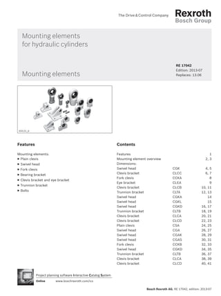
  • 1. Bosch Rexroth AG, RE 17042, edition: 2013-07 Project planning software Interactive Catalog System www.boschrexroth.com/icsOnline Mounting elements for hydraulic cylinders RE 17042  Edition: 2013-07 Replaces: 13.06Mounting elements Features Mounting elements: ▶ Plain clevis ▶ Swivel head ▶ Fork clevis ▶ Bearing bracket ▶ Clevis bracket and eye bracket ▶ Trunnion bracket ▶ Bolts Contents Features 1 Mounting element overview 2, 3 Dimensions: Swivel head CGK 4, 5 Clevis bracket CLCC 6, 7 Fork clevis CCKA 8 Eye bracket CLEA 9 Clevis bracket CLCB 10, 11 Trunnion bracket CLTA 12, 13 Swivel head CGKA 14 Swivel head CGKL 15 Swivel head CGKD 16, 17 Trunnion bracket CLTB 18, 19 Clevis bracket CLCA 20, 21 Clevis bracket CLCD 22, 23 Plain clevis CSA 24, 25 Swivel head CGA 26, 27 Swivel head CGAK 28, 29 Swivel head CGAS 30, 31 Fork clevis CCKB 32, 33 Swivel head CGKD 34, 35 Trunnion bracket CLTB 36, 37 Clevis bracket CLCA 38, 39 Clevis bracket CLCD 40, 41 H3121_d
  • 2. 2/44 Mounting elements Bosch Rexroth AG, RE 17042, edition: 2013-07 Mounting element overview Assembly (symbolic representation) Denomination / type To be attached to series Page Swivel head CGK ISO 12240-4 CD70/CG70 CD210/CG210 4, 5 Clevis bracket CLCC 6, 7 Fork clevis CCKA 8 Eye bracket CLEA 9 Clevis bracket (clampable) CLCB ISO 8133 DIN 24556 CDT3/CGT3/CST3 10, 11 Trunnion bracket CLTA 12, 13 Swivel head (clampable) CGKA ISO 8133 DIN 24555 14 Swivel head CGKL ISO 12240-4 CDL2 15 Swivel head (clampable) CGKD ISO 8132 16, 17 Trunnion bracket CLTB ISO 8132 18, 19 Clevis bracket (clampable) CLCA ISO 8132 form B 20, 21 Clevis bracket (clampable) CLCD ISO 8132 form A 22, 23
  • 3. Mounting elements 3/44 RE 17042, edition: 2013-07, Bosch Rexroth AG Assembly (symbolic representation) Denomination / type To be attached to series Page Plain clevis CSA CDH1/CGH1/CSH1 CDH3/CGH3/CSH3 24, 25 Swivel head CGA 26, 27 Swivel head (clampable) CGAK 28, 29 Swivel head (clampable) CGAS 30, 31 Fork clevis (clampable) CCKB ISO 8132 CDH2/CGH2/CSH2 CDM1/CGM1/CSM1 32, 33 Swivel head (clampable) CGKD ISO 8132 34, 35 Trunnion bracket CLTB ISO 8132 36, 37 Clevis bracket (clampable) CLCA ISO 8132 form B 38, 39 Clevis bracket (clampable) CLCD ISO 8132 form A 40, 41 Mounting element overview
  • 4. Z B1 2) ØD2 B2 50° D1 SW1 T1 L3 L2 L4 L1 D3 ØD4 ØD5 1) Z 4/44 Mounting elements Bosch Rexroth AG, RE 17042, edition: 2013-07 Series Type Material no. B1 -0,12 B2 D1 ØD2 h5 D3 max. ØD4 max. ØD5 max. CD70 / CG70 CD210 / CG210 ØAL ØAL ØMM 25 — — CGK 10 3) R900001653 9 7 M10 10 30 16 20 32 — — CGK 12 3) R900001327 10 8 M12 12 35 19 23 40 40 16 CGK 15 4) R900001328 12 10 M14 15 41 22 27 18 50 40 25 CGK 20 4) R900001329 16 13 M20x1,5 20 54 28 36 50 22 25 63 50 36 CGK 25 R900001330 20 17 M24x2 25 65 35 44 63 25 28 80 63 36 CGK 30 R900001331 22 19 M30x2 30 75 42 5245 80 36 — 80 45 CGK 35 R900012486 25 21 M36x3 35 84 47 60 100 80 56 CGK 40 R900001332 28 23 M39x3 40 94 52 67 125 100 45 CGK 45 R900001333 32 27 M42x3 45 104 58 72 150 100 50 CGK 50 R900001334 35 30 M45x3 50 114 62 77 70 125 50 56 200 125 63 CGK 60 R900001335 44 38 M52x3 60 137 70 90 63 150 90 70 — 150 80 CGK 80 R900001928 55 47 M64x4 80 182 95 112100 180 80 Dimensions: Swivel head CGK for series CD70/CG70 and CD210/CG210 (dimensions in mm) ISO 12240-4
  • 5. Mounting elements 5/44 RE 17042, edition: 2013-07, Bosch Rexroth AG Dimensions: Swivel head CGK for series CD70/CG70 and CD210/CG210 (dimensions in mm) Series Type L1 L2 L3 max. L4 min. T1 min. SW1 5) Z 5) m kg C0 6) kN Fadm 7) kN CD70 / CG70 CD210 / CG210 ØAL ØAL ØMM 25 — — CGK 10 3) 6,5 43 60 13 15 15 / 16 12° – 15° 0,07 17,6 5,8 32 — — CGK 12 3) 7 50 69 17 18 19 10° – 11° 0,1 24,5 8,1 40 40 16 CGK 15 4) 8 61 83 19 21 22 8° – 12° 0,16 36 11,9 18 50 40 25 CGK 20 4) 10 77 106 24 30 30 / 32 9° 0,34 60 19,8 50 22 25 63 50 36 CGK 25 12 94 128 30 36 36 7° 0,6 83 27,4 63 25 28 80 63 36 CGK 30 15 110 149 34 45 41 / 46 6° 0,9 110 36,345 80 36 — 80 45 CGK 35 15 125 169 40 60 50 6° 1,4 146 48,2 100 80 56 CGK 40 18 142 191 46 65 55 7° 2,0 180 59,4 125 100 45 CGK 45 20 145 199 50 65 60 / 65 7° 2,7 240 79,2 150 100 50 CGK 50 20 160 219 58 68 65 / 70 6° 3,5 290 95,7 70 125 50 56 200 125 63 CGK 60 20 175 246 73 70 75 6° 5,6 450 148,5 63 150 90 70 — 150 80 CGK 80 25 230 324 98 85 100 6° 13,1 750 247,5100 180 80 ØAL = piston Ø ØMM = piston rod Ø 1) Lubricating nipple, cone head form A according to DIN 71412 2) Bolt Ø m6 required 3) Cannot be re-lubricated 4) Can be re-lubricated via lubricating hole in housing 5) Dimensions may differ depending on the manufacturer 6) C0 = static load rating of the swivel head 7) Fadm = maximum admissible load on the swivel head during oscillatory or alternating loads Notice! Geometry and dimensions may differ depending on the manufacturer. In case of combination with other mount- ing elements, check the suitability.
  • 6. LE CM 1) CL1 CL2 FL R UD R UD ØHB b ER ØCK 6/44 Mounting elements Bosch Rexroth AG, RE 17042, edition: 2013-07 Dimensions: Clevis bracket CLCC for series CD70/CG70 and CD210/CG210 (dimensions in mm) Series Type Material no. ØCK H9 1) CL1 h16 CL2 max. CM A12 FL js12 CD70 / CG70 CD210 / CG210 ØAL 2) ØAL 3) ØAL ØMM ØAL 3) 25 — — — — CLCC 10 R900318440 10 25 37 9 35 32 25 — — — CLCC 12 R900318423 12 25 37 10 35 32 — — 40 40 40 16 40 CLCC 15 R900318468 15 35 48 12 45 18 50 50 40 25 50 CLCC 20 R900318469 20 50 64 16 58 50 22 63 25 63 80 50 36 63 CLCC 25 R900318470 25 60 74 20 75 63 25 100 28 80 125 63 36 — CLCC 30 R900318471 30 60 74 22 7545 80 36 — 150 80 45 80 CLCC 35 R900318472 35 70 93 25 90 100 — 80 56 100 CLCC 40 R900318473 40 70 93 28 90 125 200 100 45 125 CLCC 45 R900318481 45 110 133 32 125 150 — 100 50 150 CLCC 50 R900318482 50 110 133 35 125 70 125 50 56 200 — 125 63 180 CLCC 60 R900318483 60 125 148 44 155 90 150 63 70 — — 150 80 — CLCC 80 R900318477 80 140 163 55 130100 180 80 — — 180 90 — CLCC 81 R900318478 80 140 163 60 150 200 90 100 — — 180 125 — CLCC 90 R900318479 90 140 163 65 150 — — 200 140 — CLCC 100 R900318480 100 150 175 70 165 — — — 200 CLCC 70 R900318484 70 125 148 49 155 Suitable for swivel head type CGK… or CGA…
  • 7. Mounting elements 7/44 RE 17042, edition: 2013-07, Bosch Rexroth AG Dimensions: Clevis bracket CLCC for series CD70/CG70 and CD210/CG210 (dimensions in mm) ØAL = piston Ø ØMM = piston rod Ø 1) Bolt Ø m6 required (bolt and bolt lock are included in the scope of delivery) 2) When mounted on the piston rod with CGK… or CGA 3) When mounted on the cylinder base (mounting type "B") Series Type ØHB H13 ER max. LE min. UD max. R js14 b max. m kg CD70 / CG70 CD210 / CG210 ØAL 2) ØAL 3) ØAL ØMM ØAL 3) 25 — — — — CLCC 10 5,5 13 25 45 33 24 0,3 32 25 — — — CLCC 12 5,5 13 25 45 33 24 0,3 32 — — 40 40 40 16 40 CLCC 15 11 17 35 75 50 32 0,8 18 50 50 40 25 50 CLCC 20 13,5 22 42 90 65 40 1,8 50 22 63 25 63 80 50 36 63 CLCC 25 13,5 25 59 95 70 45 2,5 63 25 100 28 80 125 63 36 — CLCC 30 13,5 25 59 95 70 45 2,545 80 36 — 150 80 45 80 CLCC 35 17,5 35 68 130 95 65 6,0 100 — 80 56 100 CLCC 40 17,5 35 68 130 95 65 6,0 125 200 100 45 125 CLCC 45 26 46 100 180 135 85 15,0 150 — 100 50 150 CLCC 50 26 46 100 180 135 85 15,0 70 125 50 56 200 — 125 63 180 CLCC 60 33 66 125 225 170 125 28,0 90 150 63 70 — — 150 80 — CLCC 80 33 75 100 245 190 140 33,0100 180 80 — — 180 90 — CLCC 81 33 75 120 245 190 140 34,0 200 90 100 — — 180 125 — CLCC 90 33 75 120 245 190 140 35,0 — — 200 140 — CLCC 100 33 95 135 255 200 170 41,0 — — — 200 CLCC 70 33 80 125 225 170 145 28,0 Notice! Geometry and dimensions may differ depending on the manufacturer. In case of combination with other mount- ing elements, check the suitability.
  • 8. ØCK CM 1) CL1 CL2 KK LE CE MR b 8/44 Mounting elements Bosch Rexroth AG, RE 17042, edition: 2013-07 Dimensions: Fork clevis CCKA for series CD70/CG70 and CD210/CG210 (dimensions in mm) ØMM = piston rod Ø 1) Bolt Ø f7 required (bolt and bolt lock are included in the scope of delivery) 2) Only possible with thread design "C". Series Type 2) Material no. ØCK H7 1) CL1 h16 CL2 max. CM A12 CE js12 KK LE min. MR max. b max. m kg CD70 / CG70 CD210 / CG210 ØMM ØMM 16 16 CCKA 10 R900318486 12,7 44 56 20 38 M10x1,5 19 13 26 0,2 18 18 22 22 CCKA 16 R900318488 19,1 65 77 32,5 54 M16x1,5 26 19 38 1,0 25 25 CCKA 20 R900318487 19,1 65 77 32,5 54 M20x1,5 26 19 38 1,0 28 28 36 36 CCKA 26 R900318489 25,43 77 92 39 75 M26x1,5 34 26 52 2,4 45 45 CCKA 33 R900318491 34,95 100 118 51,5 95 M33x2 45 35 70 4,5 50 50 CCKA 39 R900318494 44,48 127 147 65 114 M39x2 57 45 90 8,5 56 56 63 63 CCKA 48 R900318496 50,83 127 147 65 140 M48x2 64 50 100 13,0 70 70 80 80 CCKA 58 R900541067 63,5 154 176 78 165 M58x2 76 65 130 23,0 90 90 CCKA 64 R900318498 76,23 154 176 78 172 M64x2 83 70 140 25,0 Notice! Geometry and dimensions may differ depending on the manufacturer. In case of combination with other mount- ing elements, check the suitability.
  • 9. ØCK R UD ØHB b ER LE EM 1) FL R UD 2) Mounting elements 9/44 RE 17042, edition: 2013-07, Bosch Rexroth AG Dimensions: Eye bracket CLEA for series CD70/CG70 and CD210/CG210 (dimensions in mm) ØAL = piston Ø ØMM = piston rod Ø 1) Lubricating nipple, cone head form A according to DIN 71412 2) Suitable for fork clevis type CCKA... 3) When mounted on the cylinder base (mounting type "G") 4) When mounted on the piston rod with CCKA... Series Type Material no. ØCK H7 2) EM h13 FL js12 ØHB H13 ER max. LE min. UD max. R js14 b m kg CD70 / CG70 CD210 / CG210 ØAL 3) ØMM 4) ØAL 3) ØMM 4) 32 16 40 16 CLEA 10 R900318516 12,7 20 28,5 11 13 18,5 63 41,5 24 0,4 40 50 18 18 63 80 22 50 22 CLEA 20 R900318518 19,1 32,5 47,5 13,5 22 31,5 89 65 40 1,6100 25 25 63 125 28 28 150 36 80 36 CLEA 26 R900318519 25,43 39 57 17,5 30 38 114 82,5 55 2,3 200 — 45 100 45 CLEA 33 R900318520 34,95 51,5 76 17,5 41 54 127 97 75 5,8 — 50 125 50 CLEA 39 R900318521 44,48 65 79,5 22 49 57 165 126 90 10,0 56 56 — 63 150 63 CLEA 48 R900318522 50,83 65 89 26 56 64 190 145,5 105 14,0 70 70 — 80 180 80 CLEA 58 R900318524 63,53 78 101,5 30 69 77 216 167 130 21,0 — 90 200 90 CLEA 64 R900318523 76,23 78 108 33 77 83 242 190,5 145 26,0 Notice! Geometry and dimensions may differ depending on the manufacturer. In case of combination with other mount- ing elements, check the suitability.
  • 10. CG ØCF ØHB CO LG GL 1)LO SR FM KC FO TA RE ØS 1 UJ SL CP KL LJ UK 10/44 Mounting elements Bosch Rexroth AG, RE 17042, edition: 2013-07 Dimensions: Clevis bracket CLCB - AB 5 (clampable) for series CDT3/CGT3/CST3 (dimensions in mm) ISO 8133 DIN 24556 Type Material no. Nominal force kN ØCF K7 1) CP h14 CG +0,1 +0,3 CO N9 FO js14 FM js11 GL js13 ØHB ØS CLCB 12 R900326960 8 12 30 10 10 16 40 46 9 15 CLCB 16 R900327372 12,5 16 40 14 16 18 50 61 11 18 CLCB 20 R900327373 20 20 50 16 16 20 55 64 14 3) 20 CLCB 25 R900326961 32 25 60 20 25 22 65 78 16 3) 24 CLCB 30 R900327374 50 30 70 22 25 24 85 97 18 3) 26 CLCB 40 R900327375 80 40 80 28 36 24 100 123 22 33 CLCB 50 R900327376 125 50 100 35 36 35 125 155 30 48 CLCB 60 R900327377 200 60 120 44 50 35 150 187 39 60 CLCB 80 R900327378 320 80 160 55 50 35 190 255 45 80 CLCB 100 R900327379 500 100 200 70 63 35 210 285 48 80
  • 11. Mounting elements 11/44 RE 17042, edition: 2013-07, Bosch Rexroth AG Dimensions: Clevis bracket CLCB - AB 5 (clampable) for series CDT3/CGT3/CST3 (dimensions in mm) Type KC +0,3 0 KL LG LJ LO RE js13 SL SR max. TA js13 UJ UK m 2) kg CLCB 12 3,3 8 28 29 56 55 40 12 40 75 60 0,6 CLCB 16 4,3 8 37 38 74 70 50 16 55 95 80 1,3 CLCB 20 4,3 10 39 40 80 85 62 20 58 120 90 2,1 CLCB 25 5,4 10 48 49 98 100 72 25 70 140 110 3,2 CLCB 30 5,4 13 62 63 120 115 85 30 90 160 135 6,5 CLCB 40 8,4 16 72 73 148 135 100 40 120 190 170 12,0 CLCB 50 8,4 19 90 92 190 170 122 50 145 240 215 23,0 CLCB 60 11,4 20 108 110 225 200 145 60 185 270 260 37,0 CLCB 80 11,4 26 140 142 295 240 190 80 260 320 340 79,0 CLCB 100 12,4 30 150 152 335 300 235 100 300 400 400 140,0 1) Bolt Ø h6 required, suitable for swivel head CGKA... (bolt and bolt lock are included in the scope of delivery) 2) m = weight of clevis bracket in kg 3) Dimensions may differ from the standard depending on the manufacturer Notice! Geometry and dimensions may differ depending on the manufacturer. In case of combination with other mount- ing elements, check the suitability.
  • 12. 2) FS NH "A" "A" l1 ØCR KC CO TH UL FN FK l2 1) 1) ØHB l3x45 12/44 Mounting elements Bosch Rexroth AG, RE 17042, edition: 2013-07 Dimensions: Trunnion bracket CLTA - AT 4 for series CDT3/CGT3/CST3 (dimensions in mm) CLTA 12-20 or ØAL = piston Ø 1) Lubricating nipple, cone form A according to DIN 71412 2) Inside 3) Dimensions may differ depending on the manufacturer 4) Nominal force applies to applications in pairs 5) m = weight per pair in kg, brackets are delivered in pairs Notice! Geometry and dimensions may differ depending on the manufacturer. In case of combination with other mount- ing elements, check the suitability. Series CDT3 / CGT3 / CST3 ØAL Type Material no. Nominal force kN 4) ØCR H7 CO N9 FK js12 FN max. FS js14 ØHB H13 KC +0,3 0 NH max. TH js14 UL max. l1 l2 l3 m 5 ) kg 25 CLTA 12 R901071355 8 12 10 38 55 8 9 3,3 17 3) 40 63 25 25 1 0,5 32 CLTA 16 R901071364 12,5 16 16 45 65 10 11 4,3 21 50 80 30 30 1 0,9 40 CLTA 20 R901071365 20 20 16 55 80 10 11 4,3 21 60 90 40 38 1,5 1,35
  • 13. FS NH "A" "A" l1 ØCR KC CO TH UL FN FK l2 1) ØHB 1) 2) l3x45° Mounting elements 13/44 RE 17042, edition: 2013-07, Bosch Rexroth AG CLTA 25-100 ØAL = piston Ø 1) Lubricating nipple, cone form A according to DIN 71412 2) Inside 3) Dimensions may differ depending on the manufacturer 4) Nominal force applies to applications in pairs 5) m = weight per pair in kg, brackets are delivered in pairs Notice! Geometry and dimensions may differ depending on the manufacturer. In case of combination with other mount- ing elements, check the suitability. or Dimensions: Trunnion bracket CLTA - AT 4 for series CDT3/CGT3/CST3 (dimensions in mm) Series CDT3 / CGT3 / CST3 ØAL Type Material no. Nominal force kN 4) ØCR H7 CO N9 FK js12 FN max. FS js14 ØHB H13 KC +0,3 0 NH max. TH js14 UL max. l1 l2 l3 m 5) kg 50 CLTA 25 R901071368 32 25 25 65 90 12 14 3) 5,4 26 80 110 56 45 1,5 2,4 63 CLTA 32 R901071377 50 32 25 75 110 15 18 3) 5,4 33 110 150 70 52 2 5,0 80 CLTA 40 R901071380 80 40 36 95 140 16 22 8,4 41 125 170 88 60 2,5 8,5 100 CLTA 50 R901071385 125 50 36 105 150 20 26 8,4 51 160 210 90 72 2,5 15 125 CLTA 63 R901071395 200 63 50 125 195 25 33 11,4 61 200 265 136 87 3 30 160 CLTA 80 R901071398 320 80 50 150 230 31 39 11,4 81 250 325 160 112 3,5 59 200 CLTA 100 R901071400 500 100 63 200 300 42 52 12,4 101 320 410 200 150 4,5 131
  • 14. EU EN KK C ØCN Øb AX 3° 3° 2) 1) CH LF MA 14/44 Mounting elements Bosch Rexroth AG, RE 17042, edition: 2013-07 Dimensions: Swivel head CGKA - AP 6 (clampable) for series CDT3/CGT3/CST3 (dimensions in mm) ISO 8133 DIN 24555 Type Material no. KK AX min. Øb C max. CH js13 ØCN 2) EN EU max. LF min. MA 7) Nm m 8) kg C0 9) (head) kN Fadm 10) kN CGKA 12 3) R900327186 M10x1,25 15 17 40 42 12 –0,008 10 –0,12 8 16 9,5 0,15 17 6,3 CGKA 16 4) R900327192 M12x1,25 17 21 45 48 16 –0,008 14 –0,12 11 20 9,5 0,25 28,5 10,5 CGKA 20 4) R900306874 M14x1,5 19 25 55 58 20 –0,012 16 –0,12 13 25 23 0,43 42,5 15,7 CGKA 25 R900327191 M16x1,5 23 30 65 68 25 –0,012 20 –0,12 17 30 23 0,73 67 24,7 CGKA 30 R900327187 M20x1,5 29 36 80 85 30 –0,012 22 –0,12 19 35 46 1,3 108 39,9 CGKA 40 R900327188 M27x2 37 45 100 105 40 –0,012 28 –0,12 23 45 46 2,3 156 57,6 CGKA 50 R900327368 M33x2 46 55 125 130 50 –0,012 35 –0,12 30 58 80 4,4 245 90,4 CGKA 60 R900327369 M42x2 57 68 160 150 60 –0,012 44 –0,12 38 68 195 8,4 380 140,2 CGKA 80 R900327370 M48x2 64 90 205 185 80 –0,015 55 –0,15 47 82 6) 385 15,6 585 215,9 CGKA 100 R900327371 M64x3 86 110 240 240 100 –0,02 70 –0,2 57 116 660 28 865 319,2 CGKD 100 5) R900322030 M80x3 96 110 210 210 100 H7 100 h12 84 98 385 28 1060 391,1 CGKD 125 5) R900322026 M100x3 113 135 262 260 125 H7 125 h12 102 120 385 43 1200 442,8 1) Lubricating nipple, cone head form A according to DIN 71412 2) Bolt Ø h6 required 3) Cannot be re-lubricated 4) Can be re-lubricated via lubricating hole 5) Swivel head according to ISO 8132, bolt Ø m6 required 6) Dimensions may differ from the standard depending on the manufacturer 7) MA = tightening torque The swivel head must always be screwed against the shoulder of the piston rod. Afterwards, the clamping screws must be tightened with the specified tightening torque. 8) m = weight of swivel head in kg 9) C0 = static load rating of the swivel head 10) Fadm = maximum admissible load on the swivel head during oscillatory or alternating loads Notice! Geometry and dimensions may differ depending on the manufacturer. In case of combination with other mount- ing elements, check the suitability.
  • 15. NV CP KK BA KW LF EU EN C 10 CN 10 Mounting elements 15/44 RE 17042, edition: 2013-07, Bosch Rexroth AG Dimensions: Swivel head CGKL for series CDL2 (dimensions in mm) Series CDL2 Type Material no. KK BA min. C ØCN -0,008 CP max. EN h12 EU max. KW LF min. NV m 1) kg C0 2) kN Fadm 3) kN ØAL ØMM 25 14 CGKL 10 3712500031 M10 26 29 10 48 9 7,5 5 15 16 0,1 22 8,1 32 18 CGKL 12 3713200031 M12 28 34 12 54 10 8,5 6 18 18 0,1 30,4 11,2 ISO 12240-4 ØAL = piston Ø ØMM = piston rod Ø 1) m = weight of swivel head in kg 2) C0 = static load rating of the swivel head in kN 3) Fadm = maximum admissible load on the swivel head during oscillatory or alternating loads Notice! Geometry and dimensions may differ depending on the manufacturer. In case of combination with other mount- ing elements, check the suitability.
  • 16. EN EU CH LF 1) KK AV N 2) EF MA 3) 4 4 CN 16/44 Mounting elements Bosch Rexroth AG, RE 17042, edition: 2013-07 Dimensions: Swivel head CGKD (clampable) for series CDL2 (dimensions in mm) ISO 8132 Series CDL2 Type Material no. Nominal force kN AV min. N max. CH js13 EF max. ØCN H7 2) EN h12 EU max. ØAL ØMM 40 22 CGKD 20 R900308576 20 23 28 52 25 20 20 17,5 40 25 CGKD 25 R900323332 32 29 31 65 32 25 25 22 50 28 50 32 CGKD 32 R900322049 50 37 38 80 40 32 32 28 63 36 63 40 CGKD 40 R900322029 80 46 47 97 50 40 40 34 80 45 80 50 CGKD 50 R900322719 125 57 58 120 63 50 50 42 100 56 100 63 CGKD 63 R900322028 200 64 70 140 72,5 63 63 53,5 125 70 125 80 CGKD 80 R900322700 320 86 91 180 92 80 80 68 160 100 CGKD 100 R900322030 500 96 110 210 114 100 100 85,5 200 125 CGKD 125 R900322026 800 113 135 260 160 125 125 105
  • 17. Mounting elements 17/44 RE 17042, edition: 2013-07, Bosch Rexroth AG ØAL = piston Ø ØMM = piston rod Ø 1) Lubricating nipple, cone head form A according to DIN 71412 2) Bolt Ø m6 required 3) MA = tightening torque in Nm The swivel head must always be screwed against the shoulder of the piston rod. Afterwards, the clamping screws must be tightened with the specified tightening torque 4) m = weight of swivel head in kg 5) C0 = static load rating of the swivel head in kN 6) Fadm = maximum admissible load on the swivel head in kN during oscillatory or alternating loads Dimensions: Swivel head CGKD (clampable) for series CDL2 (dimensions in mm) Notice! Geometry and dimensions may differ depending on the manufacturer. In case of combination with other mount- ing elements, check the suitability. Series CDL2 Type KK LF min. Clamping screws ISO 4762-10.9 MA 3) Nm m 4) kg C0 5) kN Fadm 6) kN ØAL ØMM 40 22 CGKD 20 M16x1,5 20,5 M8x20 25 0,35 48 17,7 40 25 CGKD 25 M20x1,5 25,5 M8x20 30 0,65 78 28,8 50 28 50 32 CGKD 32 M27x2 30 M10x25 59 1,15 114 42,1 63 36 63 40 CGKD 40 M33x2 39 M10x30 59 2,1 204 75,3 80 45 80 50 CGKD 50 M42x2 47 M12x35 100 4 310 114,4 100 56 100 63 CGKD 63 M48x2 58 M16x40 250 7,2 430 158,7 125 70 125 80 CGKD 80 M64x3 74 M20x50 490 15 695 265,5 160 100 CGKD 100 M80x3 94 M24x60 840 25,5 1060 391,1 200 125 CGKD 125 M100x3 116 M24x70 840 52,5 1430 527,7
  • 18. "A" l1 ØCR KC CO TH UL FN FK l2 1) ØHB 2) FS NH "A" l3x45 "A" l1 ØCR KC CO TH UL FN FK l2 1) ØHB 18/44 Mounting elements Bosch Rexroth AG, RE 17042, edition: 2013-07 CLTB 12 ... 20 Dimensions: Trunnion bracket CLTB for series CDL2 (dimensions in mm) CLTB 25 ... 80 Series CDL2 Type 3) Material no. Nominal force kN 4) ØCR H7 CO N9 FK js12 FN max. FS js14 ØHB H13 ØAL ØMM 25 14 CLTB 12 R900772607 8 12 10 34 50 8 9 32 18 CLTB 16 R900772608 12,5 16 16 40 60 10 11 40 22 CLTB 20 R900772609 20 20 16 45 70 10 11 40 25 CLTB 25 R900772610 32 25 25 55 80 12 13,5 50 28 50 32 CLTB 32 R900772611 50 32 25 65 100 15 17,5 63 36 63 40 CLTB 40 R900772612 80 40 36 76 120 16 22 80 45 80 50 CLTB 50 R900772613 125 50 36 95 140 20 26 100 56 100 63 CLTB 63 R900772614 200 63 50 112 180 25 33 125 70 125 80 CLTB 80 R900772615 320 80 50 140 220 31 39 ISO 8132
  • 19. Mounting elements 19/44 RE 17042, edition: 2013-07, Bosch Rexroth AG Notice! Geometry and dimensions may differ depending on the manufacturer. In case of combination with other mount- ing elements, check the suitability. The trunnion brackets are suitable for mounting type MT4. Dimensions: Trunnion bracket CLTB for series CDL2 (dimensions in mm) ØAL = piston Ø ØMM = piston rod Ø 1) Lubricating nipple, cone head form A according to DIN 71412 2) Contact surface trunnion (inside) 3) Bearing blocks are always supplied in pairs 4) Nominal force applies to applications in pairs 5) m = weight of trunnion bracket in kg (specified per pair) Series CDL2 Type 3) KC +0,3 l1 l2 l3 NH max. TH js14 UL max. m 5) kg ØAL ØMM 25 14 CLTB 12 3,3 25 25 1 17 40 63 0,4 32 18 CLTB 16 4,3 30 30 1 21 50 80 0,85 40 22 CLTB 20 4,3 40 38 1,5 21 60 90 1,2 40 25 CLTB 25 5,4 56 45 1,5 26 80 110 2,1 50 28 50 32 CLTB 32 5,4 70 52 2 33 110 150 4,55 63 36 63 40 CLTB 40 8,4 88 60 2,5 41 125 170 7,3 80 45 80 50 CLTB 50 8,4 100 75 2,5 51 160 210 14,5 100 56 100 63 CLTB 63 11,4 130 85 3 61 200 265 23,1 125 70 125 80 CLTB 80 11,4 160 112 3,5 81 250 325 52,3
  • 20. 1) ØS ØHB COFOFG KC RG UX MR 1 ØCK SL CL KL CM RF UK LE FL 20/44 Mounting elements Bosch Rexroth AG, RE 17042, edition: 2013-07 Dimensions: Clevis bracket CLCA (clampable) for series CDL2 (dimensions in mm) ISO 8132, form B Series CDL2 Type Material no. Nominal force kN ØCK H9 1) CL h16 CM A12 CO N9 FG js14 FL js12 FO js14 ØHB H13 ØAL ØMM 25 14 CLCA 10 2) 3) 5 10 24 10 8 2 32 10 6,6 32 18 CLCA 12 2) R900542861 8 12 28 12 10 2 34 10 9 40 22 CLCA 20 R900542863 20 20 45 20 16 7,5 45 10 11 40 25 CLCA 25 R900542864 32 25 56 25 25 10 55 10 13,5 50 28 50 32 CLCA 32 R900542865 50 32 70 32 25 14,5 65 6 17,5 63 36 63 40 CLCA 40 R900542866 80 40 90 40 36 17,5 76 6 22 80 45 80 50 CLCA 50 R900542867 125 50 110 50 36 25 95 0 26 100 56 100 63 CLCA 63 R900542868 200 63 140 63 50 33 112 0 33 125 70 125 80 CLCA 80 R900542869 320 80 170 80 50 45 140 0 39 160 100 CLCA 100 3) 500 100 210 100 63 52,5 180 0 52 200 125 CLCA 125 3) 800 125 270 125 80 75 230 0 52
  • 21. Mounting elements 21/44 RE 17042, edition: 2013-07, Bosch Rexroth AG Series CDL2 Type KC +0,3 KL LE min. MR max. RF js14 RG js14 ØS SL UK max. UX max. m 4) kg ØAL ØMM 25 14 CLCA 10 2) 3,3 8 22 10 39 44 11 34 56 60 0,33 32 18 CLCA 12 2) 3,3 8 22 12 52 45 15 38 72 65 0,45 40 22 CLCA 20 4,3 10 30 20 75 70 18 58 100 95 1,5 40 25 CLCA 25 5,4 10 37 25 90 85 20 69 120 115 3 50 28 50 32 CLCA 32 5,4 13 43 32 110 110 26 87 145 145 4,5 63 36 63 40 CLCA 40 8,4 16 52 40 140 125 33 110 185 170 8,5 80 45 80 50 CLCA 50 8,4 19 65 50 165 150 40 133 215 200 13,5 100 56 100 63 CLCA 63 11,4 20 75 63 210 170 48 164 270 230 23,4 125 70 125 80 CLCA 80 11,4 26 95 80 250 210 57 202 320 280 38,5 160 100 CLCA 100 12,4 30 120 100 315 250 76 246 405 345 99,2 200 125 CLCA 125 15,4 32 170 125 365 350 76 310 455 450 174,1 Dimensions: Clevis bracket CLCA (clampable) for series CDL2 (dimensions in mm) Notice! Geometry and dimensions may differ depending on the manufacturer. In case of combination with other mount- ing elements, check the suitability. The clevis brackets are suitable for mounting type MP5 and for mounting on the swivel head. ØAL = piston Ø ØMM = piston rod Ø 1) Bolt Ø m6 required (bolt and bolt lock are included in the scope of delivery and are not mounted upon delivery) 2) 2 washers for mounting required ▶ for CLCA 10: Washer DIN 988 10x16x0.5 Material no. R900061310 ▶ for CLCA 12: Washer DIN 988 12x18x1 Material no. R900006948 3) Upon request 4) m = weight of clevis bracket in kg
  • 22. 1) SL CL KL CM UR RC ØCK FL LE UH TB ØS ØHB MR 1 22/44 Mounting elements Bosch Rexroth AG, RE 17042, edition: 2013-07 Dimensions: Clevis bracket CLCD (clampable) for series CDL2 (dimensions in mm) ISO 8132, form A Series CDL2 Type Material no. Nominal force kN ØCK H9 1) CL h16 CM A12 FL js12 ØHB H13 KL LE min. ØAL ØMM 25 14 CLCD 10 2) 3) 5 10 24 10 32 6,6 8 22 32 18 CLCD 12 2) R900542879 8 12 28 12 34 9 8 22 40 22 CLCD 20 R900542881 20 20 45 20 45 11 10 30 40 25 CLCD 25 R900542882 32 25 56 25 55 13,5 10 37 50 28 50 32 CLCD 32 R900542883 50 32 70 32 65 17,5 13 43 63 36 63 40 CLCD 40 R900542884 80 40 90 40 76 22 16 52 80 45 80 50 CLCD 50 R900542885 125 50 110 50 95 26 19 65 100 56 100 63 CLCD 63 R900542886 200 63 140 63 112 33 20 75 125 70 125 80 CLCD 80 R900542887 320 80 170 80 140 39 26 95 160 100 CLCD 100 3) 500 100 210 100 180 45 30 120 200 125 CLCD 125 3) 800 125 270 125 230 52 32 170
  • 23. Mounting elements 23/44 RE 17042, edition: 2013-07, Bosch Rexroth AG Dimensions: Clevis bracket CLCD (clampable) for series CDL2 (dimensions in mm) Notice! Geometry and dimensions may differ depending on the manufacturer. In case of combination with other mount- ing elements, check the suitability. The clevis brackets are suitable for mounting type MP5 and for mounting on the swivel head. Series CDL2 Type MR max. RC js14 ØS SL TB js14 UR max. UH max. m 3) kg ØAL ØMM 25 14 CLCD 10 2) 10 17 11 34 42 33 60 0,27 32 18 CLCD 12 2) 12 20 15 38 50 40 70 0,35 40 22 CLCD 20 20 32 18 58 75 58 98 0,95 40 25 CLCD 25 25 40 20 69 85 70 113 1,9 50 28 50 32 CLCD 32 32 50 26 87 110 85 143 3 63 36 63 40 CLCD 40 40 65 33 110 130 108 170 5,5 80 45 80 50 CLCD 50 50 80 40 133 170 130 220 10,6 100 56 100 63 CLCD 63 63 100 48 164 210 160 270 17 125 70 125 80 CLCD 80 80 125 57 202 250 210 320 32 160 100 CLCD 100 100 160 66 246 315 260 400 74 200 125 CLCD 125 125 200 76 310 385 320 470 129 ØAL = piston Ø ØMM = piston rod Ø 1) Bolt Ø m6 required (bolt and bolt lock are included in the scope of delivery and are not mounted upon delivery) 2) 2 washers for mounting required ▶ for CLCA 10: Washer DIN 988 10x16x0.5 Material no. R900061310 ▶ for CLCA 12: Washer DIN 988 12x18x1 Material no. R900006948 3) Upon request 4) m = weight of clevis bracket in kg
  • 24. 1) EM ØCK KK2) Øb AW LE CA L1 C 24/44 Mounting elements Bosch Rexroth AG, RE 17042, edition: 2013-07 Dimensions: Plain clevis CSA for series CDH1/CGH1/CSH1 and CDH3/CGH3/CSH3 (dimension in mm) AL-Ø 40 … 200 mm Series Type Material no. AW Øb C CA ØCK H11 EM -0,4 CDH1 / CGH1 / CSH1 ØAL CDH3 / CGH3 / CSH3 ØAL 40 — CSA 16 R900303150 17 28 56 50 25 23 50 40 CSA 22 R900303151 23 34 64 60 30 28 63 50 CSA 28 R900303152 29 44 78 70 35 30 80 63 CSA 35 R900303153 36 55 94 85 40 35 100 80 CSA 45 R900303154 46 70 116 105 50 40 125 100 CSA 58 R900303155 59 87 130 130 60 50 140 125 CSA 65 R900303156 66 93 154 150 70 55 160 140 CSA 80 R900303157 81 125 176 170 80 60 180 160 CSA100 R900303158 101 143 206 210 90 65 200 180 CSA110 R900303159 111 153 230 235 100 70 — 200 CSA120 R900303160 125 176 265 265 110 80
  • 25. Mounting elements 25/44 RE 17042, edition: 2013-07, Bosch Rexroth AG ØAL = piston Ø 1) Lubricating nipple, cone head form A according to DIN 71412 2) The plain clevis must always be screwed against the shoulder of the piston rod 3) m = weight of plain clevis in kg 4) C0 = static load rating of the plain clevis 5) Fadm = maximum admissible load on the plain clevis during oscillatory or alternating loads Notice! The specified dimensions are maximum values and may differ depending on the manufacturer. The following values are excluded: CA, CK, EM, KK Series Type KK LE L1 m 3) kg C0 4) kN Fadm 5) kN CDH1 / CGH1 / CSH1 ØAL CDH3 / CGH3 / CSH3 ØAL 40 — CSA 16 M16x1,5 25 80 0,43 72 25,9 50 40 CSA 22 M22x1,5 30 94 0,7 106 38,2 63 50 CSA 28 M28x1,5 40 112 1,1 153 55,1 80 63 CSA 35 M35x1,5 45 135 2,0 250 90,0 100 80 CSA 45 M45x1,5 55 168 3,3 365 131,4 125 100 CSA 58 M58x1,5 65 200 5,5 400 144,0 140 125 CSA 65 M65x1,5 75 232 8,6 540 194,4 160 140 CSA 80 M80x2 80 265 12,2 670 241,2 180 160 CSA100 M100x2 90 323 21,5 980 352,8 200 180 CSA110 M110x2 105 360 27,5 1120 403,2 — 200 CSA120 M120x2 115 407,5 40,7 1700 612,0 Dimensions: Plain clevis CSA for series CDH1/CGH1/CSH1 and CDH3/CGH3/CSH3 (dimension in mm)
  • 26. EU EN ØCN AX KK3) Øb Z Z LF CH L1 C 1) 2) 26/44 Mounting elements Bosch Rexroth AG, RE 17042, edition: 2013-07 Dimensions: Swivel head CGA for series CDH1/CGH1/CSH1 and CDH3/CGH3/CSH3 (dimensions in mm) AL-Ø 40 … 280 mm Series Type Material no. AX min. Øb max. C CH ØCN 2) EN EU -0,4 CDH1 / CGH1 / CSH1 ØAL CDH3 / CGH3 / CSH3 ØAL 40 — CGA 16 R900303125 17 26 56 50 25–0,010 20–0,12 23 50 40 CGA 22 R900303126 23 33 64 60 30–0,010 22–0,12 28 63 50 CGA 28 R900303127 29 41 78 70 35–0,012 25–0,12 30 80 63 CGA 35 R900303128 36 50 94 85 40–0,012 28–0,12 35 100 80 CGA 45 R900303129 46 62 116 105 50–0,012 35–0,12 40 125 100 CGA 58 R900303130 59 76 130 130 60–0,015 44–0,15 50 140 125 CGA 65 R900303131 66 87 154 150 70–0,015 49–0,15 55 160 140 CGA 80 R900303132 81 106 176 170 80–0,015 55–0,15 60 180 160 CGA100 R900303133 101 125 206 210 90-0,020 60–0,20 65 200 180 CGA110 R900303134 111 139 230 235 100–0,020 70–0,20 70 220 200 CGA120 R900303135 125 153 265 265 110–0,020 70–0,20 80 250 220 CGA120 R900303135 125 153 265 265 110–0,020 70–0,20 80 280 250 CGA130 R900303136 135 173 340 310 120–0,020 85–0,20 90
  • 27. Mounting elements 27/44 RE 17042, edition: 2013-07, Bosch Rexroth AG ØAL = piston Ø 1) Lubricating nipple, cone head form A according to DIN 71412 2) Bolt Ø m6 required; Bolt Ø j6 required with maintenance-free spherical bearing 3) The swivel head must always be screwed against the shoulder of the piston rod 4) m = weight of swivel head in kg 5) C0 = static load rating of the swivel head 6) Fadm = maximum admissible load on the swivel head during oscillatory or alternating loads Dimensions: Swivel head CGA for series CDH1/CGH1/CSH1 and CDH3/CGH3/CSH3 (dimensions in mm) AL-Ø 40 … 280 mm Notice! The specified dimensions are maximum values and may differ depending on the manufacturer. The following values are excluded: CH, CN, EN, EU, KK Series Type KK L1 LF min. Z m 4) kg C0 5) kN Fadm 6) kN CDH1 / CGH1 / CSH1 ØAL CDH3 / CGH3 / CSH3 ØAL 40 — CGA 16 M16x1,5 80 28 7° 0,43 72 25,9 50 40 CGA 22 M22x1,5 94 30 6° 0,7 106 38,2 63 50 CGA 28 M28x1,5 112 38 6° 1,1 153 55,1 80 63 CGA 35 M35x1,5 135 45 7° 2,0 250 90,0 100 80 CGA 45 M45x1,5 168 55 6° 3,3 365 131,4 125 100 CGA 58 M58x1,5 200 65 6° 5,5 400 144,0 140 125 CGA 65 M65x1,5 232 75 6° 8,6 540 194,4 160 140 CGA 80 M80x2 265 80 6° 12,2 670 241,2 180 160 CGA100 M100x2 323 90 5° 21,5 980 352,8 200 180 CGA110 M110x2 360 105 7° 27,5 1120 403,2 220 200 CGA120 M120x3 407,5 115 6° 40,7 1700 612,0 250 220 CGA120 M120x3 407,5 115 6° 40,7 1700 612,0 280 250 CGA130 M130x3 490 140 6° 76,4 2900 1044,0
  • 28. EU EN ØCN AX KK Øb Z Z LF CH L1 C 1) L2 MA 3) 2) 28/44 Mounting elements Bosch Rexroth AG, RE 17042, edition: 2013-07 Dimensions: Swivel head CGAK (clampable) for series CDH1/CGH1/CSH1 and CDH3/CGH3/CSH3 (dimensions in mm) Series Type Material no. AX min. Øb max. C CH ØCN 2) EN EU -0,4 KK CDH1 / CGH1 / CSH1 ØAL CDH3 / CGH3 / CSH3 ØAL 40 — CGAK 16 R900303162 17 26 56 50 25–0,010 20–0,12 23 M16x1,5 50 40 CGAK 22 R900303163 23 33 64 60 30–0,010 22–0,12 28 M22x1,5 63 50 CGAK 28 R900303164 29 41 78 70 35–0,012 25–0,12 30 M28x1,5 80 63 CGAK 35 R900303165 36 50 94 85 40–0,012 28–0,12 35 M35x1,5 100 80 CGAK 45 R900303166 46 62 116 105 50–0,012 35–0,12 40 M45x1,5 125 100 CGAK 58 R900303167 59 76 130 130 60–0,015 44–0,15 50 M58x1,5 140 125 CGAK 65 R900303168 66 87 154 150 70–0,015 49–0,15 55 M65x1,5 160 140 CGAK 80 R900303169 81 106 176 170 80–0,015 55–0,15 60 M80x2 180 160 CGAK100 R900321655 101 125 206 210 90–0,020 60–0,20 65 M100x2 200 180 CGAK110 R900321691 111 139 231 235 100–0,020 70–0,20 70 M110x2 220 200 CGAK120 R900321621 125 155 266 265 110–0,020 70–0,20 80 M120x3 250 220 CGAK120 R900321621 125 153 265 265 110–0,020 70–0,20 80 M120x3 280 250 CGAK130 R900322015 135 173 340 310 120–0,020 85–0,20 90 M130x3 AL-Ø 40 … 280 mm
  • 29. Mounting elements 29/44 RE 17042, edition: 2013-07, Bosch Rexroth AG Dimensions: Swivel head CGAK (clampable) for series CDH1/CGH1/CSH1 and CDH3/CGH3/CSH3 (dimensions in mm) ØAL = piston Ø 1) Lubricating nipple, cone head form A according to DIN 71412 2) Bolt Ø m6 required; Bolt Ø j6 required with maintenance-free spherical bearing 3) MA = tightening torque The swivel head must always be screwed against the shoulder of the piston rod. Afterwards, the clamping screws must be tightened with the specified tightening torque. 4) m = weight of swivel head in kg 5) C0 = static load rating of the swivel head 6) Fadm = maximum admissible load on the swivel head during oscillatory or alternating loads Series Type L1 L2 max. LF Z Clamping screws ISO 4762-10.9 MA 3) Nm m 4) kg C0 5) kN Fadm 6) kN CDH1 / CGH1 / CSH1 ØAL CDH3 / CGH3 / CSH3 ØAL 40 — CGAK 16 80 24 28 7° M8 30 0,43 72 25,9 50 40 CGAK 22 94 26 30 6° M8 30 0,7 106 38,2 63 50 CGAK 28 112 34 38 6° M10 54 1,1 153 55,1 80 63 CGAK 35 135 39 45 7° M10 59 2,0 250 90,0 100 80 CGAK 45 168 46 55 6° M12 100 3,3 365 131,4 125 100 CGAK 58 200 61 65 6° M16 250 5,5 400 144,0 140 125 CGAK 65 232 66 75 6° M16 250 8,6 540 194,4 160 140 CGAK 80 265 81 80 6° M20 490 12,2 670 241,2 180 160 CGAK100 323 91 90 5° M20 490 21,5 980 352,8 200 180 CGAK110 360 101 105 7° M24 840 27,5 1120 403,2 220 200 CGAK120 407,5 111 115 6° M24 840 40,7 1700 612,0 250 220 CGAK120 407,5 111 115 6° M24 840 40,7 1700 612,0 280 250 CGAK130 490 129 140 6° M24 840 76,4 2900 1044,0 Notice! The specified dimensions are maximum values and may differ depending on the manufacturer. The following values are excluded: CH, CN, EN, EU, KK
  • 30. EU EN ØCN AX KK3) Øb Z Z LF CH L1 C 1) L2 MA 3) 2) 30/44 Mounting elements Bosch Rexroth AG, RE 17042, edition: 2013-07 Dimensions: Swivel head CGAS (clampable) for series CDH1/CGH1/CSH1 and CDH3/CGH3/CSH3 (dimensions in mm) Series Type Material no. AX min. Øb max. C max. CH ØCN 2) EN EU -0,4 KK CDH1 / CGH1 / CSH1 ØAL CDH3 / CGH3 / CSH3 ØAL 40 — CGAS 25 R900303137 30 28 56 65 25–0,010 20–0,12 23 M18x2 50 40 CGAS 30 R900303138 35 34 64 75 30–0,010 22–0,12 28 M24x2 63 50 CGAS 35 R900303139 46 46 78 90 35–0,012 25–0,12 30 M30x2 80 63 CGAS 40 R900303140 56 57 94 105 40–0,012 28–0,12 35 M39x3 100 80 CGAS 50 R900303141 76 70 116 135 50–0,012 35–0,12 40 M50x3 125 100 CGAS 60 R900303142 96 87 130 170 60–0,015 44–0,15 50 M64x3 140 125 CGAS 70 R900303143 112 111 154 195 70–0,015 49–0,15 55 M80x3 160 140 CGAS 80 R900303144 122 129 176 210 80–0,015 55–0,15 60 M90x3 180 160 CGAS 90 R900303145 142 153 211 250 90–0,020 60–0,20 65 M100x3 200 180 CGAS100 R900303146 152 170 230 275 100–0,020 70–0,20 70 M110x4 220 200 CGAS110 R900303147 162 180 264 300 110–0,020 70–0,20 80 M120x4 250 220 CGAS110 R900303147 162 180 264 300 110–0,020 70–0,20 80 M120x4 280 250 CGAS120 R900303148 192 210 340 360 120–0,020 85–0,20 90 M150x4 320 280 CGAS140 R900317314 210 230 380 420 140–0,025 90–0,25 110 M160x4 — 320 CGAS160 R900303149 221 260 480 460 160–0,025 105–0,25 110 M180x4
  • 31. Mounting elements 31/44 RE 17042, edition: 2013-07, Bosch Rexroth AG ØAL = piston Ø 1) Lubricating nipple, cone head form A according to DIN 71412 2) Bolt Ø m6 required; Bolt Ø j6 required with maintenance-free spherical bearing 3) Dimensions may differ depending on the manufacturer 4) MA = tightening torque The swivel head must always be screwed against the shoulder of the piston rod. Afterwards, the clamping screws must be tightened with the specified tightening torque. 5) m = weight of swivel head in kg 6) C0 = static load rating of the swivel head 7) Fadm = maximum admissible load on the swivel head during oscillatory or alternating loads Series Type L1 max. L2 max. LF min. Z 3) Clamping screws ISO 4762-10.9 MA 4 ) Nm m 5) kg C0 6) kN Fadm 7) kN CDH1 / CGH1 / CSH1 ØAL CDH3 / CGH3 / CSH3 ØAL 40 — CGAS 25 95 24 25 7-8° M8 30 0,65 82 27,1 50 40 CGAS 30 109 28 30 6-7° M8 30 1,0 122 40,3 63 50 CGAS 35 132 36 40 6-7° M10 59 1,5 177 58,4 80 63 CGAS 40 155 39 44 7° M12 100 2,4 287 94,7 100 80 CGAS 50 198 45 55 6-7° M12 100 4,8 422 139,3 125 100 CGAS 60 240 59 65 6-7° M16 250 8,6 522 172,3 140 125 CGAS 70 279 70 75 6° M16 250 12,2 707 233,3 160 140 CGAS 80 305 85 80 6° M20 490 18,4 870 287,1 180 160 CGAS 90 366 91 90 5° M20 490 31,6 1284 423,7 200 180 CGAS100 400 95 105 7° M20 490 34 1460 481,8 220 200 CGAS110 443 106 115 6° M24 840 44 2024 667,9 250 220 CGAS110 443 106 115 6° M24 840 44 2024 667,9 280 250 CGAS120 540 122 140 6° M24 840 75 2970 980,1 320 280 CGAS140 620 129 185 7° M30 1700 160 3350 1105,5 — 320 CGAS160 710 146 200 8° M30 1700 235 4302 1419,7 Notice! The specified dimensions are maximum values and may differ depending on the manufacturer. The following values are excluded: CH, CN, EN, EU, KK Dimensions: Swivel head CGAS (clampable) for series CDH1/CGH1/CSH1 and CDH3/CGH3/CSH3 (dimensions in mm)
  • 32. 1); 5) CL2 CL1 CM KK LE CE ØCK MA 3) b 2) ER CV 32/44 Mounting elements Bosch Rexroth AG, RE 17042, edition: 2013-07 Dimensions: Fork clevis CCKB (clampable) for series CDH2/CGH2/CSH2 and CDM1/CGM1/CSM1 (dimensions in mm) ISO 8132 Series Type Material no. Nominal force kN b max. CE js13 ØCK H9 2) CL1 h16 CL2 max. CM A13 ER max. CDH2 / CGH2 / CSH2 CDM1 / CGM1 / CSM1 ØAL ØMM ØAL ØMM — — 25 14 / 18 CCKB 12 5) R900542842 8 25 38 12 28 49 12 16 — — 25 18 CCKB 16 R900542843 12,5 30 44 16 36 57 16 20 32 18 / 22 — — 32 22 CCKB 20 R900542844 20 40 52 20 45 72 20 25 40 22 / 28 40 25 / 28 40 28 CCKB 25 R900542845 32 50 65 25 56 84 25 32 50 28 / 36 50 32 / 36 50 36 CCKB 32 R900542846 50 65 80 32 70 105 32 40 63 36 / 45 63 40 / 45 63 45 CCKB 40 R900542847 80 80 97 40 90 133 40 50 80 45 / 56 80 50 / 56 80 56 CCKB 50 R900542848 125 100 120 50 110 165 50 63 100 56 / 70 100 63 / 70 100 70 CCKB 63 R900542849 200 140 140 63 140 185 63 71 125 70 / 90 125 80 / 90 125 90 CCKB 80 R900542850 320 180 180 80 170 225 80 90 160 90 / 110 140 90 / 100 — — CCKB 90 6) 400 200 195 90 190 6) 90 100 160 100 / 110 160 110 CCKB 100 6) 500 220 210 100 210 6) 100 110 200 110 / 140
  • 33. Mounting elements 33/44 RE 17042, edition: 2013-07, Bosch Rexroth AG Dimensions: Fork clevis CCKB (clampable) for series CDH2/CGH2/CSH2 and CDM1/CGM1/CSM1 (dimensions in mm) Series Type KK LE min. CV max. Clamping screws ISO 4762-10.9 MA 3) Nm m 4) kg CDH2 / CGH2 / CSH2 CDM1 / CGM1 / CSM1 ØAL ØMM ØAL ØMM — — 25 14 / 18 CCKB 12 5) M12x1,25 18 16 M4x16 2,9 0,2 — — 25 18 CCKB 16 M14x1,5 22 20 M6x20 10 0,35 32 18 / 22 — — 32 22 CCKB 20 M16x1,5 27 25 M8x30 25 0,7 40 22 / 28 40 25 / 28 40 28 CCKB 25 M20x1,5 34 32 M10x35 49 1,4 50 28 / 36 50 32 / 36 50 36 CCKB 32 M27x2 41 40 M12x40 85 2,8 63 36 / 45 63 40 / 45 63 45 CCKB 40 M33x2 51 50 M16x50 210 5,2 80 45 / 56 80 50 / 56 80 56 CCKB 50 M42x2 63 63 M20x60 425 9,5 100 56 / 70 100 63 / 70 100 70 CCKB 63 M48x2 75 71 M24x80 730 21,5 125 70 / 90 125 80 / 90 125 90 CCKB 80 M64x3 94 90 M30x100 1450 38,2 160 90 / 110 140 90 / 100 — — CCKB 90 M72x3 108 100 M36x120 2480 6) 160 100 / 110 160 110 CCKB 100 M80x3 114 110 M36x130 2480 6) 200 110 / 140 Notice! Geometry and dimensions may differ depending on the manufacturer. In case of combination with other mount- ing elements, check the suitability. ØAL = piston Ø ØMM = piston rod Ø 1) Lubricating nipple, cone head form A according to DIN 71412 2) Bolt Ø m6 required (bolt and bolt lock are included in the scope of delivery and are not mounted upon delivery) 3) MA = tightening torque The fork clevis must always be screwed against the shoulder of the piston rod. Afterwards, the clamping screws must be tightened with the specified tightening torque. 4) m = weight of the fork clevis in kg 5) Without lubrication bore 6) Upon request
  • 34. EN EU CH LF 1) KK AV N 2) EF MA 3) 4 4 CN 34/44 Mounting elements Bosch Rexroth AG, RE 17042, edition: 2013-07 Dimensions: Swivel head CGKD (clampable) for series CDH2/CGH2/CSH2 and CDM1/CGM1/CSM1 (dimensions in mm) ISO 8132 Series Type Material no. Nominal force kN AV min. N max. CH js13 EF max. ØCN H7 2) EN h12 EU max. CDH2 / CGH2 / CSH2 CDM1 / CGM1 / CSM1 ØAL ØMM ØAL ØMM — — 25 14 / 18 CGKD 12 7) R900540998 8 17 19 38 16,5 12 12 11 — — 25 18 CGKD 16 R900308559 12,5 19 22 44 20,5 16 16 14 32 18 / 22 — — 32 22 CGKD 20 R900308576 20 23 28 52 25 20 20 17,5 40 22 / 28 40 25 / 28 40 28 CGKD 25 R900323332 32 29 31 65 32 25 25 22 50 28 / 36 50 32 / 36 50 36 CGKD 32 R900322049 50 37 38 80 40 32 32 28 63 36 / 45 63 40 / 45 63 45 CGKD 40 R900322029 80 46 47 97 50 40 40 34 80 45 / 56 80 50 / 56 80 56 CGKD 50 R900322719 125 57 58 120 63 50 50 42 100 56 / 70 100 63 / 70 100 70 CGKD 63 R900322028 200 64 70 140 72,5 63 63 53,5 125 70 / 90 125 80 / 90 125 90 CGKD 80 R900322700 320 86 91 180 92 80 80 68 160 90 / 110 140 90 / 100 — — CGKD 90 8) R900325702 400 91 100 195 101 90 90 72 160 100 / 110 160 110 CGKD 100 R900322030 500 96 110 210 114 100 100 85,5 200 110 / 140 180 110 / 125 — — CGKD 110 8) R900308153 635 106 125 235 129 110 110 88 200 125 / 140 200 140 CGKD 125 R900322026 800 113 135 260 160 125 125 105 220 140 / 160 — — CGKD 160 R900300718 1.520 126 165 310 200 160 160 133 250 160 / 180 — — 280 180 / 200 — — CGKD 200 R900324814 2.000 161 215 390 250 200 200 165 320 200 / 220 — —
  • 35. Mounting elements 35/44 RE 17042, edition: 2013-07, Bosch Rexroth AG Dimensions: Swivel head CGKD (clampable) for series CDH2/CGH2/CSH2 and CDM1/CGM1/CSM1 (dimensions in mm)) Series Type KK LF min. Clamping screws ISO 4762-10.9 MA 3) Nm m 4) kg C0 5) kN Fadm 6) kN CDH2 / CGH2 / CSH2 CDM1 / CGM1 / CSM1 ØAL ØMM ØAL ØMM — — 25 14 / 18 CGKD 12 7) M12x1,25 13 M5x16 6 0,1 24,5 9,0 — — 25 18 CGKD 16 M14x1,5 16,5 M6x14 10 0,2 36,5 13,5 32 18 / 22 — — 32 22 CGKD 20 M16x1,5 20,5 M8x20 25 0,35 48 17,7 40 22 / 28 40 25 / 28 40 28 CGKD 25 M20x1,5 25,5 M8x20 30 0,65 78 28,8 50 28 / 36 50 32 / 36 50 36 CGKD 32 M27x2 30 M10x25 59 1,15 114 42,1 63 36 / 45 63 40 / 45 63 45 CGKD 40 M33x2 39 M10x30 59 2,1 204 75,3 80 45 / 56 80 50 / 56 80 56 CGKD 50 M42x2 47 M12x35 100 4 310 114,4 100 56 / 70 100 63 / 70 100 70 CGKD 63 M48x2 58 M16x40 250 7,2 430 158,7 125 70 / 90 125 80 / 90 125 90 CGKD 80 M64x3 74 M20x50 490 15 695 265,5 160 90 / 110 140 90 / 100 — — CGKD 90 8) M72x3 85 M20x60 490 19 750 276,8 160 100 / 110 160 110 CGKD 100 M80x3 94 M24x60 840 25,5 1060 391,1 200 110 / 140 180 110 / 125 — — CGKD 110 8) M90x3 105 M24x60 840 36,5 1200 442,8 200 125 / 140 200 140 CGKD 125 M100x3 116 M24x70 840 52,5 1430 527,7 220 140 / 160 — — CGKD 160 M125x4 145 M24x80 840 82,5 2200 811,8 250 160 / 180 — — 280 180 / 200 — — CGKD 200 M160x4 190 M30x100 1700 168 3650 1346,9 320 200 / 220 — — ØAL = piston Ø ØMM = piston rod Ø 1) Lubricating nipple, cone head form A according to DIN 71412 2) Bolt Ø m6 required 3) MA = tightening torque The swivel head must always be screwed against the shoulder of the piston rod. Afterwards, the clamping screws must be tightened with the specified tightening torque. 4) m = weight of swivel head in kg 5) C0 = static load rating of the swivel head 6) Fadm = maximum admissible load on the swivel head during oscillatory or alternating loads 7) Bearing cannot be re-lubricated 8) Not contained in the standard Notice! Geometry and dimensions may differ depending on the manufacturer. In case of combination with other mount- ing elements, check the suitability.
  • 36. "A" l1 ØCR KC CO TH UL FN FK l2 1) ØHB 2) FS NH "A" l3x45 "A" l1 ØCR KC CO TH UL FN FK l2 1) ØHB 36/44 Mounting elements Bosch Rexroth AG, RE 17042, edition: 2013-07 Dimensions: Trunnion bracket CLTB for series CDH2/CGH2/CSH2 and CDM1/CGM1/CSM1 (dimensions in mm) Series Type 3) Material no. Nominal force kN 4) ØCR H7 CO N9 FK js12 FN max. FS js14 ØHB H13 KC +0,3 CDH2 / CGH2 / CSH2 CDM1 / CGM1 / CSM1 ØAL ØAL — 25 CLTB 12 R900772607 8 12 10 34 50 8 9 3,3 — 32 CLTB 16 R900772608 12,5 16 16 40 60 10 11 4,3 — 40 CLTB 20 R900772609 20 20 16 45 70 10 11 4,3 40 50 CLTB 25 R900772610 32 25 25 55 80 12 13,5 5,4 50 63 CLTB 32 R900772611 50 32 25 65 100 15 17,5 5,4 63 80 CLTB 40 R900772612 80 40 36 76 120 16 22 8,4 80 100 CLTB 50 R900772613 125 50 36 95 140 20 26 8,4 100 125 CLTB 63 R900772614 200 63 50 112 180 25 33 11,4 125 160 6) CLTB 80 R900772615 320 80 50 140 220 31 39 11,4 140 — CLTB 90 R901364220 385 90 63 160 250 40 45 12,4 160 200 6) CLTB 100 R901205929 500 100 63 180 280 45 52 12,4 180 — CLTB 110 R901364223 630 110 80 200 310 50 52 15,4 CLTB 12 ... 20 CLTB 25 ... 110 ISO 8132
  • 37. Mounting elements 37/44 RE 17042, edition: 2013-07, Bosch Rexroth AG Dimensions: Trunnion bracket CLTB for series CDH2/CGH2/CSH2 and CDM1/CGM1/CSM1 (dimensions in mm) Series Type 3) l1 l2 l3 NH max. TH js14 UL max. m 5) kg CDH2 / CGH2 / CSH2 CDM1 / CGM1 / CSM1 ØAL ØAL — 25 CLTB 12 25 25 1 17 40 63 0,4 — 32 CLTB 16 30 30 1 21 50 80 0,85 — 40 CLTB 20 40 38 1,5 21 60 90 1,2 40 50 CLTB 25 56 45 1,5 26 80 110 2,1 50 63 CLTB 32 70 52 2 33 110 150 4,55 63 80 CLTB 40 88 60 2,5 41 125 170 7,3 80 100 CLTB 50 100 75 2,5 51 160 210 14,5 100 125 CLTB 63 130 85 3 61 200 265 23,1 125 160 6) CLTB 80 160 112 3,5 81 250 325 52,3 140 — CLTB 90 180 130 4 91 265 345 7) 160 200 6) CLTB 100 200 145 4,5 102 295 385 7) 180 — CLTB 110 220 160 5 112 320 410 7) ØAL = piston Ø 1) Lubricating nipple, cone head form A according to DIN 71412 2) Contact surface trunnion (inside) 3) Bearing blocks are always supplied in pairs 4) Nominal force applies to applications in pairs 5) m = weight of trunnion bracket in kg (specified per pair) 6) Bearing blocks for piston Ø 160 and 200 mm, dimensions differ for replacement transactions (CDM1 / CGM1 / CSM1 series 1X). Please consult us. 7) Upon request Notice! Geometry and dimensions may differ depending on the manufacturer. In case of combination with other mount- ing elements, check the suitability. The trunnion brackets are suitable for mounting type MT4.
  • 38. 1) ØS ØHB COFOFG KC RG UX MR 1 ØCK SL CL KL CM RF UK LE FL 38/44 Mounting elements Bosch Rexroth AG, RE 17042, edition: 2013-07 Dimensions: Clevis bracket CLCA (clampable) for series CDH2/CGH2/CSH2 and CDM1/CGM1/CSM1 (dimensions in mm) ISO 8132, form B Series Type Material no Nominal force kN ØCK H9 1) CL h16 CM A12 CO N9 FG js14 FL js12 FO js14 CDH2 / CGH2 / CSH2 CDM1 / CGM1 / CSM1 ØAL ØMM ØAL ØAL ØMM — — 25 25 14 / 18 CLCA 12 R900542861 8 12 28 12 10 2 34 10 — — 32 25 18 CLCA 16 R900542862 12,5 16 36 16 16 3,5 40 10 32 18 / 22 — — 40 32 22 CLCA 20 R900542863 20 20 45 20 16 7,5 45 10 40 22 / 28 40 25 / 28 50 40 28 CLCA 25 R900542864 32 25 56 25 25 10 55 10 50 28 / 36 50 32 / 36 63 50 36 CLCA 32 R900542865 50 32 70 32 25 14,5 65 6 63 36 / 45 63 40 / 45 80 63 45 CLCA 40 R900542866 80 40 90 40 36 17,5 76 6 80 45 / 56 80 50 / 56 100 80 56 CLCA 50 R900542867 125 50 110 50 36 25 95 0 100 56 / 70 100 63 / 70 125 100 70 CLCA 63 R900542868 200 63 140 63 50 33 112 0 125 70 / 90 125 80 / 90 160 125 90 CLCA 80 R900542869 320 80 170 80 50 45 140 0 160 90 / 110 140 90 / 100 — — — CLCA 90 3) 400 90 190 90 63 47,5 160 0 160 100 / 110 200 160 110 CLCA 100 3) 500 100 210 100 63 52,5 180 0 200 110 / 140 180 110 / 125 — — — CLCA 110 3) 635 110 240 110 80 62,5 200 0 200 125 / 140 — 200 140 CLCA 125 3) 800 125 270 125 80 75 230 0
  • 39. Mounting elements 39/44 RE 17042, edition: 2013-07, Bosch Rexroth AG Dimensions: Clevis bracket CLCA (clampable) for series CDH2/CGH2/CSH2 and CDM1/CGM1/CSM1 (dimensions in mm) Series Type ØHB H13 KC +0,3 KL LE min. MR max. RF js14 RG js14 ØS SL UK max. UX max. m 2) kg CDH2 / CGH2 / CSH2 CDM1 / CGM1 / CSM1 ØAL ØMM ØAL ØAL ØMM — — 25 25 14 / 18 CLCA 12 9 3,3 8 22 12 52 45 15 38 72 65 0,45 — — 32 25 18 CLCA 16 11 4,3 8 27 16 65 55 18 46 90 80 1 32 18 / 22 — — 40 32 22 CLCA 20 11 4,3 10 30 20 75 70 18 58 100 95 1,5 40 22 / 28 40 25 / 28 50 40 28 CLCA 25 13,5 5,4 10 37 25 90 85 20 69 120 115 3 50 28 / 36 50 32 / 36 63 50 36 CLCA 32 17,5 5,4 13 43 32 110 110 26 87 145 145 5 63 36 / 45 63 40 / 45 80 63 45 CLCA 40 22 8,4 16 52 40 140 125 33 110 185 170 9,6 80 45 / 56 80 50 / 56 100 80 56 CLCA 50 26 8,4 19 65 50 165 150 40 133 215 200 15,5 100 56 / 70 100 63 / 70 125 100 70 CLCA 63 33 11,4 20 75 63 210 170 48 164 270 230 27,5 125 70 / 90 125 80 / 90 160 125 90 CLCA 80 39 11,4 26 95 80 250 210 57 202 320 280 47 160 90 / 110 140 90 / 100 — — — CLCA 90 45 12,4 28 108 90 280 235 66 224 360 320 3) 160 100 / 110 200 160 110 CLCA 100 52 12,4 30 120 100 315 250 76 246 405 345 3) 200 110 / 140 180 110 / 125 — — — CLCA 110 52 15,4 31 138 110 335 305 76 277 425 400 3) 200 125 / 140 — 200 140 CLCA 125 52 15,4 32 170 125 365 350 76 310 455 450 3) ØAL = piston Ø ØMM = piston rod Ø 1) Bolt Ø m6 required (bolt and bolt lock are included in the scope of delivery and are not mounted upon delivery) 2) m = weight of clevis bracket in kg 3) Upon request Notice! Geometry and dimensions may differ depending on the manufacturer. In case of combination with other mount- ing elements, check the suitability.
  • 40. 1) SL CL KL CM UR RC ØCK FL LE UH TB ØS ØHB MR 1 40/44 Mounting elements Bosch Rexroth AG, RE 17042, edition: 2013-07 Dimensions: Clevis bracket CLCD (clampable) for series CDH2/CGH2/CSH2 and CDM1/CGM1/CSM1 (dimensions in mm) ISO 8132, form A Series Type Material no. Nominal force kN ØCK H9 1) CL h16 CM A13 FL js12 ØHB H13 KL CDH2 / CGH2 / CSH2 CDM1 / CGM1 / CSM1 ØAL ØMM ØAL ØAL ØMM — — 25 25 14 / 18 CLCD 12 R900542879 8 12 28 12 34 9 8 — — 32 25 18 CLCD 16 R900542880 12,5 16 36 16 40 11 8 32 18 / 22 — — 40 32 22 CLCD 20 R900542881 20 20 45 20 45 11 10 40 22 / 28 40 25 / 28 50 40 28 CLCD 25 R900542882 32 25 56 25 55 13,5 10 50 28 / 36 50 32 / 36 63 50 36 CLCD 32 R900542883 50 32 70 32 65 17,5 13 63 36 / 45 63 40 / 45 80 63 45 CLCD 40 R900542884 80 40 90 40 76 22 16 80 45 / 56 80 50 / 56 100 80 56 CLCD 50 R900542885 125 50 110 50 95 26 19 100 56 / 70 100 63 / 70 125 100 70 CLCD 63 R900542886 200 63 140 63 112 33 20 125 70 / 90 125 80 / 90 160 125 90 CLCD 80 R900542887 320 80 170 80 140 39 26 160 90 / 110 140 90 / 100 — — — CLCD 90 3) 400 90 190 90 160 45 28 160 100 / 110 200 160 110 CLCD 100 3) 500 100 210 100 180 45 30 200 110 / 140 180 110 / 125 — — — CLCD 110 3) 635 110 240 110 200 52 31 200 125 / 140 — 200 140 CLCD 125 3) 800 125 270 125 230 52 32
  • 41. Mounting elements 41/44 RE 17042, edition: 2013-07, Bosch Rexroth AG Dimensions: Clevis bracket CLCD (clampable) for series CDH2/CGH2/CSH2 and CDM1/CGM1/CSM1 (dimensions in mm) Series Type LE min. MR max. RC js14 ØS SL TB js14 UR max. UH max. m 2) kg CDH2 / CGH2 / CSH2 CDM1 / CGM1 / CSM1 ØAL ØMM ØAL ØAL ØMM — — 25 25 14 / 18 CLCD 12 22 12 20 15 38 50 40 70 0,35 — — 32 25 18 CLCD 16 27 16 26 18 46 65 50 90 0,7 32 18 / 22 — — 40 32 22 CLCD 20 30 20 32 18 58 75 58 98 0,95 40 22 / 28 40 25 / 28 50 40 28 CLCD 25 37 25 40 20 69 85 70 113 1,9 50 28 / 36 50 32 / 36 63 50 36 CLCD 32 43 32 50 26 87 110 85 143 3 63 36 / 45 63 40 / 45 80 63 45 CLCD 40 52 40 65 33 110 130 108 170 5,5 80 45 / 56 80 50 / 56 100 80 56 CLCD 50 65 50 80 40 133 170 130 220 10,6 100 56 / 70 100 63 / 70 125 100 70 CLCD 63 75 63 100 48 164 210 160 270 17 125 70 / 90 125 80 / 90 160 125 90 CLCD 80 95 80 125 57 202 250 210 320 32 160 90 / 110 140 90 / 100 — — — CLCD 90 108 90 140 66 224 290 230 370 3) 160 100 / 110 200 160 110 CLCD 100 120 100 160 66 246 315 260 400 3) 200 110 / 140 180 110 / 125 — — — CLCD 110 138 110 180 76 277 350 290 445 3) 200 125 / 140 — 200 140 CLCD 125 170 125 200 76 310 385 320 470 3) ØAL = piston Ø ØMM = piston rod Ø 1) Bolt Ø m6 required (bolt and bolt lock are included in the scope of delivery and are not mounted upon delivery) 2) m = weight of clevis bracket in kg 3) Upon request Notice! Geometry and dimensions may differ depending on the manufacturer. In case of combination with other mount- ing elements, check the suitability.
  • 42. Bosch Rexroth AG, RE 17042, edition: 2013-07 42/44 Mounting elements Bosch Rexroth AG Hydraulics Zum Eisengießer 1 97816 Lohr am Main, Germany Phone +49 (0) 93 52 / 18-0 documentation@boschrexroth.de www.boschrexroth.de © This document, as well as the data, specifications and other information set forth in it, are the exclusive property of Bosch Rexroth AG. It may not be reproduced or given to third parties without its consent. The data specified above only serve to describe the product. No statements concerning a certain condition or suitability for a certain application can be derived from our information. The information given does not release the user from the obligation of own judgment and verification. It must be remembered that our products are subject to a natural process of wear and aging. Notes
  • 43. Bosch Rexroth AG Hydraulics Zum Eisengießer 1 97816 Lohr am Main, Germany Phone +49 (0) 93 52 / 18-0 documentation@boschrexroth.de www.boschrexroth.de © This document, as well as the data, specifications and other information set forth in it, are the exclusive property of Bosch Rexroth AG. It may not be reproduced or given to third parties without its consent. The data specified above only serve to describe the product. No statements concerning a certain condition or suitability for a certain application can be derived from our information. The information given does not release the user from the obligation of own judgment and verification. It must be remembered that our products are subject to a natural process of wear and aging. Mounting elements 43/44 RE 17042, edition: 2013-07, Bosch Rexroth AG Notes
  • 44. Bosch Rexroth AG, RE 17042, edition: 2013-07 44/44 Mounting elements Bosch Rexroth AG Hydraulics Zum Eisengießer 1 97816 Lohr am Main, Germany Phone +49 (0) 93 52 / 18-0 documentation@boschrexroth.de www.boschrexroth.de © This document, as well as the data, specifications and other information set forth in it, are the exclusive property of Bosch Rexroth AG. It may not be reproduced or given to third parties without its consent. The data specified above only serve to describe the product. No statements concerning a certain condition or suitability for a certain application can be derived from our information. The information given does not release the user from the obligation of own judgment and verification. It must be remembered that our products are subject to a natural process of wear and aging. Notes