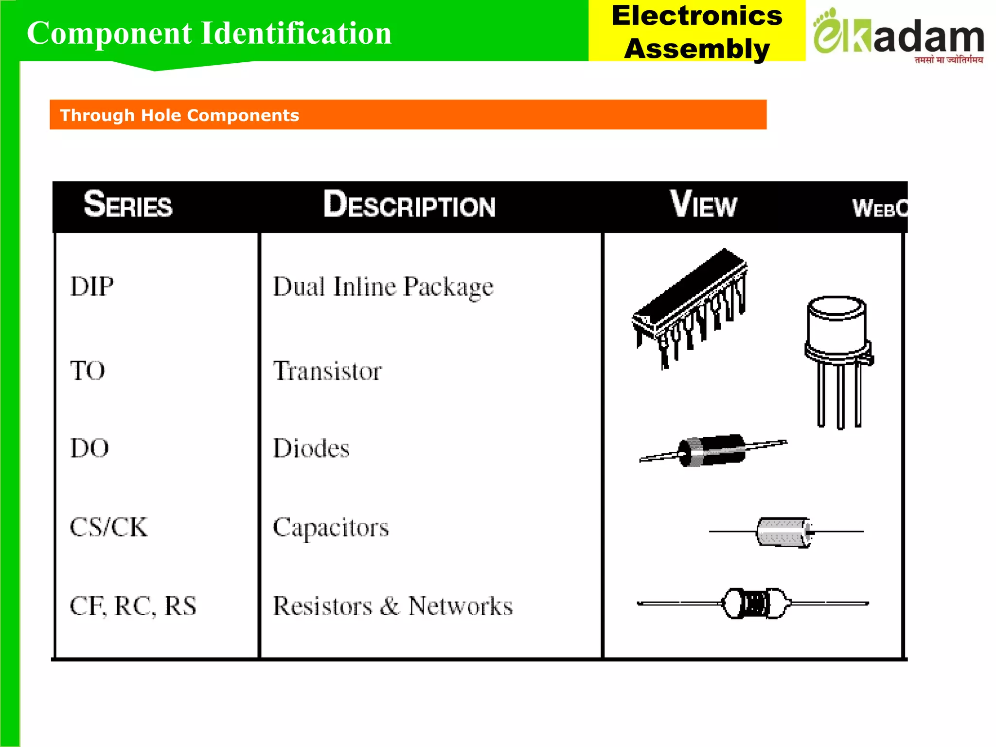
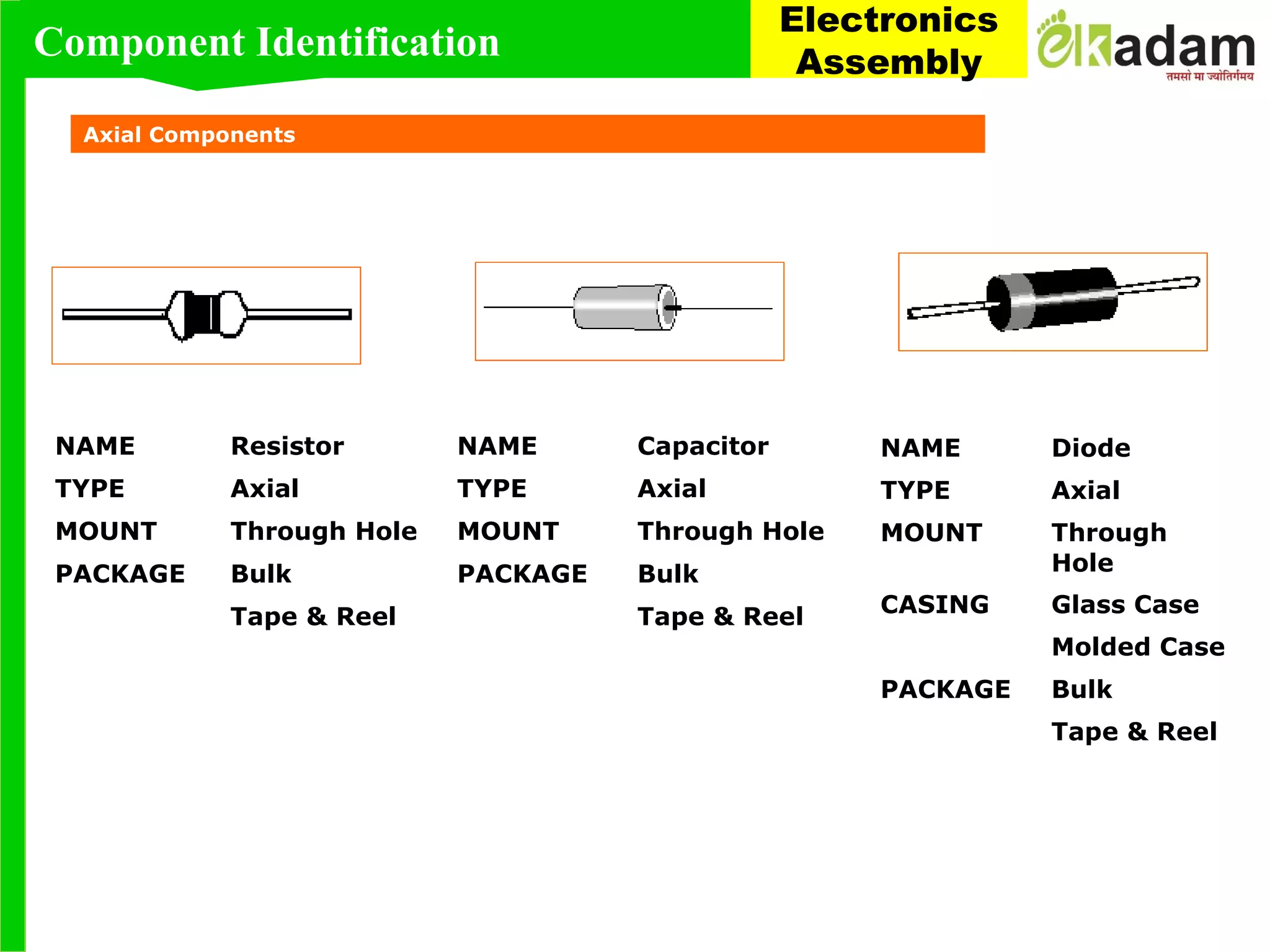
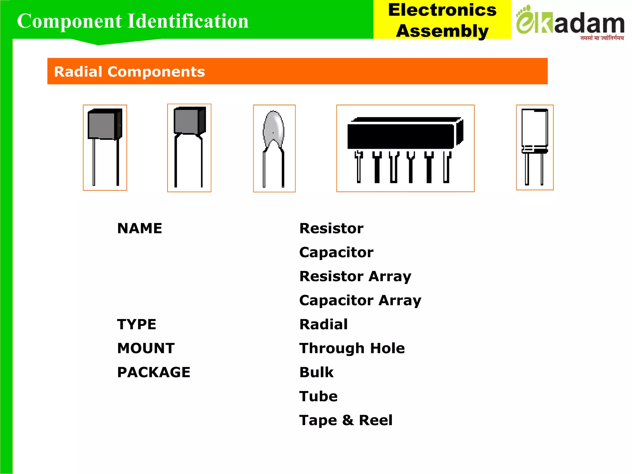
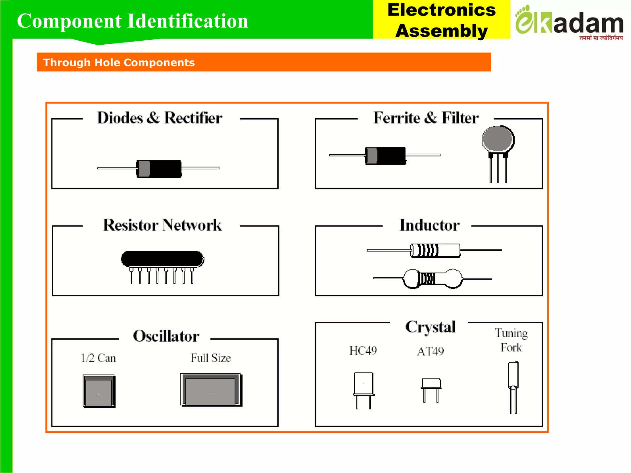
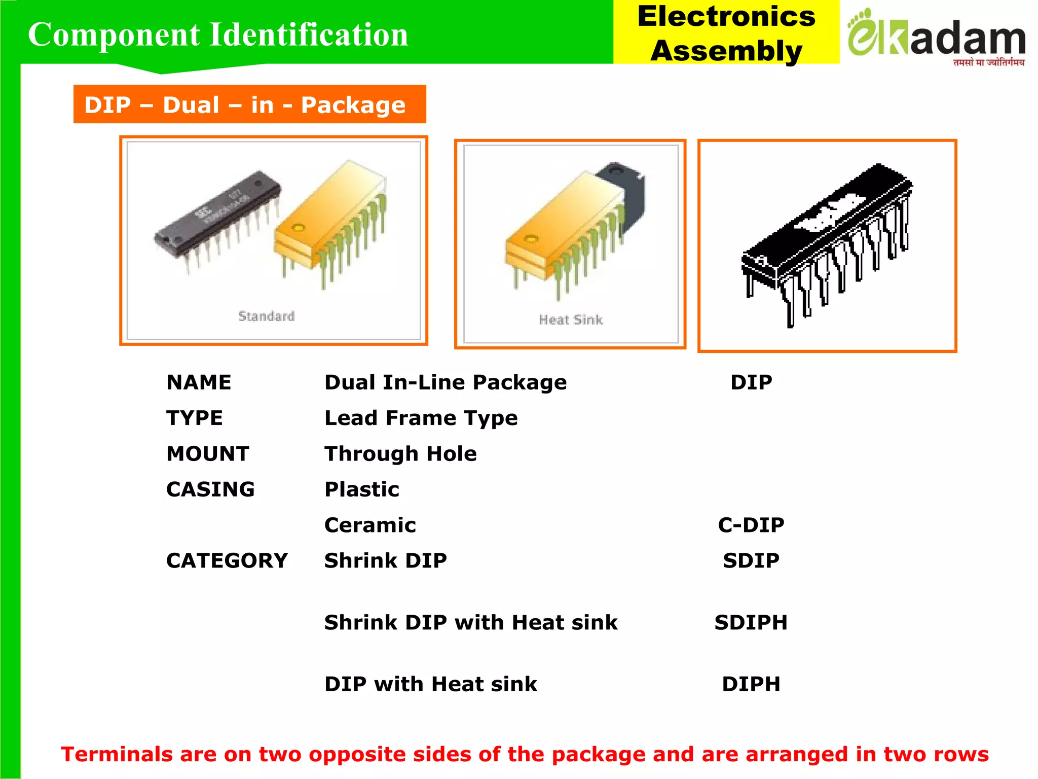
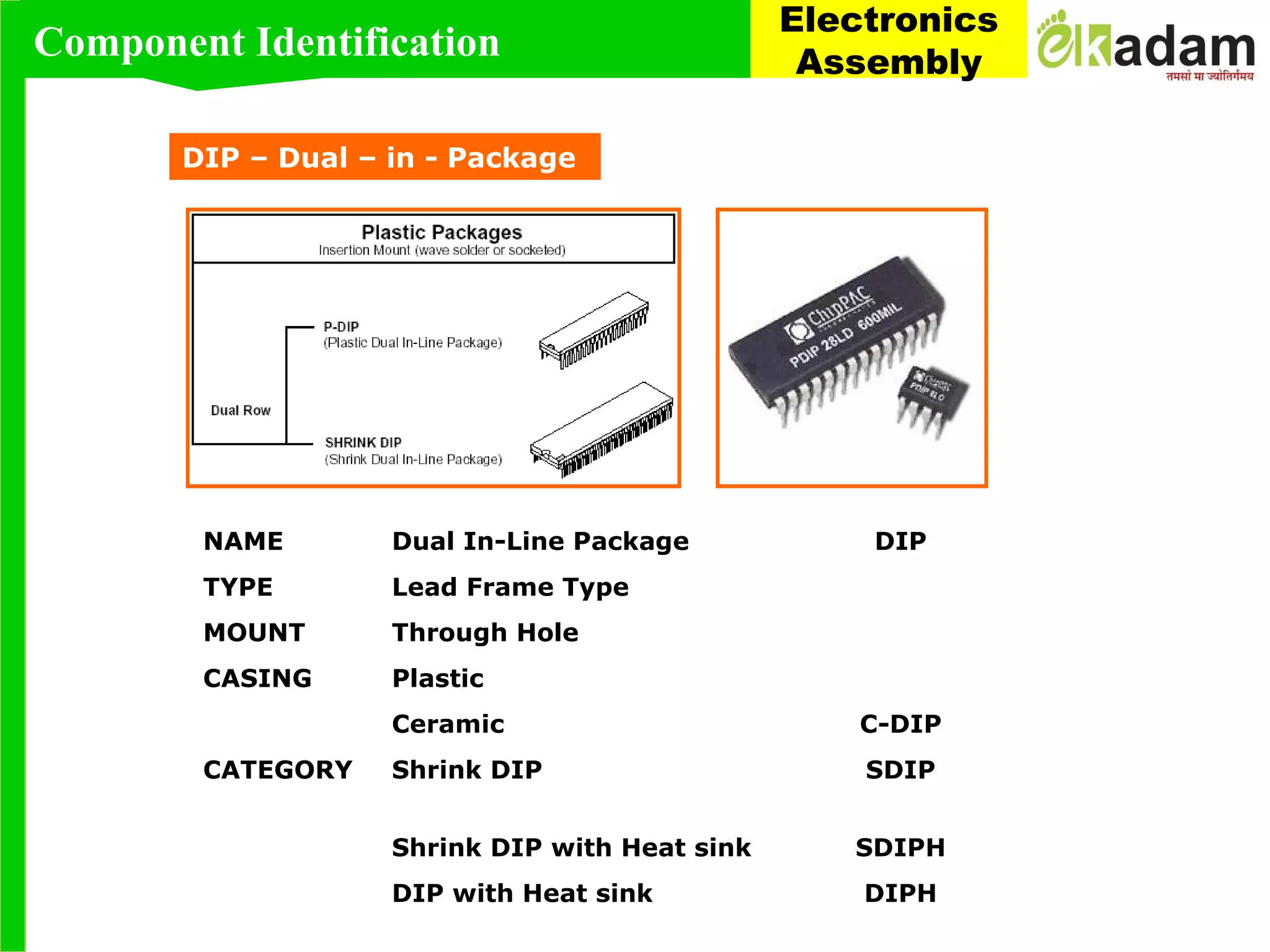
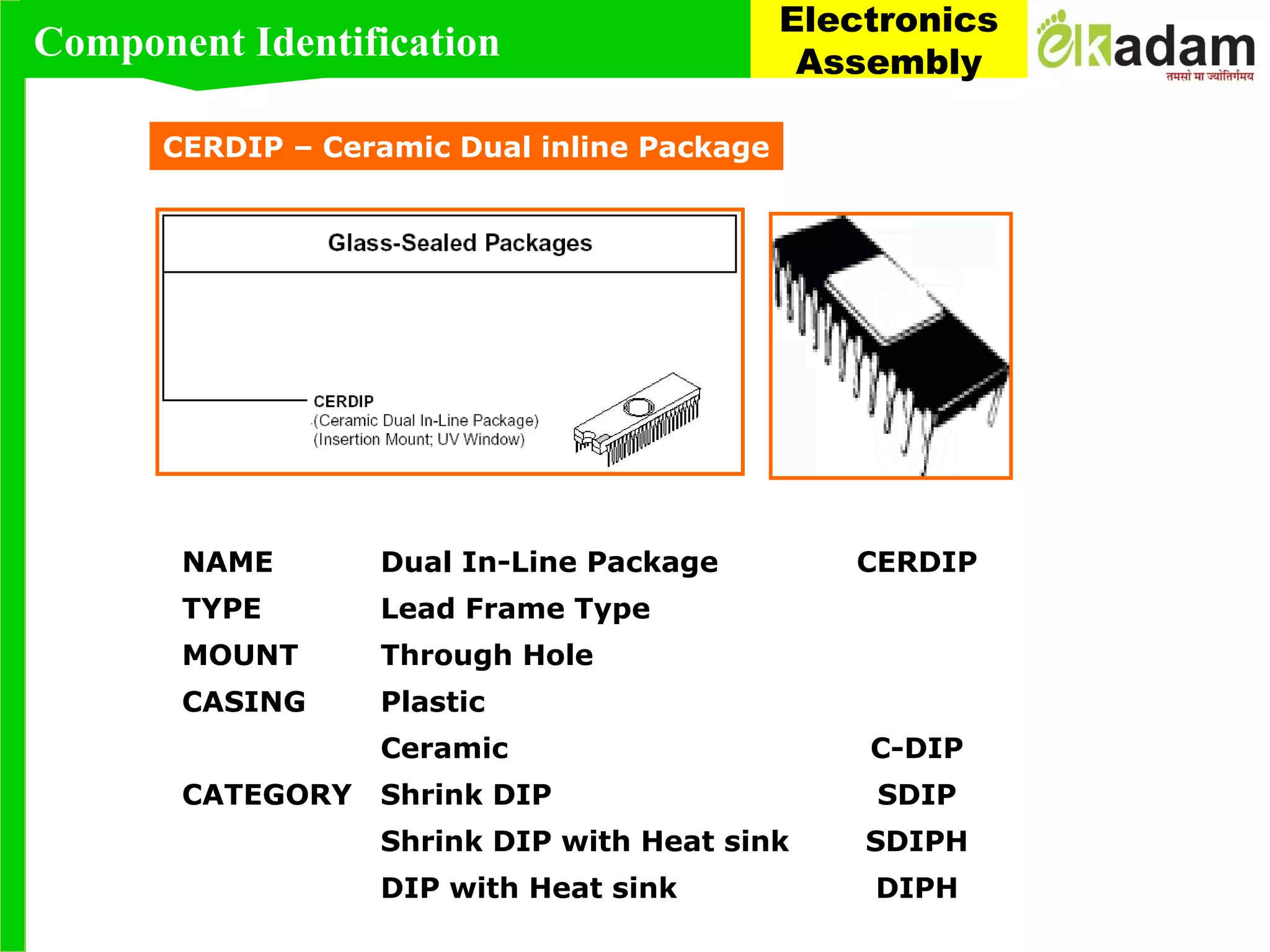
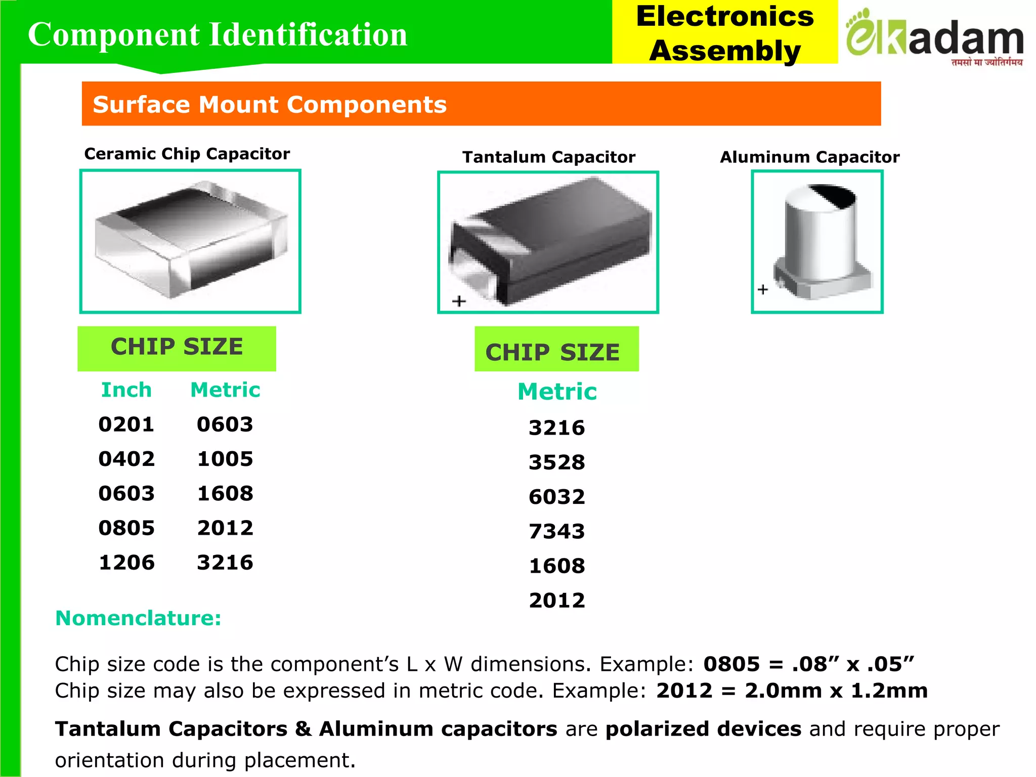
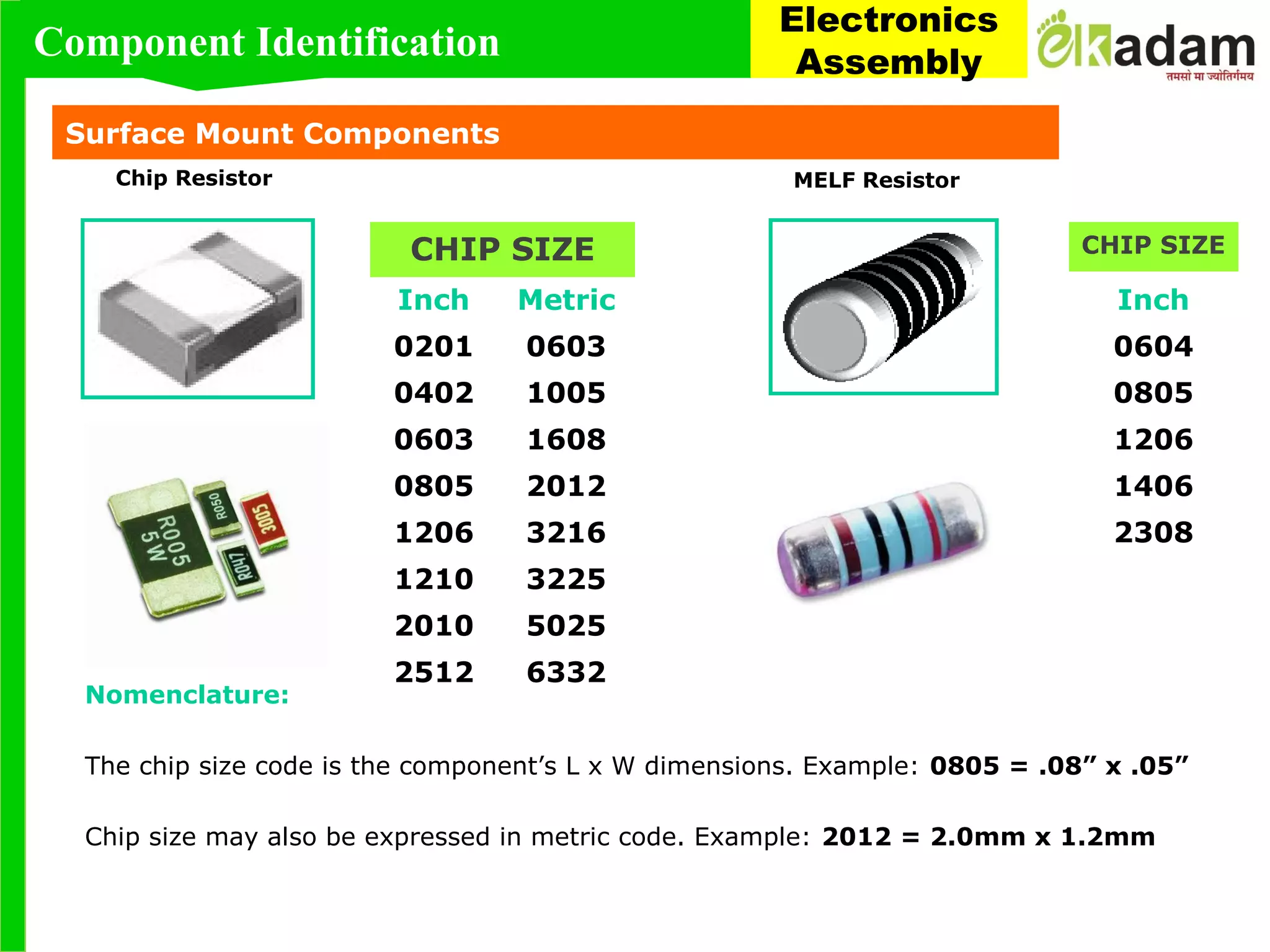
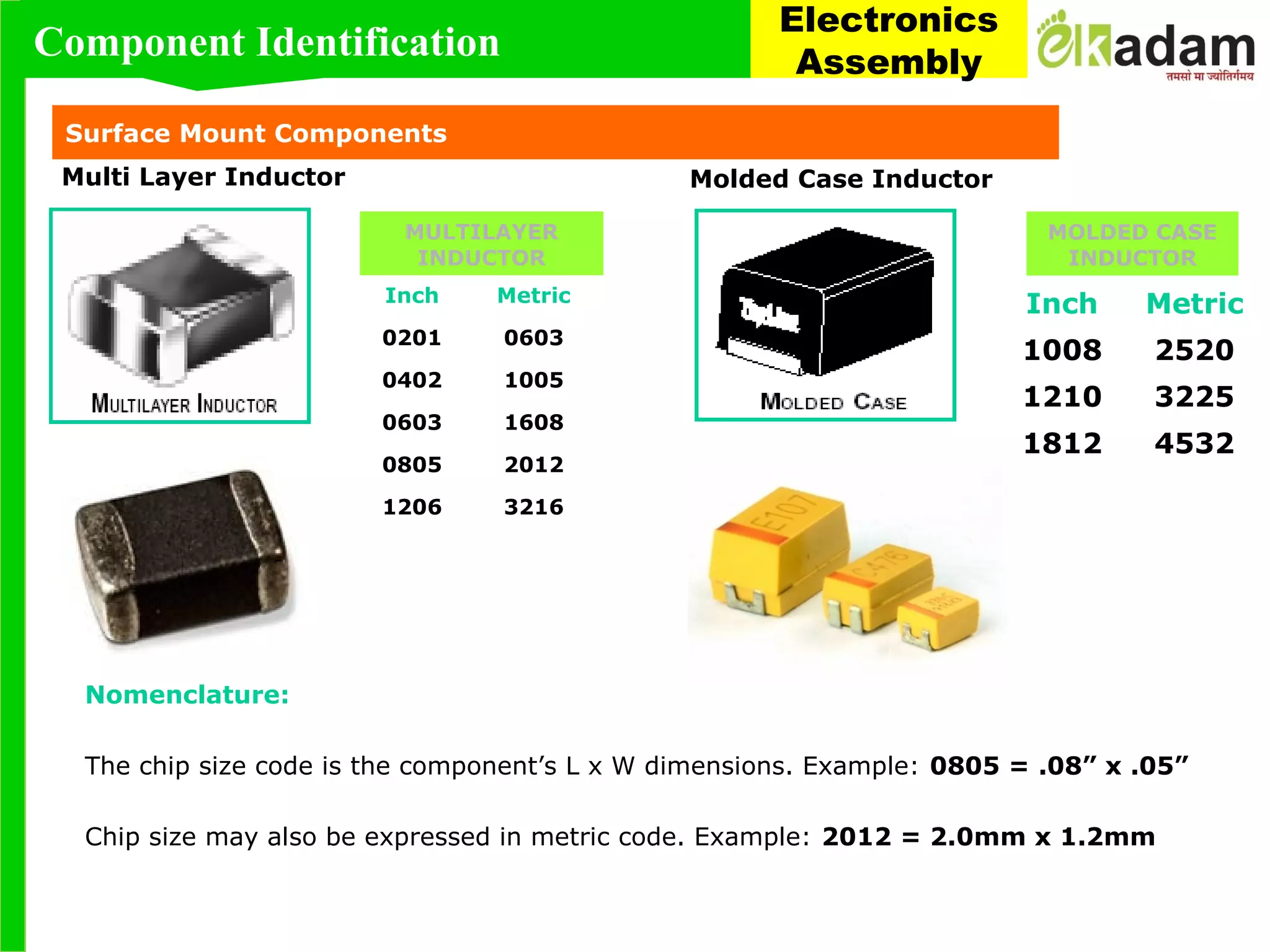
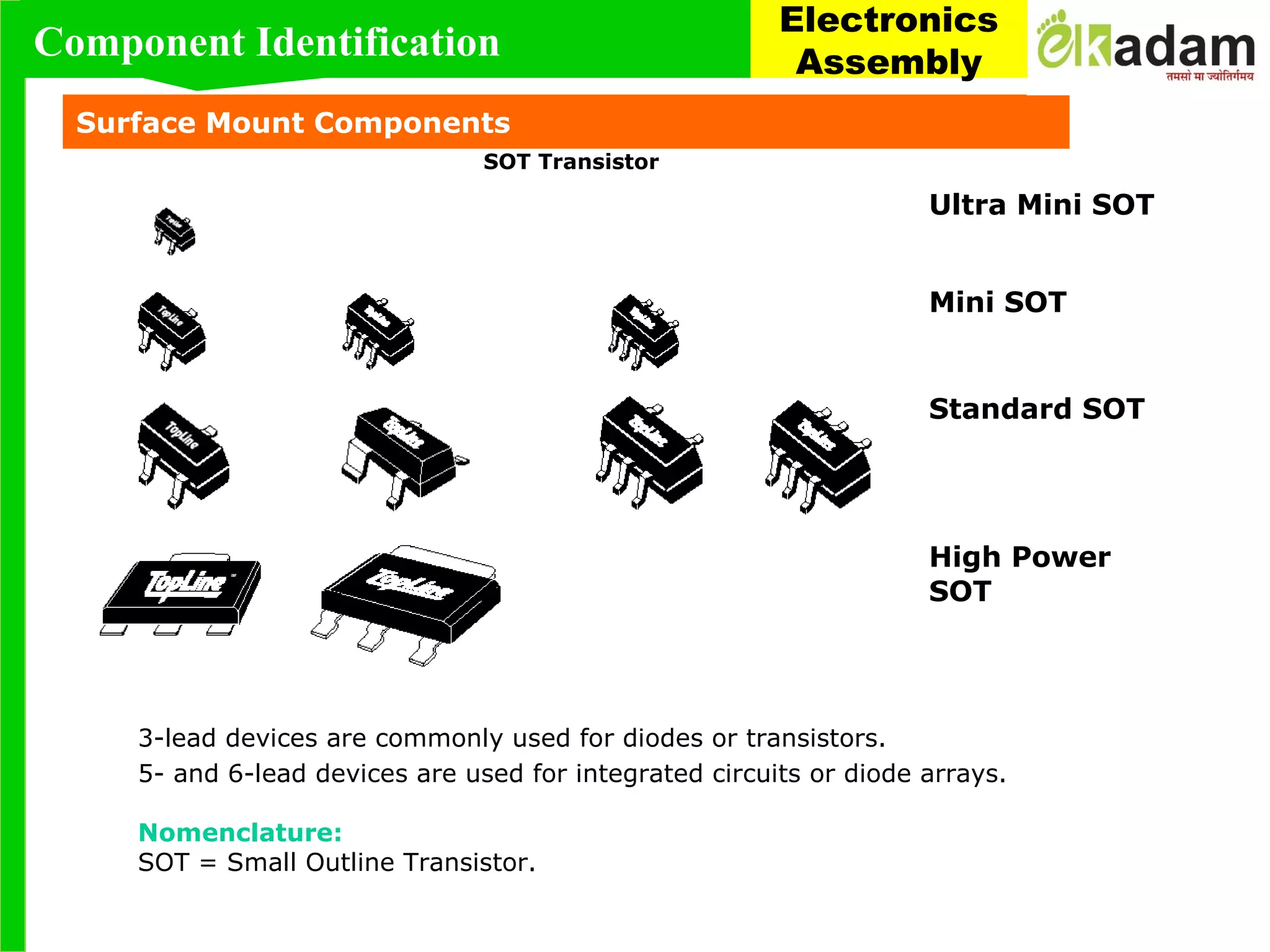
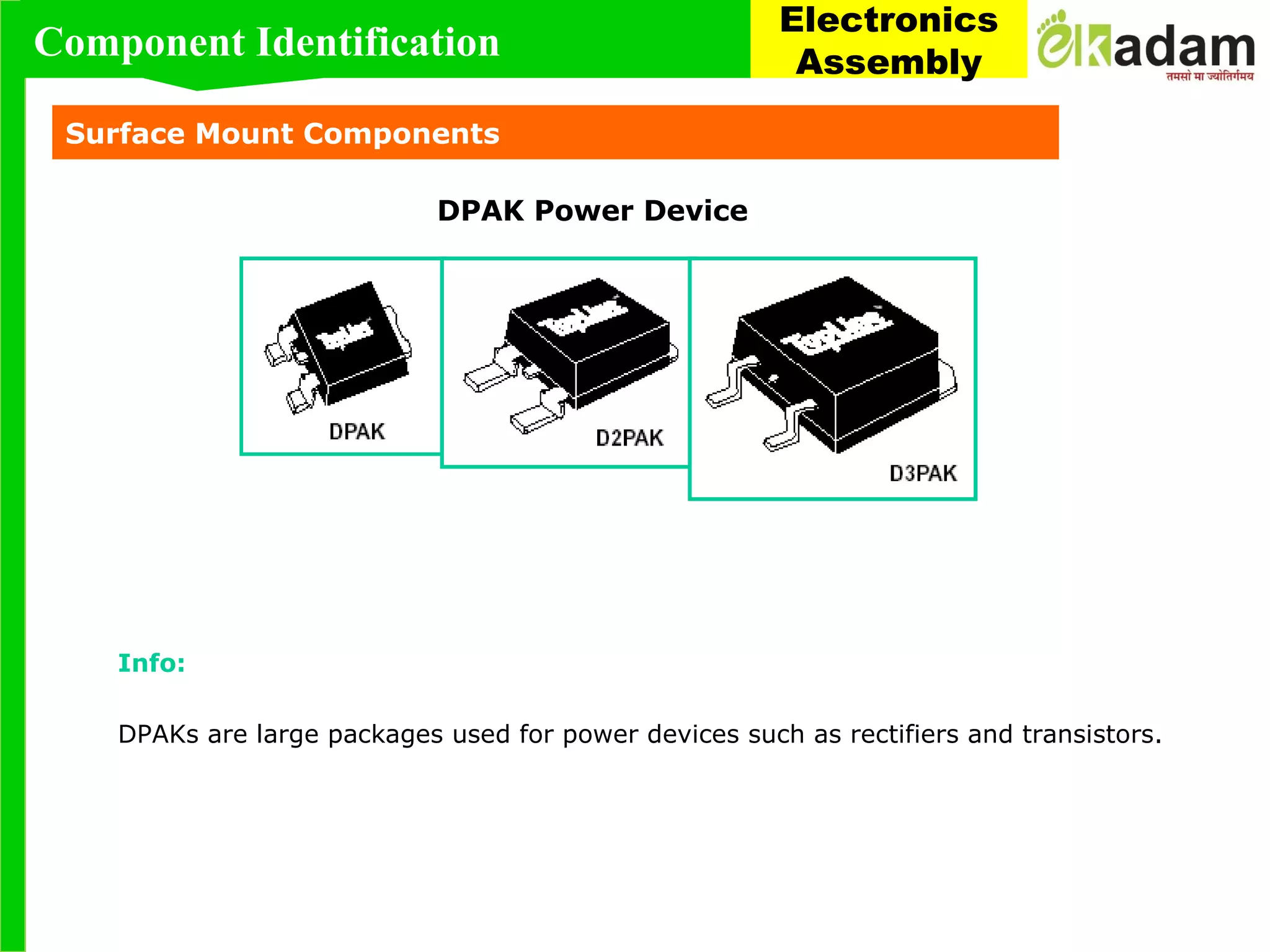
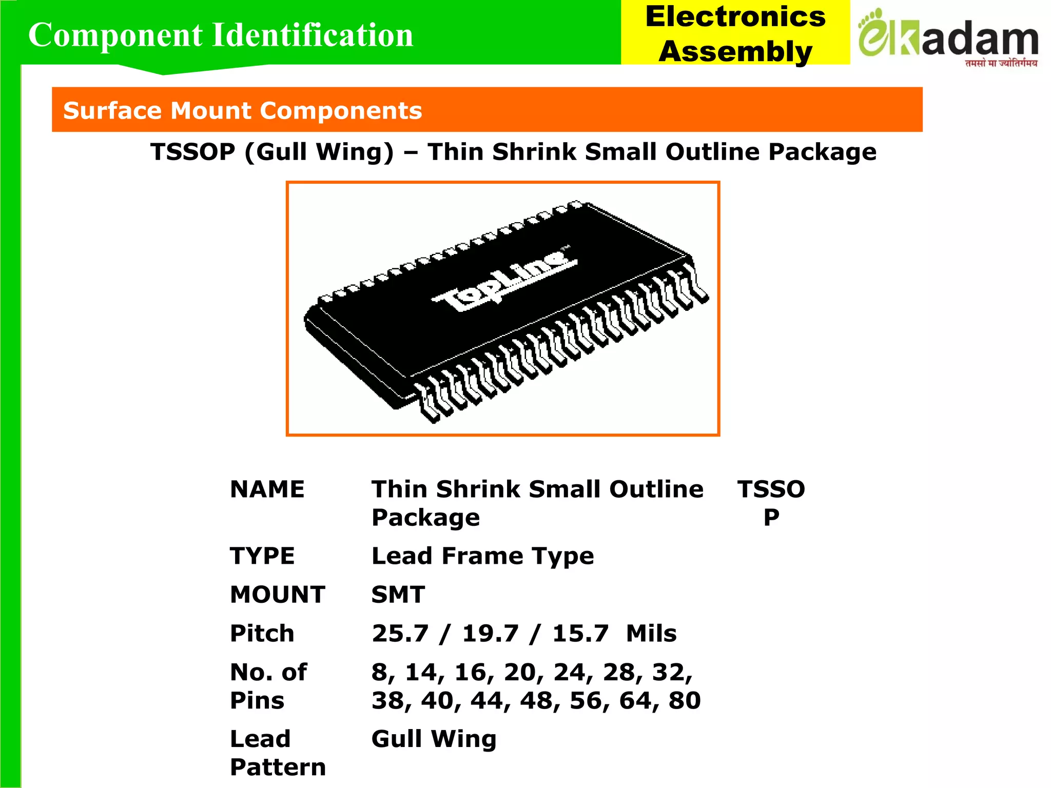
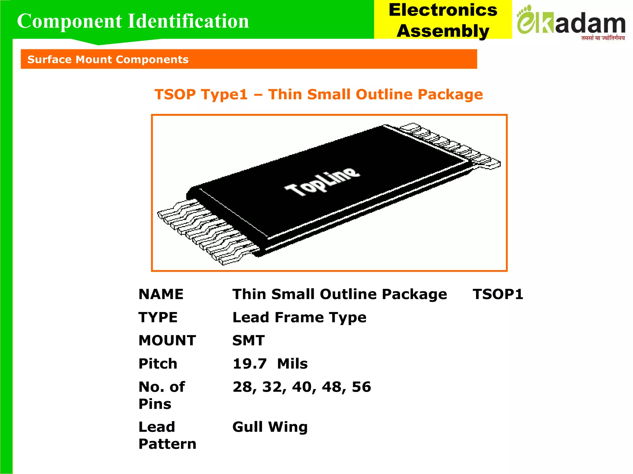
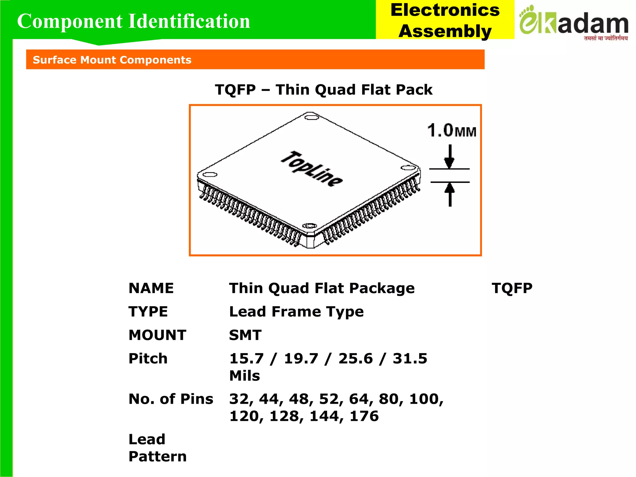
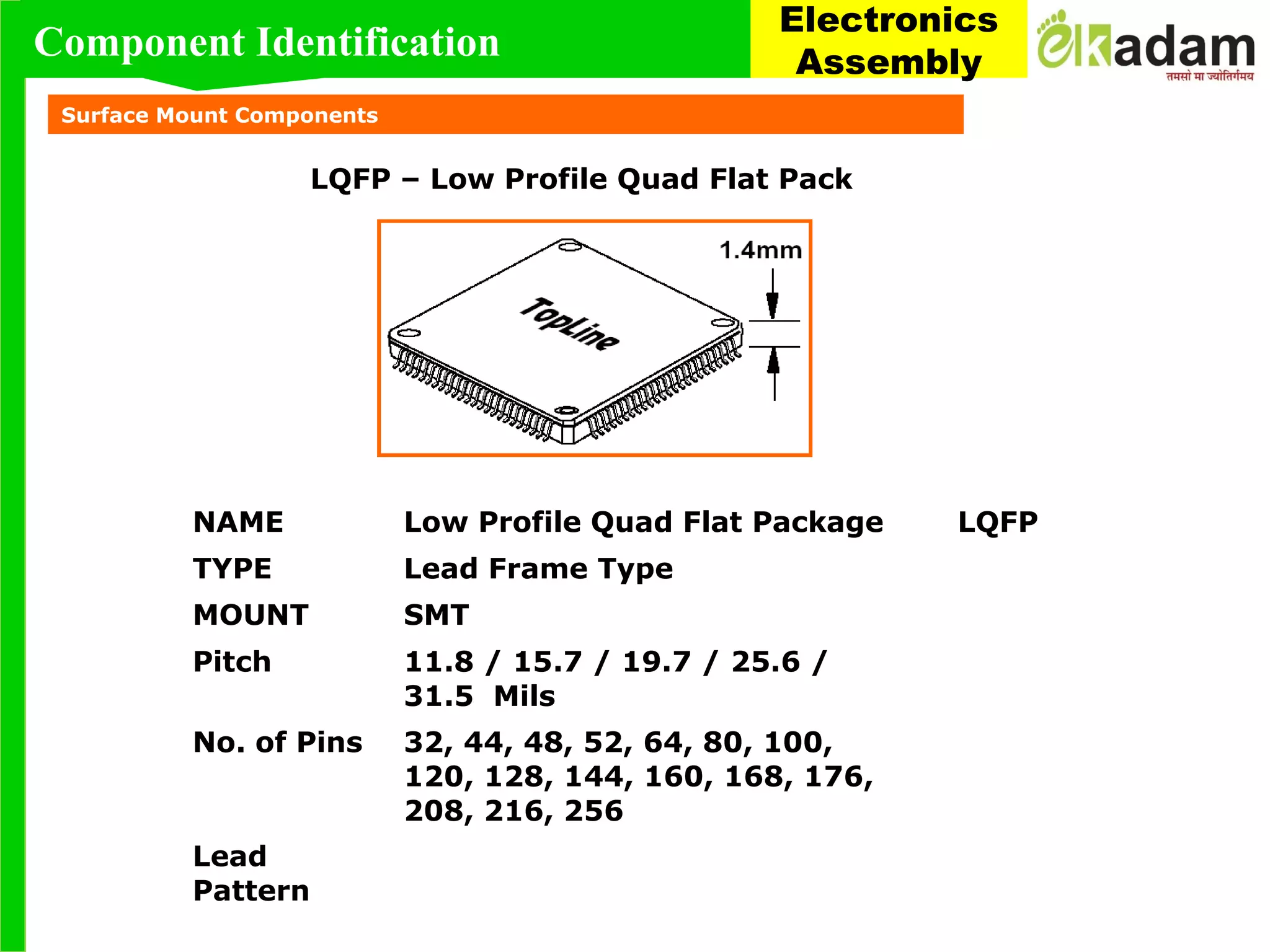
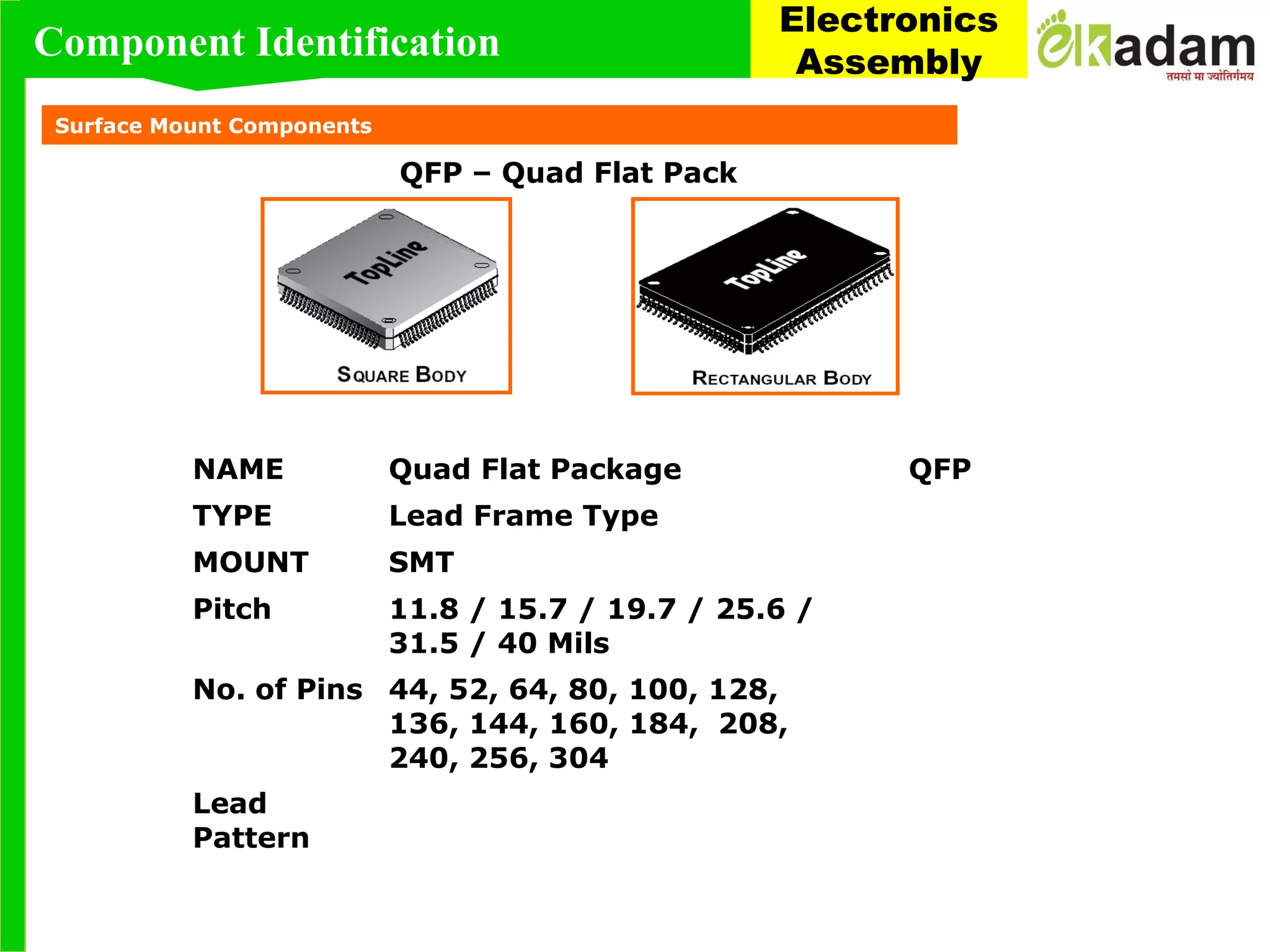
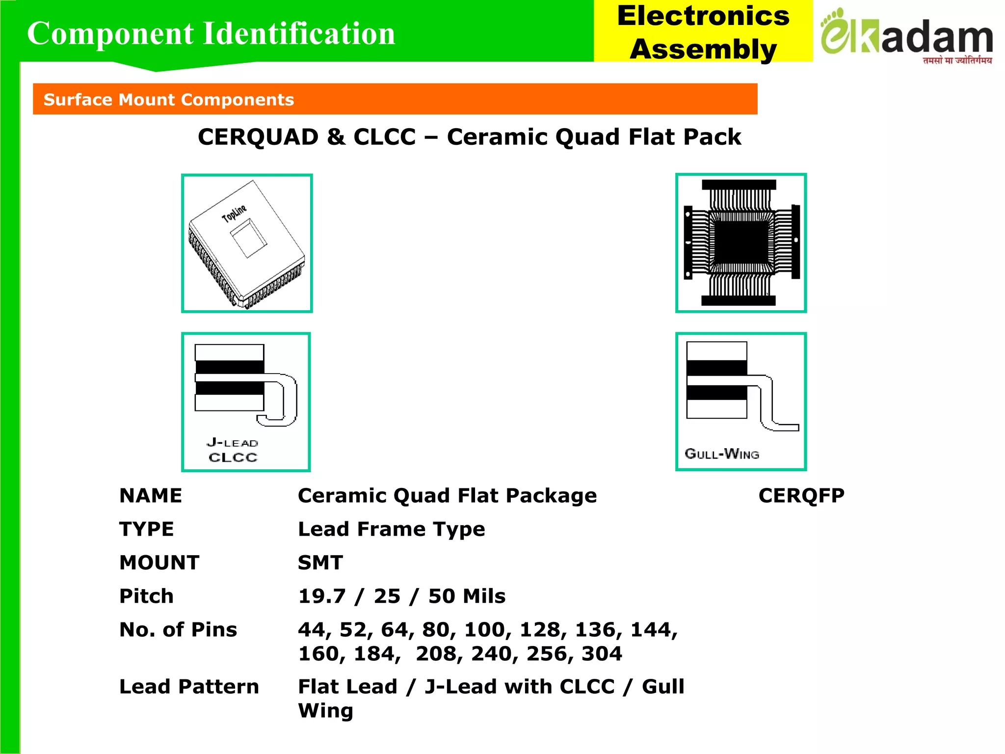
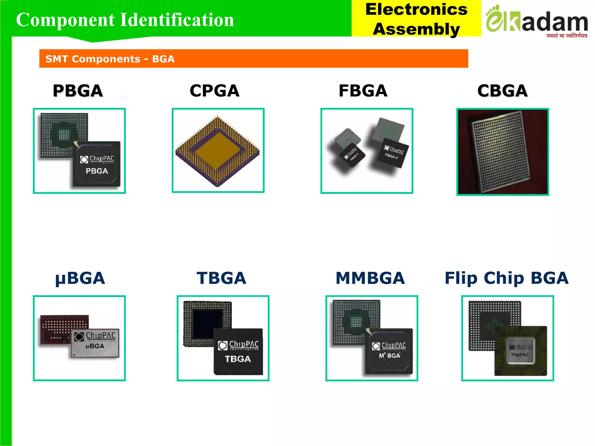
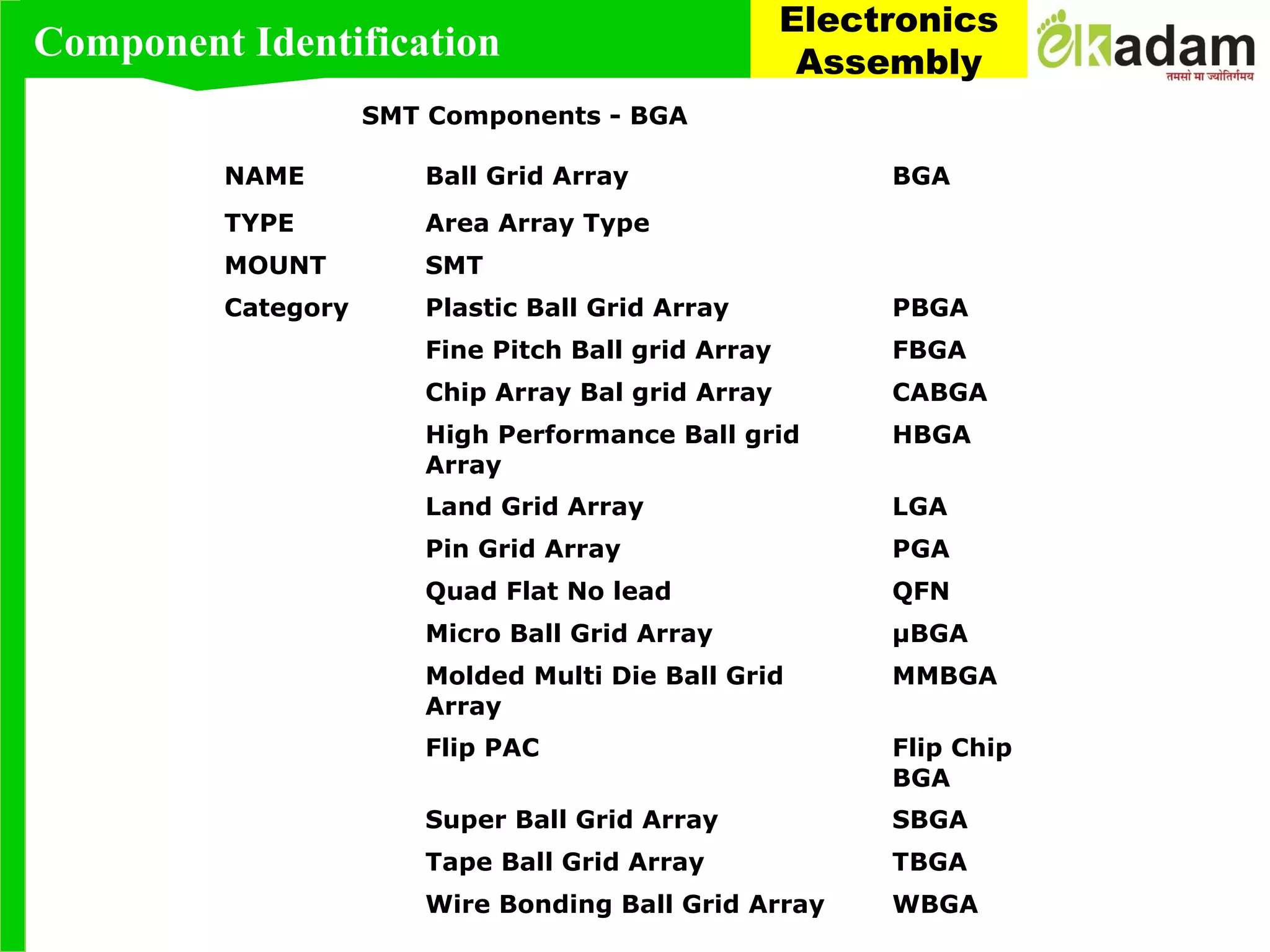
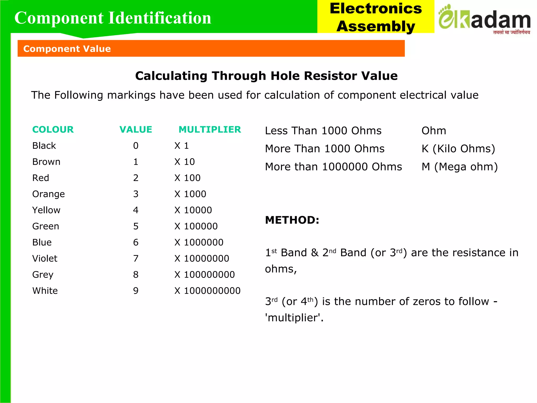
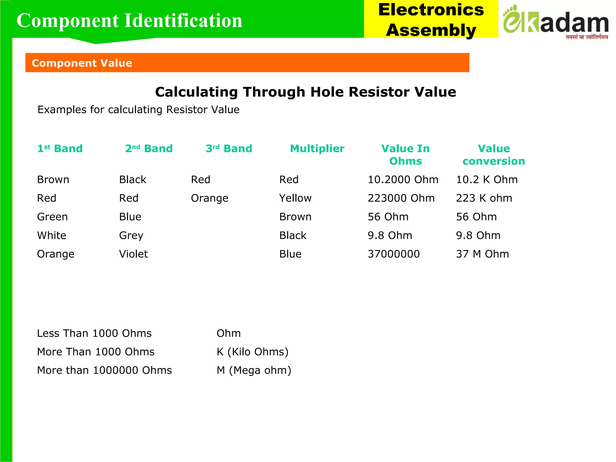
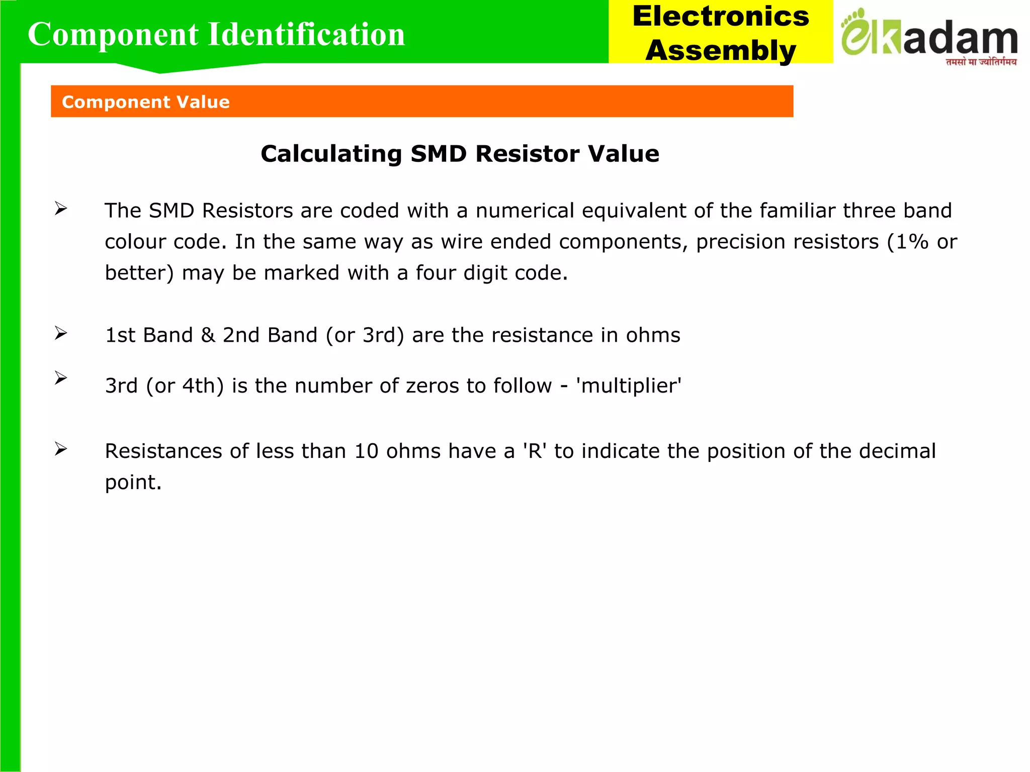
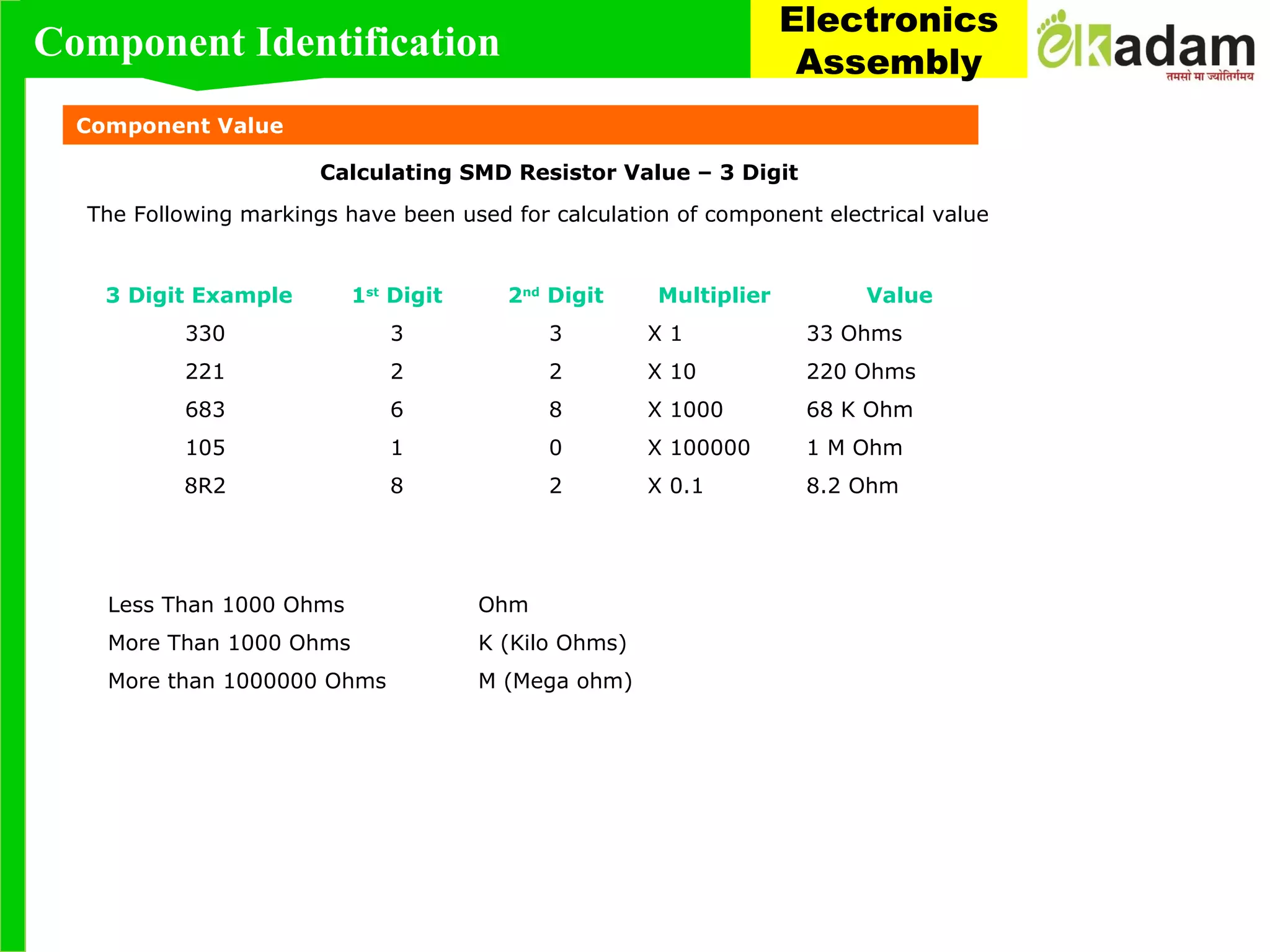
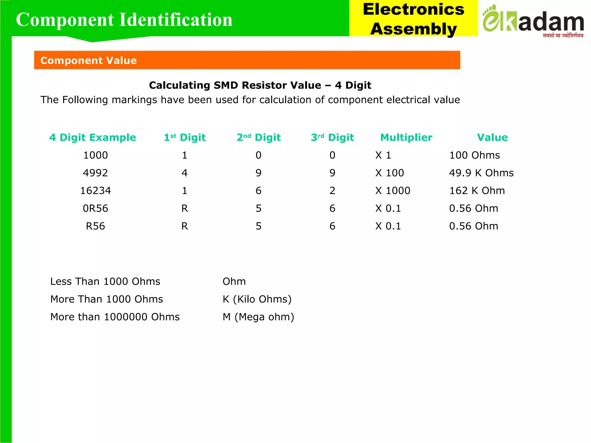
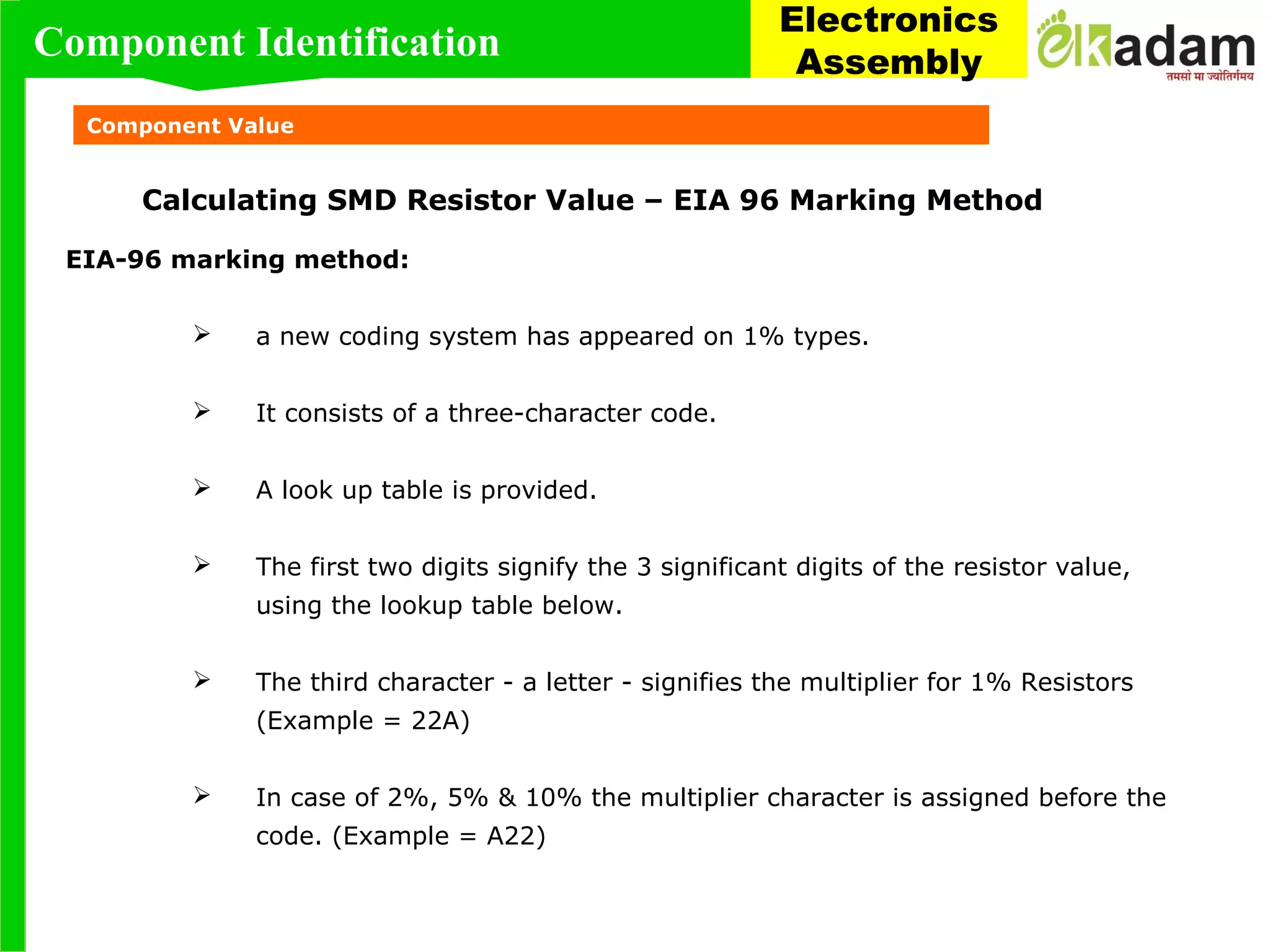
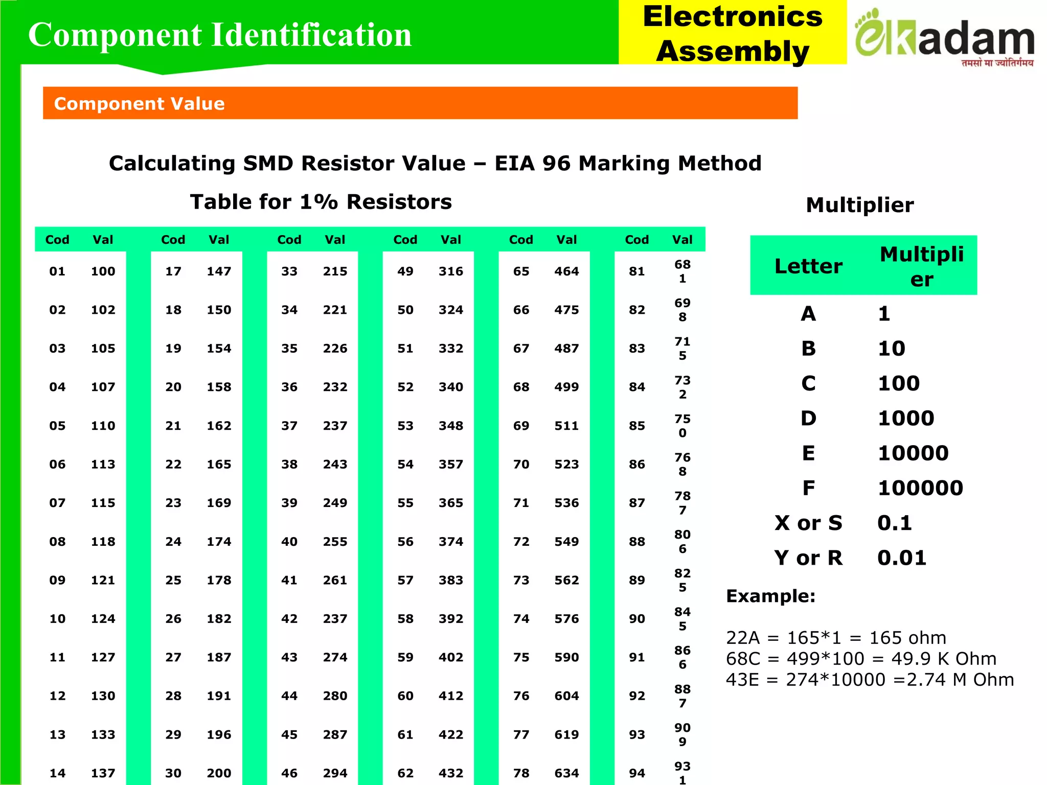
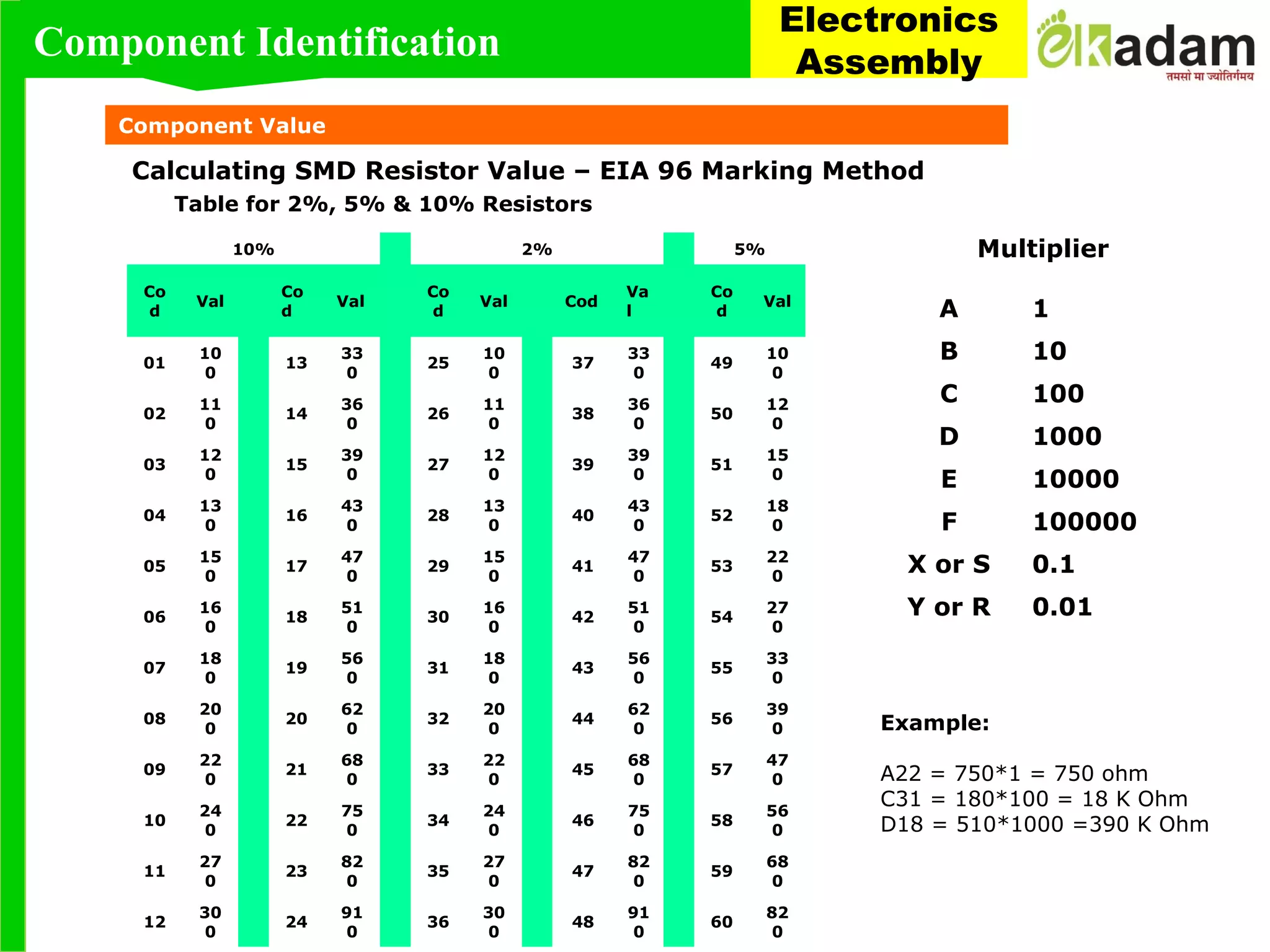
SlideShare a Scribd company logo
EK KADAM
FOUNDATION"Accelerating Youth- Accelerating Nation"
Module : Component Identification
This module covers both Through-hole and Surface mount component identification.
 The Through-hole component section will cover the identification of
 Axial Leaded Devices
 Radial Leaded Devices
 Flat packs (IC's).
 Dual in-line packages
 The surface mount component section will cover the identification of
 Chip Resistor
 Chip Capacitors
 MELF Resistors and Diodes
 Tantalum Capacitors
 SOIC
 PLCC
 QFP
 BGA
 Polarity, value, tolerance and orientation will also be discussed.
Module 1: Component Identification
Component Identification
Electronics
Assembly
Through Hole Components
Component Identification
Electronics
Assembly
Transistors
NAME Transistor
TYPE Lead Frame Type
MOUNT Through Hole
CASING Plastic
Metal
PACKAGE Bulk
Tube
Tape & Reel
Component Identification
Electronics
Assembly
Axial Components
NAME Resistor
TYPE Axial
MOUNT Through Hole
PACKAGE Bulk
Tape & Reel
NAME Capacitor
TYPE Axial
MOUNT Through Hole
PACKAGE Bulk
Tape & Reel
NAME Diode
TYPE Axial
MOUNT Through
Hole
CASING Glass Case
Molded Case
PACKAGE Bulk
Tape & Reel
Component Identification
Electronics
Assembly
NAME Resistor
Capacitor
Resistor Array
Capacitor Array
TYPE Radial
MOUNT Through Hole
PACKAGE Bulk
Tube
Tape & Reel
Radial Components
Component Identification
Electronics
Assembly
Through Hole Components
Component Identification
Electronics
Assembly
Through Hole Components
Component Identification
Electronics
Assembly
DIP – Dual – in - Package
NAME Dual In-Line Package DIP
TYPE Lead Frame Type
MOUNT Through Hole
CASING Plastic
Ceramic C-DIP
CATEGORY Shrink DIP SDIP
Shrink DIP with Heat sink SDIPH
DIP with Heat sink DIPH
Terminals are on two opposite sides of the package and are arranged in two rows
Component Identification
Electronics
Assembly
NAME Dual In-Line Package DIP
TYPE Lead Frame Type
MOUNT Through Hole
CASING Plastic
Ceramic C-DIP
CATEGORY Shrink DIP SDIP
Shrink DIP with Heat sink SDIPH
DIP with Heat sink DIPH
DIP – Dual – in - Package
Component Identification
Electronics
Assembly
NAME Dual In-Line Package CERDIP
TYPE Lead Frame Type
MOUNT Through Hole
CASING Plastic
Ceramic C-DIP
CATEGORY Shrink DIP SDIP
Shrink DIP with Heat sink SDIPH
DIP with Heat sink DIPH
CERDIP – Ceramic Dual inline Package
Component Identification
Electronics
Assembly
Inch Metric
0201 0603
0402 1005
0603 1608
0805 2012
1206 3216
Ceramic Chip Capacitor Tantalum Capacitor Aluminum Capacitor
CHIP SIZE CHIP SIZE
Metric
3216
3528
6032
7343
1608
2012
Surface Mount Components
Nomenclature:
Chip size code is the component’s L x W dimensions. Example: 0805 = .08” x .05”
Chip size may also be expressed in metric code. Example: 2012 = 2.0mm x 1.2mm
Tantalum Capacitors & Aluminum capacitors are polarized devices and require proper
orientation during placement.
Component Identification
Electronics
Assembly
Surface Mount Components
CHIP SIZE
Chip Resistor
Nomenclature:
The chip size code is the component’s L x W dimensions. Example: 0805 = .08” x .05”
Chip size may also be expressed in metric code. Example: 2012 = 2.0mm x 1.2mm
Inch Metric
0201 0603
0402 1005
0603 1608
0805 2012
1206 3216
1210 3225
2010 5025
2512 6332
Inch
0604
0805
1206
1406
2308
CHIP SIZE
MELF Resistor
Component Identification
Electronics
Assembly
Surface Mount Components
MULTILAYER
INDUCTOR
Multi Layer Inductor Molded Case Inductor
Nomenclature:
The chip size code is the component’s L x W dimensions. Example: 0805 = .08” x .05”
Chip size may also be expressed in metric code. Example: 2012 = 2.0mm x 1.2mm
Inch Metric
0201 0603
0402 1005
0603 1608
0805 2012
1206 3216
Inch Metric
1008 2520
1210 3225
1812 4532
MOLDED CASE
INDUCTOR
Component Identification
Electronics
Assembly
Ultra Mini SOT
Mini SOT
Standard SOT
High Power
SOT
Surface Mount Components
SOT Transistor
3-lead devices are commonly used for diodes or transistors.
5- and 6-lead devices are used for integrated circuits or diode arrays.
Nomenclature:
SOT = Small Outline Transistor.
Component Identification
Electronics
Assembly
Info:
DPAKs are large packages used for power devices such as rectifiers and transistors.
Surface Mount Components
DPAK Power Device
Component Identification
Electronics
Assembly
 MELF and Mini MELF diodes are cylindrical cases constructed of glass or plastic.
 The glass package is commonly used lower power diodes.
 The Plastic package is used for high current rectifiers and zener diodes.
Nomenclature:
DO = Diode Outline
Surface Mount Components
MELF Diodes
Component Identification
Electronics
Assembly
Surface Mount Components
C-Bend Lead Gull Wing Lead
Rectangular Diodes
 Rectangular diodes and rectifiers are available in Gull-wing and C-bend leads (J-
leads).
 C-bend leads are similar to J-leads.
Nomenclature:
DO = Diode Outline
SOD = Small outline Diode
Component Identification
Electronics
Assembly
NAME Plastic Leaded Chip Carrier PLCC
TYPE Lead Frame Type
MOUNT SMT
CASING Plastic
Pitch 50 Mils
No. of Pins 18, 20, 28, 32, 44, 52, 68, 84
PACKAGE TUBE
Tape & Reel
Surface Mount Components
Plastic Leaded Chip Carrier
Component Identification
Electronics
Assembly
NAME Leadless Chip Carrier LCC
MOUNT SMT / Socket Mount
Pitch 50 Mils
No. of
Pins
20, 28, 32, 44, 52, 68, 84
Surface Mount Components
Leadless Chip Carrier
Component Identification
Electronics
Assembly
Surface Mount Components
SOIC – Small Outline Gull Wing
NAME Small Outline Gull wing SOIC
TYPE Lead Frame Type
MOUNT SMT
Pitch 50 Mils
No. of
Pins
4, 8, 14, 16, 18, 20, 28,
32, 40, 44
PACKAGE TUBE
Tape & Reel
Component Identification
Electronics
Assembly
Surface Mount Components
SOJ – Small Outline J-Lead
NAME Small Outline J-Lead SOJ
TYPE Lead Frame Type
MOUNT SMT
Pitch 50 Mils
No. of Pins 18, 20, 28, 32, 40, 42, 44
PACKAGE TUBE
Tape & Reel
Lead
Pattern
J - Lead
Component Identification
Electronics
Assembly
Surface Mount Components
MSOP (Gull Wing) – Miniature Small Outline Package
NAME Miniature Small
Outline Package
MSOP
TYPE Lead Frame Type
MOUNT SMT
Pitch 25.6 / 19.7 Mils
No. of
Pins
8, 10
Lead
Pattern
Gull Wing
Component Identification
Electronics
Assembly
Surface Mount Components
SSOP (Gull Wing) – Shrink Small Outline Package
NAME Shrink Small Outline
Package
SSOP
TYPE Lead Frame Type
MOUNT SMT
Pitch 25.7 / 31.5 Mils
No. of
Pins
8, 14, 16, 20, 24, 28,
34, 36, 40, 44, 48, 56,
64, 80
Lead
Pattern
Gull Wing
Component Identification
Electronics
Assembly
Surface Mount Components
TSSOP (Gull Wing) – Thin Shrink Small Outline Package
NAME Thin Shrink Small Outline
Package
TSSO
P
TYPE Lead Frame Type
MOUNT SMT
Pitch 25.7 / 19.7 / 15.7 Mils
No. of
Pins
8, 14, 16, 20, 24, 28, 32,
38, 40, 44, 48, 56, 64, 80
Lead
Pattern
Gull Wing
Component Identification
Electronics
Assembly
Surface Mount Components
TSOP Type1 – Thin Small Outline Package
NAME Thin Small Outline Package TSOP1
TYPE Lead Frame Type
MOUNT SMT
Pitch 19.7 Mils
No. of
Pins
28, 32, 40, 48, 56
Lead
Pattern
Gull Wing
Component Identification
Electronics
Assembly
Surface Mount Components
TQFP – Thin Quad Flat Pack
NAME Thin Quad Flat Package TQFP
TYPE Lead Frame Type
MOUNT SMT
Pitch 15.7 / 19.7 / 25.6 / 31.5
Mils
No. of Pins 32, 44, 48, 52, 64, 80, 100,
120, 128, 144, 176
Lead
Pattern
Component Identification
Electronics
Assembly
Surface Mount Components
LQFP – Low Profile Quad Flat Pack
NAME Low Profile Quad Flat Package LQFP
TYPE Lead Frame Type
MOUNT SMT
Pitch 11.8 / 15.7 / 19.7 / 25.6 /
31.5 Mils
No. of Pins 32, 44, 48, 52, 64, 80, 100,
120, 128, 144, 160, 168, 176,
208, 216, 256
Lead
Pattern
Component Identification
Electronics
Assembly
Surface Mount Components
QFP – Quad Flat Pack
NAME Quad Flat Package QFP
TYPE Lead Frame Type
MOUNT SMT
Pitch 11.8 / 15.7 / 19.7 / 25.6 /
31.5 / 40 Mils
No. of Pins 44, 52, 64, 80, 100, 128,
136, 144, 160, 184, 208,
240, 256, 304
Lead
Pattern
Component Identification
Electronics
Assembly
Surface Mount Components
CERQUAD & CLCC – Ceramic Quad Flat Pack
NAME Ceramic Quad Flat Package CERQFP
TYPE Lead Frame Type
MOUNT SMT
Pitch 19.7 / 25 / 50 Mils
No. of Pins 44, 52, 64, 80, 100, 128, 136, 144,
160, 184, 208, 240, 256, 304
Lead Pattern Flat Lead / J-Lead with CLCC / Gull
Wing
Component Identification
Electronics
Assembly
SMT Components - BGA
CPGA CBGACBGAFBGA
µBGA
PBGAPBGA
TBGA MMBGA Flip Chip BGA
Component Identification
Electronics
Assembly
SMT Components - BGA
NAME Ball Grid Array BGA
TYPE Area Array Type
MOUNT SMT
Category Plastic Ball Grid Array PBGA
Fine Pitch Ball grid Array FBGA
Chip Array Bal grid Array CABGA
High Performance Ball grid
Array
HBGA
Land Grid Array LGA
Pin Grid Array PGA
Quad Flat No lead QFN
Micro Ball Grid Array µBGA
Molded Multi Die Ball Grid
Array
MMBGA
Flip PAC Flip Chip
BGA
Super Ball Grid Array SBGA
Tape Ball Grid Array TBGA
Wire Bonding Ball Grid Array WBGA
Component Identification
Electronics
Assembly
COLOUR VALUE MULTIPLIER
Black 0 X 1
Brown 1 X 10
Red 2 X 100
Orange 3 X 1000
Yellow 4 X 10000
Green 5 X 100000
Blue 6 X 1000000
Violet 7 X 10000000
Grey 8 X 100000000
White 9 X 1000000000
Less Than 1000 Ohms Ohm
More Than 1000 Ohms K (Kilo Ohms)
More than 1000000 Ohms M (Mega ohm)
Calculating Through Hole Resistor Value
The Following markings have been used for calculation of component electrical value
METHOD:
1st
Band & 2nd
Band (or 3rd
) are the resistance in
ohms,
3rd
(or 4th
) is the number of zeros to follow -
'multiplier'.
Component Identification
Electronics
Assembly
Component Value
Component Value
1st
Band 2nd
Band 3rd
Band Multiplier Value In
Ohms
Value
conversion
Brown Black Red Red 10.2000 Ohm 10.2 K Ohm
Red Red Orange Yellow 223000 Ohm 223 K ohm
Green Blue Brown 56 Ohm 56 Ohm
White Grey Black 9.8 Ohm 9.8 Ohm
Orange Violet Blue 37000000 37 M Ohm
Examples for calculating Resistor Value
Less Than 1000 Ohms Ohm
More Than 1000 Ohms K (Kilo Ohms)
More than 1000000 Ohms M (Mega ohm)
Calculating Through Hole Resistor Value
Component Identification
Electronics
Assembly
Component Value
Calculating SMD Resistor Value
 The SMD Resistors are coded with a numerical equivalent of the familiar three band
colour code. In the same way as wire ended components, precision resistors (1% or
better) may be marked with a four digit code.
 1st Band & 2nd Band (or 3rd) are the resistance in ohms
 3rd (or 4th) is the number of zeros to follow - 'multiplier'
 Resistances of less than 10 ohms have a 'R' to indicate the position of the decimal
point.
Component Identification
Electronics
Assembly
Component Value
3 Digit Example 1st
Digit 2nd
Digit Multiplier Value
330 3 3 X 1 33 Ohms
221 2 2 X 10 220 Ohms
683 6 8 X 1000 68 K Ohm
105 1 0 X 100000 1 M Ohm
8R2 8 2 X 0.1 8.2 Ohm
Less Than 1000 Ohms Ohm
More Than 1000 Ohms K (Kilo Ohms)
More than 1000000 Ohms M (Mega ohm)
The Following markings have been used for calculation of component electrical value
Calculating SMD Resistor Value – 3 Digit
Component Identification
Electronics
Assembly
Component Value
4 Digit Example 1st
Digit 2nd
Digit 3rd
Digit Multiplier Value
1000 1 0 0 X 1 100 Ohms
4992 4 9 9 X 100 49.9 K Ohms
16234 1 6 2 X 1000 162 K Ohm
0R56 R 5 6 X 0.1 0.56 Ohm
R56 R 5 6 X 0.1 0.56 Ohm
Less Than 1000 Ohms Ohm
More Than 1000 Ohms K (Kilo Ohms)
More than 1000000 Ohms M (Mega ohm)
The Following markings have been used for calculation of component electrical value
Calculating SMD Resistor Value – 4 Digit
Component Identification
Electronics
Assembly
Component Value
Calculating SMD Resistor Value – EIA 96 Marking Method
EIA-96 marking method:
 a new coding system has appeared on 1% types.
 It consists of a three-character code.
 A look up table is provided.
 The first two digits signify the 3 significant digits of the resistor value,
using the lookup table below.
 The third character - a letter - signifies the multiplier for 1% Resistors
(Example = 22A)
 In case of 2%, 5% & 10% the multiplier character is assigned before the
code. (Example = A22)
Component Identification
Electronics
Assembly
Component Value
Calculating SMD Resistor Value – EIA 96 Marking Method
Letter
Multipli
er
A 1
B 10
C 100
D 1000
E 10000
F 100000
X or S 0.1
Y or R 0.01
Table for 1% Resistors Multiplier
Example:
22A = 165*1 = 165 ohm
68C = 499*100 = 49.9 K Ohm
43E = 274*10000 =2.74 M Ohm
Cod Val Cod Val Cod Val Cod Val Cod Val Cod Val
01 100 17 147 33 215 49 316 65 464 81
68
1
02 102 18 150 34 221 50 324 66 475 82
69
8
03 105 19 154 35 226 51 332 67 487 83
71
5
04 107 20 158 36 232 52 340 68 499 84
73
2
05 110 21 162 37 237 53 348 69 511 85
75
0
06 113 22 165 38 243 54 357 70 523 86
76
8
07 115 23 169 39 249 55 365 71 536 87
78
7
08 118 24 174 40 255 56 374 72 549 88
80
6
09 121 25 178 41 261 57 383 73 562 89
82
5
10 124 26 182 42 237 58 392 74 576 90
84
5
11 127 27 187 43 274 59 402 75 590 91
86
6
12 130 28 191 44 280 60 412 76 604 92
88
7
13 133 29 196 45 287 61 422 77 619 93
90
9
14 137 30 200 46 294 62 432 78 634 94
93
1
Component Identification
Electronics
Assembly
Component Value
Calculating SMD Resistor Value – EIA 96 Marking Method
Table for 2%, 5% & 10% Resistors
Multiplier
Example:
A22 = 750*1 = 750 ohm
C31 = 180*100 = 18 K Ohm
D18 = 510*1000 =390 K Ohm
10% 2% 5%
Co
d
Val
Co
d
Val
Co
d
Val Cod
Va
l
Co
d
Val
01
10
0
13
33
0
25
10
0
37
33
0
49
10
0
02
11
0
14
36
0
26
11
0
38
36
0
50
12
0
03
12
0
15
39
0
27
12
0
39
39
0
51
15
0
04
13
0
16
43
0
28
13
0
40
43
0
52
18
0
05
15
0
17
47
0
29
15
0
41
47
0
53
22
0
06
16
0
18
51
0
30
16
0
42
51
0
54
27
0
07
18
0
19
56
0
31
18
0
43
56
0
55
33
0
08
20
0
20
62
0
32
20
0
44
62
0
56
39
0
09
22
0
21
68
0
33
22
0
45
68
0
57
47
0
10
24
0
22
75
0
34
24
0
46
75
0
58
56
0
11
27
0
23
82
0
35
27
0
47
82
0
59
68
0
12
30
0
24
91
0
36
30
0
48
91
0
60
82
0
A 1
B 10
C 100
D 1000
E 10000
F 100000
X or S 0.1
Y or R 0.01
Component Identification
Electronics
Assembly
Component Value
Calculating SMD Capacitor Value – EIA 96 Marking Method
EIA-96 marking method:
 SMD ceramic capacitors are sometimes marked with a code, consisting of
one or two letters and a digit.
 The first letter if present is a manufacturer code (i.e K for Kemet, etc.)
 The second letter the mantissa and the digit the exponent (multiplier) of
the capacitance in Pico farad (PF)
Component Identification
Electronics
Assembly
Calculating SMD Capacitor Value – EIA 96 Marking Method
Table for Capacitors
Letter Mantissa Letter
Mantiss
a
A 1.0 T 5.1
B 1.1 U 5.6
C 1.2 V 6.2
D 1.3 W 6.8
E 1.5 X 7.5
F 1.6 Y 8.2
G 1.8 Z 9.1
H 2.0
J 2.2 a 2.5
K 2.4 b 3.5
L 2.7 d 4.0
M 3.0 e 4.5
N 3.3 f 5.0
P 3.6 m 6.0
Q 3.9 n 7.0
R 4.3 t 8.0
S 4.7 y 9.0
Example:
S3 = 4.7 * 10³ PF = 4.7 NF (Unknown MFR)
KA2 = 1.0 * 10² PF = 100 PF (MFR = KEMET)
J3
2.2 10³
Less Than 1000pf = Pf (Pico farad)
More Than 1000pf =Nf (Nan farad)
More Than 1000000pf =Uf (Microfarad)
Component Value
Component Identification
Electronics
Assembly

More Related Content

What's hot

SMT
SMTSMT
PCB Layout Fundamentals
PCB Layout FundamentalsPCB Layout Fundamentals
PCB Layout Fundamentals
Analog Devices, Inc.
 
Printed circuit Board Description
Printed circuit Board DescriptionPrinted circuit Board Description
Printed circuit Board DescriptionRUBY DIKSHIT
 
Surface mount technology(smt)
Surface mount technology(smt)Surface mount technology(smt)
Surface mount technology(smt)
AshutoshKumar1262
 
Practical No-7: PCB and PCB design
Practical No-7: PCB and PCB designPractical No-7: PCB and PCB design
Practical No-7: PCB and PCB design
Ghansyam Rathod
 
SMD components nomenclature
SMD components nomenclature SMD components nomenclature
SMD components nomenclature
suman390
 
Surface mount Devices(SMD)
Surface mount Devices(SMD)Surface mount Devices(SMD)
Surface mount Devices(SMD)
shyamaliamale
 
IC Packaging
IC PackagingIC Packaging
IC Packaging
santoshnimbal
 
Smt Equipments (Pick And Place, Solder Paste Screen
Smt Equipments (Pick And Place, Solder Paste ScreenSmt Equipments (Pick And Place, Solder Paste Screen
Smt Equipments (Pick And Place, Solder Paste Screen
Naresh Sharma
 
Printed board circuit design (Pcb) PPT
 Printed board circuit design (Pcb) PPT Printed board circuit design (Pcb) PPT
Printed board circuit design (Pcb) PPT
HoneyKumar34
 
PCB Designing
PCB Designing PCB Designing
Pcb design powerpoint
Pcb design powerpointPcb design powerpoint
Pcb design powerpoint
Prashant329822
 
Introduction to PCB Design
Introduction to PCB DesignIntroduction to PCB Design
Introduction to PCB DesignSharan kumar
 
PCB designing and Manufacturing
PCB designing and Manufacturing PCB designing and Manufacturing
PCB designing and Manufacturing
ManishKenchi
 
Surface Mount Technology
 Surface Mount Technology Surface Mount Technology
Surface Mount Technology
SABBULA NAVYA PRAVALIKA
 
Soldering
SolderingSoldering
Soldering
callr
 
Soldering Training PPT
Soldering Training PPTSoldering Training PPT
Soldering Training PPTANANT PATIL
 
PCB DESIGN - Introduction to PCB Design Manufacturing
PCB DESIGN - Introduction to PCB Design ManufacturingPCB DESIGN - Introduction to PCB Design Manufacturing
PCB DESIGN - Introduction to PCB Design Manufacturing
Vibrant Technologies & Computers
 
Surface mount technology (smt) and smd packages
Surface mount technology (smt) and smd packagesSurface mount technology (smt) and smd packages
Surface mount technology (smt) and smd packages
karen zou
 

What's hot (20)

SMT
SMTSMT
SMT
 
PCB Layout Fundamentals
PCB Layout FundamentalsPCB Layout Fundamentals
PCB Layout Fundamentals
 
Printed circuit Board Description
Printed circuit Board DescriptionPrinted circuit Board Description
Printed circuit Board Description
 
Surface mount technology(smt)
Surface mount technology(smt)Surface mount technology(smt)
Surface mount technology(smt)
 
INTRODUCTION TO PCB
INTRODUCTION TO PCBINTRODUCTION TO PCB
INTRODUCTION TO PCB
 
Practical No-7: PCB and PCB design
Practical No-7: PCB and PCB designPractical No-7: PCB and PCB design
Practical No-7: PCB and PCB design
 
SMD components nomenclature
SMD components nomenclature SMD components nomenclature
SMD components nomenclature
 
Surface mount Devices(SMD)
Surface mount Devices(SMD)Surface mount Devices(SMD)
Surface mount Devices(SMD)
 
IC Packaging
IC PackagingIC Packaging
IC Packaging
 
Smt Equipments (Pick And Place, Solder Paste Screen
Smt Equipments (Pick And Place, Solder Paste ScreenSmt Equipments (Pick And Place, Solder Paste Screen
Smt Equipments (Pick And Place, Solder Paste Screen
 
Printed board circuit design (Pcb) PPT
 Printed board circuit design (Pcb) PPT Printed board circuit design (Pcb) PPT
Printed board circuit design (Pcb) PPT
 
PCB Designing
PCB Designing PCB Designing
PCB Designing
 
Pcb design powerpoint
Pcb design powerpointPcb design powerpoint
Pcb design powerpoint
 
Introduction to PCB Design
Introduction to PCB DesignIntroduction to PCB Design
Introduction to PCB Design
 
PCB designing and Manufacturing
PCB designing and Manufacturing PCB designing and Manufacturing
PCB designing and Manufacturing
 
Surface Mount Technology
 Surface Mount Technology Surface Mount Technology
Surface Mount Technology
 
Soldering
SolderingSoldering
Soldering
 
Soldering Training PPT
Soldering Training PPTSoldering Training PPT
Soldering Training PPT
 
PCB DESIGN - Introduction to PCB Design Manufacturing
PCB DESIGN - Introduction to PCB Design ManufacturingPCB DESIGN - Introduction to PCB Design Manufacturing
PCB DESIGN - Introduction to PCB Design Manufacturing
 
Surface mount technology (smt) and smd packages
Surface mount technology (smt) and smd packagesSurface mount technology (smt) and smd packages
Surface mount technology (smt) and smd packages
 

Similar to PTH and SMT Component identification and understanding

Smd codebook-eletrosys
Smd codebook-eletrosysSmd codebook-eletrosys
Smd codebook-eletrosys
LINDONJHONSON SILVA
 
Altium component library standards
Altium component library standardsAltium component library standards
Altium component library standards
Hoani Bryson
 
smd-codebook.pdf
smd-codebook.pdfsmd-codebook.pdf
smd-codebook.pdf
AhmedAydn2
 
SMD_Catalog.pdf
SMD_Catalog.pdfSMD_Catalog.pdf
SMD_Catalog.pdf
ivan ion
 
Smd catalog
Smd catalogSmd catalog
Smd catalog
ivan ion
 
Raxton brochure 2009 issue09
Raxton brochure 2009 issue09Raxton brochure 2009 issue09
Raxton brochure 2009 issue09
AKBAR TRADING
 
Núcleos de ferrita
Núcleos de ferritaNúcleos de ferrita
Núcleos de ferrita
Moss Express España
 
UENR84970001.pdf
UENR84970001.pdfUENR84970001.pdf
UENR84970001.pdf
BudiArtanto1
 
Wire Lugs - Conecteur
Wire Lugs - ConecteurWire Lugs - Conecteur
Wire Lugs - Conecteur
Conecteur
 
Abb Combiflex Lugs 1.5, Abb Combiflex Lugs 2.5 | AKBAR TRADING EST. JUBAIL
Abb Combiflex Lugs 1.5, Abb Combiflex Lugs 2.5 | AKBAR TRADING EST. JUBAILAbb Combiflex Lugs 1.5, Abb Combiflex Lugs 2.5 | AKBAR TRADING EST. JUBAIL
Abb Combiflex Lugs 1.5, Abb Combiflex Lugs 2.5 | AKBAR TRADING EST. JUBAIL
AKBAR TRADING
 
Akai2200amp
Akai2200ampAkai2200amp
Akai2200amp
ivan ion
 
Rectangular Connector Kits
Rectangular Connector KitsRectangular Connector Kits
Rectangular Connector Kits
Mencom Corporation
 
Knipex Hand Tools General Catalog
Knipex Hand Tools General CatalogKnipex Hand Tools General Catalog
Knipex Hand Tools General Catalog
Knipex Hand Tools
 
Knipex Hand Tools General Catalog
Knipex Hand Tools General Catalog Knipex Hand Tools General Catalog
Knipex Hand Tools General Catalog
TheToolStore.ca
 
Cable Joint - Conecteur
Cable Joint - ConecteurCable Joint - Conecteur
Cable Joint - Conecteur
Conecteur
 
Butt Connectors - Conecteur
Butt Connectors - ConecteurButt Connectors - Conecteur
Butt Connectors - Conecteur
Conecteur
 
N type connector Catalog
N type connector CatalogN type connector Catalog
N type connector Catalog
Echo Dong
 
Lawson - Low Voltage Fuse Links
Lawson - Low Voltage Fuse Links Lawson - Low Voltage Fuse Links
Lawson - Low Voltage Fuse Links
Thorne & Derrick International
 
Thomson roundrail 1_dc_specsheet
Thomson roundrail 1_dc_specsheetThomson roundrail 1_dc_specsheet
Thomson roundrail 1_dc_specsheet
Electromate
 

Similar to PTH and SMT Component identification and understanding (20)

Smd codebook-eletrosys
Smd codebook-eletrosysSmd codebook-eletrosys
Smd codebook-eletrosys
 
Altium component library standards
Altium component library standardsAltium component library standards
Altium component library standards
 
smd-codebook.pdf
smd-codebook.pdfsmd-codebook.pdf
smd-codebook.pdf
 
SMD_Catalog.pdf
SMD_Catalog.pdfSMD_Catalog.pdf
SMD_Catalog.pdf
 
Smd catalog
Smd catalogSmd catalog
Smd catalog
 
Cadillac CN Series
Cadillac CN SeriesCadillac CN Series
Cadillac CN Series
 
Raxton brochure 2009 issue09
Raxton brochure 2009 issue09Raxton brochure 2009 issue09
Raxton brochure 2009 issue09
 
Núcleos de ferrita
Núcleos de ferritaNúcleos de ferrita
Núcleos de ferrita
 
UENR84970001.pdf
UENR84970001.pdfUENR84970001.pdf
UENR84970001.pdf
 
Wire Lugs - Conecteur
Wire Lugs - ConecteurWire Lugs - Conecteur
Wire Lugs - Conecteur
 
Abb Combiflex Lugs 1.5, Abb Combiflex Lugs 2.5 | AKBAR TRADING EST. JUBAIL
Abb Combiflex Lugs 1.5, Abb Combiflex Lugs 2.5 | AKBAR TRADING EST. JUBAILAbb Combiflex Lugs 1.5, Abb Combiflex Lugs 2.5 | AKBAR TRADING EST. JUBAIL
Abb Combiflex Lugs 1.5, Abb Combiflex Lugs 2.5 | AKBAR TRADING EST. JUBAIL
 
Akai2200amp
Akai2200ampAkai2200amp
Akai2200amp
 
Rectangular Connector Kits
Rectangular Connector KitsRectangular Connector Kits
Rectangular Connector Kits
 
Knipex Hand Tools General Catalog
Knipex Hand Tools General CatalogKnipex Hand Tools General Catalog
Knipex Hand Tools General Catalog
 
Knipex Hand Tools General Catalog
Knipex Hand Tools General Catalog Knipex Hand Tools General Catalog
Knipex Hand Tools General Catalog
 
Cable Joint - Conecteur
Cable Joint - ConecteurCable Joint - Conecteur
Cable Joint - Conecteur
 
Butt Connectors - Conecteur
Butt Connectors - ConecteurButt Connectors - Conecteur
Butt Connectors - Conecteur
 
N type connector Catalog
N type connector CatalogN type connector Catalog
N type connector Catalog
 
Lawson - Low Voltage Fuse Links
Lawson - Low Voltage Fuse Links Lawson - Low Voltage Fuse Links
Lawson - Low Voltage Fuse Links
 
Thomson roundrail 1_dc_specsheet
Thomson roundrail 1_dc_specsheetThomson roundrail 1_dc_specsheet
Thomson roundrail 1_dc_specsheet
 

More from sudarshan jadwal

Effective stress management
Effective stress managementEffective stress management
Effective stress management
sudarshan jadwal
 
Supervisory skill
Supervisory skillSupervisory skill
Supervisory skill
sudarshan jadwal
 
What is pokeyoke
What is pokeyokeWhat is pokeyoke
What is pokeyoke
sudarshan jadwal
 
New Operator training for Electronics Manufacturing Company
New Operator training for Electronics Manufacturing CompanyNew Operator training for Electronics Manufacturing Company
New Operator training for Electronics Manufacturing Company
sudarshan jadwal
 
5S Presentation for beginners and professionals for implementation
5S Presentation for beginners and professionals for implementation5S Presentation for beginners and professionals for implementation
5S Presentation for beginners and professionals for implementation
sudarshan jadwal
 
Quality Circle Steps
Quality Circle StepsQuality Circle Steps
Quality Circle Steps
sudarshan jadwal
 
Technician employability center
Technician employability centerTechnician employability center
Technician employability center
sudarshan jadwal
 

More from sudarshan jadwal (7)

Effective stress management
Effective stress managementEffective stress management
Effective stress management
 
Supervisory skill
Supervisory skillSupervisory skill
Supervisory skill
 
What is pokeyoke
What is pokeyokeWhat is pokeyoke
What is pokeyoke
 
New Operator training for Electronics Manufacturing Company
New Operator training for Electronics Manufacturing CompanyNew Operator training for Electronics Manufacturing Company
New Operator training for Electronics Manufacturing Company
 
5S Presentation for beginners and professionals for implementation
5S Presentation for beginners and professionals for implementation5S Presentation for beginners and professionals for implementation
5S Presentation for beginners and professionals for implementation
 
Quality Circle Steps
Quality Circle StepsQuality Circle Steps
Quality Circle Steps
 
Technician employability center
Technician employability centerTechnician employability center
Technician employability center
 

Recently uploaded

Railway Signalling Principles Edition 3.pdf
Railway Signalling Principles Edition 3.pdfRailway Signalling Principles Edition 3.pdf
Railway Signalling Principles Edition 3.pdf
TeeVichai
 
H.Seo, ICLR 2024, MLILAB, KAIST AI.pdf
H.Seo,  ICLR 2024, MLILAB,  KAIST AI.pdfH.Seo,  ICLR 2024, MLILAB,  KAIST AI.pdf
H.Seo, ICLR 2024, MLILAB, KAIST AI.pdf
MLILAB
 
Student information management system project report ii.pdf
Student information management system project report ii.pdfStudent information management system project report ii.pdf
Student information management system project report ii.pdf
Kamal Acharya
 
block diagram and signal flow graph representation
block diagram and signal flow graph representationblock diagram and signal flow graph representation
block diagram and signal flow graph representation
Divya Somashekar
 
Standard Reomte Control Interface - Neometrix
Standard Reomte Control Interface - NeometrixStandard Reomte Control Interface - Neometrix
Standard Reomte Control Interface - Neometrix
Neometrix_Engineering_Pvt_Ltd
 
DESIGN A COTTON SEED SEPARATION MACHINE.docx
DESIGN A COTTON SEED SEPARATION MACHINE.docxDESIGN A COTTON SEED SEPARATION MACHINE.docx
DESIGN A COTTON SEED SEPARATION MACHINE.docx
FluxPrime1
 
The Benefits and Techniques of Trenchless Pipe Repair.pdf
The Benefits and Techniques of Trenchless Pipe Repair.pdfThe Benefits and Techniques of Trenchless Pipe Repair.pdf
The Benefits and Techniques of Trenchless Pipe Repair.pdf
Pipe Restoration Solutions
 
COLLEGE BUS MANAGEMENT SYSTEM PROJECT REPORT.pdf
COLLEGE BUS MANAGEMENT SYSTEM PROJECT REPORT.pdfCOLLEGE BUS MANAGEMENT SYSTEM PROJECT REPORT.pdf
COLLEGE BUS MANAGEMENT SYSTEM PROJECT REPORT.pdf
Kamal Acharya
 
Forklift Classes Overview by Intella Parts
Forklift Classes Overview by Intella PartsForklift Classes Overview by Intella Parts
Forklift Classes Overview by Intella Parts
Intella Parts
 
road safety engineering r s e unit 3.pdf
road safety engineering  r s e unit 3.pdfroad safety engineering  r s e unit 3.pdf
road safety engineering r s e unit 3.pdf
VENKATESHvenky89705
 
Architectural Portfolio Sean Lockwood
Architectural Portfolio Sean LockwoodArchitectural Portfolio Sean Lockwood
Architectural Portfolio Sean Lockwood
seandesed
 
Courier management system project report.pdf
Courier management system project report.pdfCourier management system project report.pdf
Courier management system project report.pdf
Kamal Acharya
 
addressing modes in computer architecture
addressing modes  in computer architectureaddressing modes  in computer architecture
addressing modes in computer architecture
ShahidSultan24
 
CME397 Surface Engineering- Professional Elective
CME397 Surface Engineering- Professional ElectiveCME397 Surface Engineering- Professional Elective
CME397 Surface Engineering- Professional Elective
karthi keyan
 
Design and Analysis of Algorithms-DP,Backtracking,Graphs,B&B
Design and Analysis of Algorithms-DP,Backtracking,Graphs,B&BDesign and Analysis of Algorithms-DP,Backtracking,Graphs,B&B
Design and Analysis of Algorithms-DP,Backtracking,Graphs,B&B
Sreedhar Chowdam
 
TECHNICAL TRAINING MANUAL GENERAL FAMILIARIZATION COURSE
TECHNICAL TRAINING MANUAL   GENERAL FAMILIARIZATION COURSETECHNICAL TRAINING MANUAL   GENERAL FAMILIARIZATION COURSE
TECHNICAL TRAINING MANUAL GENERAL FAMILIARIZATION COURSE
DuvanRamosGarzon1
 
Halogenation process of chemical process industries
Halogenation process of chemical process industriesHalogenation process of chemical process industries
Halogenation process of chemical process industries
MuhammadTufail242431
 
Top 10 Oil and Gas Projects in Saudi Arabia 2024.pdf
Top 10 Oil and Gas Projects in Saudi Arabia 2024.pdfTop 10 Oil and Gas Projects in Saudi Arabia 2024.pdf
Top 10 Oil and Gas Projects in Saudi Arabia 2024.pdf
Teleport Manpower Consultant
 
Democratizing Fuzzing at Scale by Abhishek Arya
Democratizing Fuzzing at Scale by Abhishek AryaDemocratizing Fuzzing at Scale by Abhishek Arya
Democratizing Fuzzing at Scale by Abhishek Arya
abh.arya
 
ethical hacking in wireless-hacking1.ppt
ethical hacking in wireless-hacking1.pptethical hacking in wireless-hacking1.ppt
ethical hacking in wireless-hacking1.ppt
Jayaprasanna4
 

Recently uploaded (20)

Railway Signalling Principles Edition 3.pdf
Railway Signalling Principles Edition 3.pdfRailway Signalling Principles Edition 3.pdf
Railway Signalling Principles Edition 3.pdf
 
H.Seo, ICLR 2024, MLILAB, KAIST AI.pdf
H.Seo,  ICLR 2024, MLILAB,  KAIST AI.pdfH.Seo,  ICLR 2024, MLILAB,  KAIST AI.pdf
H.Seo, ICLR 2024, MLILAB, KAIST AI.pdf
 
Student information management system project report ii.pdf
Student information management system project report ii.pdfStudent information management system project report ii.pdf
Student information management system project report ii.pdf
 
block diagram and signal flow graph representation
block diagram and signal flow graph representationblock diagram and signal flow graph representation
block diagram and signal flow graph representation
 
Standard Reomte Control Interface - Neometrix
Standard Reomte Control Interface - NeometrixStandard Reomte Control Interface - Neometrix
Standard Reomte Control Interface - Neometrix
 
DESIGN A COTTON SEED SEPARATION MACHINE.docx
DESIGN A COTTON SEED SEPARATION MACHINE.docxDESIGN A COTTON SEED SEPARATION MACHINE.docx
DESIGN A COTTON SEED SEPARATION MACHINE.docx
 
The Benefits and Techniques of Trenchless Pipe Repair.pdf
The Benefits and Techniques of Trenchless Pipe Repair.pdfThe Benefits and Techniques of Trenchless Pipe Repair.pdf
The Benefits and Techniques of Trenchless Pipe Repair.pdf
 
COLLEGE BUS MANAGEMENT SYSTEM PROJECT REPORT.pdf
COLLEGE BUS MANAGEMENT SYSTEM PROJECT REPORT.pdfCOLLEGE BUS MANAGEMENT SYSTEM PROJECT REPORT.pdf
COLLEGE BUS MANAGEMENT SYSTEM PROJECT REPORT.pdf
 
Forklift Classes Overview by Intella Parts
Forklift Classes Overview by Intella PartsForklift Classes Overview by Intella Parts
Forklift Classes Overview by Intella Parts
 
road safety engineering r s e unit 3.pdf
road safety engineering  r s e unit 3.pdfroad safety engineering  r s e unit 3.pdf
road safety engineering r s e unit 3.pdf
 
Architectural Portfolio Sean Lockwood
Architectural Portfolio Sean LockwoodArchitectural Portfolio Sean Lockwood
Architectural Portfolio Sean Lockwood
 
Courier management system project report.pdf
Courier management system project report.pdfCourier management system project report.pdf
Courier management system project report.pdf
 
addressing modes in computer architecture
addressing modes  in computer architectureaddressing modes  in computer architecture
addressing modes in computer architecture
 
CME397 Surface Engineering- Professional Elective
CME397 Surface Engineering- Professional ElectiveCME397 Surface Engineering- Professional Elective
CME397 Surface Engineering- Professional Elective
 
Design and Analysis of Algorithms-DP,Backtracking,Graphs,B&B
Design and Analysis of Algorithms-DP,Backtracking,Graphs,B&BDesign and Analysis of Algorithms-DP,Backtracking,Graphs,B&B
Design and Analysis of Algorithms-DP,Backtracking,Graphs,B&B
 
TECHNICAL TRAINING MANUAL GENERAL FAMILIARIZATION COURSE
TECHNICAL TRAINING MANUAL   GENERAL FAMILIARIZATION COURSETECHNICAL TRAINING MANUAL   GENERAL FAMILIARIZATION COURSE
TECHNICAL TRAINING MANUAL GENERAL FAMILIARIZATION COURSE
 
Halogenation process of chemical process industries
Halogenation process of chemical process industriesHalogenation process of chemical process industries
Halogenation process of chemical process industries
 
Top 10 Oil and Gas Projects in Saudi Arabia 2024.pdf
Top 10 Oil and Gas Projects in Saudi Arabia 2024.pdfTop 10 Oil and Gas Projects in Saudi Arabia 2024.pdf
Top 10 Oil and Gas Projects in Saudi Arabia 2024.pdf
 
Democratizing Fuzzing at Scale by Abhishek Arya
Democratizing Fuzzing at Scale by Abhishek AryaDemocratizing Fuzzing at Scale by Abhishek Arya
Democratizing Fuzzing at Scale by Abhishek Arya
 
ethical hacking in wireless-hacking1.ppt
ethical hacking in wireless-hacking1.pptethical hacking in wireless-hacking1.ppt
ethical hacking in wireless-hacking1.ppt
 

PTH and SMT Component identification and understanding

  • 1. EK KADAM FOUNDATION"Accelerating Youth- Accelerating Nation" Module : Component Identification
  • 2. This module covers both Through-hole and Surface mount component identification.  The Through-hole component section will cover the identification of  Axial Leaded Devices  Radial Leaded Devices  Flat packs (IC's).  Dual in-line packages  The surface mount component section will cover the identification of  Chip Resistor  Chip Capacitors  MELF Resistors and Diodes  Tantalum Capacitors  SOIC  PLCC  QFP  BGA  Polarity, value, tolerance and orientation will also be discussed. Module 1: Component Identification Component Identification Electronics Assembly
  • 3. Through Hole Components Component Identification Electronics Assembly
  • 4. Transistors NAME Transistor TYPE Lead Frame Type MOUNT Through Hole CASING Plastic Metal PACKAGE Bulk Tube Tape & Reel Component Identification Electronics Assembly
  • 5. Axial Components NAME Resistor TYPE Axial MOUNT Through Hole PACKAGE Bulk Tape & Reel NAME Capacitor TYPE Axial MOUNT Through Hole PACKAGE Bulk Tape & Reel NAME Diode TYPE Axial MOUNT Through Hole CASING Glass Case Molded Case PACKAGE Bulk Tape & Reel Component Identification Electronics Assembly
  • 6. NAME Resistor Capacitor Resistor Array Capacitor Array TYPE Radial MOUNT Through Hole PACKAGE Bulk Tube Tape & Reel Radial Components Component Identification Electronics Assembly
  • 7. Through Hole Components Component Identification Electronics Assembly
  • 8. Through Hole Components Component Identification Electronics Assembly
  • 9. DIP – Dual – in - Package NAME Dual In-Line Package DIP TYPE Lead Frame Type MOUNT Through Hole CASING Plastic Ceramic C-DIP CATEGORY Shrink DIP SDIP Shrink DIP with Heat sink SDIPH DIP with Heat sink DIPH Terminals are on two opposite sides of the package and are arranged in two rows Component Identification Electronics Assembly
  • 10. NAME Dual In-Line Package DIP TYPE Lead Frame Type MOUNT Through Hole CASING Plastic Ceramic C-DIP CATEGORY Shrink DIP SDIP Shrink DIP with Heat sink SDIPH DIP with Heat sink DIPH DIP – Dual – in - Package Component Identification Electronics Assembly
  • 11. NAME Dual In-Line Package CERDIP TYPE Lead Frame Type MOUNT Through Hole CASING Plastic Ceramic C-DIP CATEGORY Shrink DIP SDIP Shrink DIP with Heat sink SDIPH DIP with Heat sink DIPH CERDIP – Ceramic Dual inline Package Component Identification Electronics Assembly
  • 12. Inch Metric 0201 0603 0402 1005 0603 1608 0805 2012 1206 3216 Ceramic Chip Capacitor Tantalum Capacitor Aluminum Capacitor CHIP SIZE CHIP SIZE Metric 3216 3528 6032 7343 1608 2012 Surface Mount Components Nomenclature: Chip size code is the component’s L x W dimensions. Example: 0805 = .08” x .05” Chip size may also be expressed in metric code. Example: 2012 = 2.0mm x 1.2mm Tantalum Capacitors & Aluminum capacitors are polarized devices and require proper orientation during placement. Component Identification Electronics Assembly
  • 13. Surface Mount Components CHIP SIZE Chip Resistor Nomenclature: The chip size code is the component’s L x W dimensions. Example: 0805 = .08” x .05” Chip size may also be expressed in metric code. Example: 2012 = 2.0mm x 1.2mm Inch Metric 0201 0603 0402 1005 0603 1608 0805 2012 1206 3216 1210 3225 2010 5025 2512 6332 Inch 0604 0805 1206 1406 2308 CHIP SIZE MELF Resistor Component Identification Electronics Assembly
  • 14. Surface Mount Components MULTILAYER INDUCTOR Multi Layer Inductor Molded Case Inductor Nomenclature: The chip size code is the component’s L x W dimensions. Example: 0805 = .08” x .05” Chip size may also be expressed in metric code. Example: 2012 = 2.0mm x 1.2mm Inch Metric 0201 0603 0402 1005 0603 1608 0805 2012 1206 3216 Inch Metric 1008 2520 1210 3225 1812 4532 MOLDED CASE INDUCTOR Component Identification Electronics Assembly
  • 15. Ultra Mini SOT Mini SOT Standard SOT High Power SOT Surface Mount Components SOT Transistor 3-lead devices are commonly used for diodes or transistors. 5- and 6-lead devices are used for integrated circuits or diode arrays. Nomenclature: SOT = Small Outline Transistor. Component Identification Electronics Assembly
  • 16. Info: DPAKs are large packages used for power devices such as rectifiers and transistors. Surface Mount Components DPAK Power Device Component Identification Electronics Assembly
  • 17.  MELF and Mini MELF diodes are cylindrical cases constructed of glass or plastic.  The glass package is commonly used lower power diodes.  The Plastic package is used for high current rectifiers and zener diodes. Nomenclature: DO = Diode Outline Surface Mount Components MELF Diodes Component Identification Electronics Assembly
  • 18. Surface Mount Components C-Bend Lead Gull Wing Lead Rectangular Diodes  Rectangular diodes and rectifiers are available in Gull-wing and C-bend leads (J- leads).  C-bend leads are similar to J-leads. Nomenclature: DO = Diode Outline SOD = Small outline Diode Component Identification Electronics Assembly
  • 19. NAME Plastic Leaded Chip Carrier PLCC TYPE Lead Frame Type MOUNT SMT CASING Plastic Pitch 50 Mils No. of Pins 18, 20, 28, 32, 44, 52, 68, 84 PACKAGE TUBE Tape & Reel Surface Mount Components Plastic Leaded Chip Carrier Component Identification Electronics Assembly
  • 20. NAME Leadless Chip Carrier LCC MOUNT SMT / Socket Mount Pitch 50 Mils No. of Pins 20, 28, 32, 44, 52, 68, 84 Surface Mount Components Leadless Chip Carrier Component Identification Electronics Assembly
  • 21. Surface Mount Components SOIC – Small Outline Gull Wing NAME Small Outline Gull wing SOIC TYPE Lead Frame Type MOUNT SMT Pitch 50 Mils No. of Pins 4, 8, 14, 16, 18, 20, 28, 32, 40, 44 PACKAGE TUBE Tape & Reel Component Identification Electronics Assembly
  • 22. Surface Mount Components SOJ – Small Outline J-Lead NAME Small Outline J-Lead SOJ TYPE Lead Frame Type MOUNT SMT Pitch 50 Mils No. of Pins 18, 20, 28, 32, 40, 42, 44 PACKAGE TUBE Tape & Reel Lead Pattern J - Lead Component Identification Electronics Assembly
  • 23. Surface Mount Components MSOP (Gull Wing) – Miniature Small Outline Package NAME Miniature Small Outline Package MSOP TYPE Lead Frame Type MOUNT SMT Pitch 25.6 / 19.7 Mils No. of Pins 8, 10 Lead Pattern Gull Wing Component Identification Electronics Assembly
  • 24. Surface Mount Components SSOP (Gull Wing) – Shrink Small Outline Package NAME Shrink Small Outline Package SSOP TYPE Lead Frame Type MOUNT SMT Pitch 25.7 / 31.5 Mils No. of Pins 8, 14, 16, 20, 24, 28, 34, 36, 40, 44, 48, 56, 64, 80 Lead Pattern Gull Wing Component Identification Electronics Assembly
  • 25. Surface Mount Components TSSOP (Gull Wing) – Thin Shrink Small Outline Package NAME Thin Shrink Small Outline Package TSSO P TYPE Lead Frame Type MOUNT SMT Pitch 25.7 / 19.7 / 15.7 Mils No. of Pins 8, 14, 16, 20, 24, 28, 32, 38, 40, 44, 48, 56, 64, 80 Lead Pattern Gull Wing Component Identification Electronics Assembly
  • 26. Surface Mount Components TSOP Type1 – Thin Small Outline Package NAME Thin Small Outline Package TSOP1 TYPE Lead Frame Type MOUNT SMT Pitch 19.7 Mils No. of Pins 28, 32, 40, 48, 56 Lead Pattern Gull Wing Component Identification Electronics Assembly
  • 27. Surface Mount Components TQFP – Thin Quad Flat Pack NAME Thin Quad Flat Package TQFP TYPE Lead Frame Type MOUNT SMT Pitch 15.7 / 19.7 / 25.6 / 31.5 Mils No. of Pins 32, 44, 48, 52, 64, 80, 100, 120, 128, 144, 176 Lead Pattern Component Identification Electronics Assembly
  • 28. Surface Mount Components LQFP – Low Profile Quad Flat Pack NAME Low Profile Quad Flat Package LQFP TYPE Lead Frame Type MOUNT SMT Pitch 11.8 / 15.7 / 19.7 / 25.6 / 31.5 Mils No. of Pins 32, 44, 48, 52, 64, 80, 100, 120, 128, 144, 160, 168, 176, 208, 216, 256 Lead Pattern Component Identification Electronics Assembly
  • 29. Surface Mount Components QFP – Quad Flat Pack NAME Quad Flat Package QFP TYPE Lead Frame Type MOUNT SMT Pitch 11.8 / 15.7 / 19.7 / 25.6 / 31.5 / 40 Mils No. of Pins 44, 52, 64, 80, 100, 128, 136, 144, 160, 184, 208, 240, 256, 304 Lead Pattern Component Identification Electronics Assembly
  • 30. Surface Mount Components CERQUAD & CLCC – Ceramic Quad Flat Pack NAME Ceramic Quad Flat Package CERQFP TYPE Lead Frame Type MOUNT SMT Pitch 19.7 / 25 / 50 Mils No. of Pins 44, 52, 64, 80, 100, 128, 136, 144, 160, 184, 208, 240, 256, 304 Lead Pattern Flat Lead / J-Lead with CLCC / Gull Wing Component Identification Electronics Assembly
  • 31. SMT Components - BGA CPGA CBGACBGAFBGA µBGA PBGAPBGA TBGA MMBGA Flip Chip BGA Component Identification Electronics Assembly
  • 32. SMT Components - BGA NAME Ball Grid Array BGA TYPE Area Array Type MOUNT SMT Category Plastic Ball Grid Array PBGA Fine Pitch Ball grid Array FBGA Chip Array Bal grid Array CABGA High Performance Ball grid Array HBGA Land Grid Array LGA Pin Grid Array PGA Quad Flat No lead QFN Micro Ball Grid Array µBGA Molded Multi Die Ball Grid Array MMBGA Flip PAC Flip Chip BGA Super Ball Grid Array SBGA Tape Ball Grid Array TBGA Wire Bonding Ball Grid Array WBGA Component Identification Electronics Assembly
  • 33. COLOUR VALUE MULTIPLIER Black 0 X 1 Brown 1 X 10 Red 2 X 100 Orange 3 X 1000 Yellow 4 X 10000 Green 5 X 100000 Blue 6 X 1000000 Violet 7 X 10000000 Grey 8 X 100000000 White 9 X 1000000000 Less Than 1000 Ohms Ohm More Than 1000 Ohms K (Kilo Ohms) More than 1000000 Ohms M (Mega ohm) Calculating Through Hole Resistor Value The Following markings have been used for calculation of component electrical value METHOD: 1st Band & 2nd Band (or 3rd ) are the resistance in ohms, 3rd (or 4th ) is the number of zeros to follow - 'multiplier'. Component Identification Electronics Assembly Component Value
  • 34. Component Value 1st Band 2nd Band 3rd Band Multiplier Value In Ohms Value conversion Brown Black Red Red 10.2000 Ohm 10.2 K Ohm Red Red Orange Yellow 223000 Ohm 223 K ohm Green Blue Brown 56 Ohm 56 Ohm White Grey Black 9.8 Ohm 9.8 Ohm Orange Violet Blue 37000000 37 M Ohm Examples for calculating Resistor Value Less Than 1000 Ohms Ohm More Than 1000 Ohms K (Kilo Ohms) More than 1000000 Ohms M (Mega ohm) Calculating Through Hole Resistor Value Component Identification Electronics Assembly
  • 35. Component Value Calculating SMD Resistor Value  The SMD Resistors are coded with a numerical equivalent of the familiar three band colour code. In the same way as wire ended components, precision resistors (1% or better) may be marked with a four digit code.  1st Band & 2nd Band (or 3rd) are the resistance in ohms  3rd (or 4th) is the number of zeros to follow - 'multiplier'  Resistances of less than 10 ohms have a 'R' to indicate the position of the decimal point. Component Identification Electronics Assembly
  • 36. Component Value 3 Digit Example 1st Digit 2nd Digit Multiplier Value 330 3 3 X 1 33 Ohms 221 2 2 X 10 220 Ohms 683 6 8 X 1000 68 K Ohm 105 1 0 X 100000 1 M Ohm 8R2 8 2 X 0.1 8.2 Ohm Less Than 1000 Ohms Ohm More Than 1000 Ohms K (Kilo Ohms) More than 1000000 Ohms M (Mega ohm) The Following markings have been used for calculation of component electrical value Calculating SMD Resistor Value – 3 Digit Component Identification Electronics Assembly
  • 37. Component Value 4 Digit Example 1st Digit 2nd Digit 3rd Digit Multiplier Value 1000 1 0 0 X 1 100 Ohms 4992 4 9 9 X 100 49.9 K Ohms 16234 1 6 2 X 1000 162 K Ohm 0R56 R 5 6 X 0.1 0.56 Ohm R56 R 5 6 X 0.1 0.56 Ohm Less Than 1000 Ohms Ohm More Than 1000 Ohms K (Kilo Ohms) More than 1000000 Ohms M (Mega ohm) The Following markings have been used for calculation of component electrical value Calculating SMD Resistor Value – 4 Digit Component Identification Electronics Assembly
  • 38. Component Value Calculating SMD Resistor Value – EIA 96 Marking Method EIA-96 marking method:  a new coding system has appeared on 1% types.  It consists of a three-character code.  A look up table is provided.  The first two digits signify the 3 significant digits of the resistor value, using the lookup table below.  The third character - a letter - signifies the multiplier for 1% Resistors (Example = 22A)  In case of 2%, 5% & 10% the multiplier character is assigned before the code. (Example = A22) Component Identification Electronics Assembly
  • 39. Component Value Calculating SMD Resistor Value – EIA 96 Marking Method Letter Multipli er A 1 B 10 C 100 D 1000 E 10000 F 100000 X or S 0.1 Y or R 0.01 Table for 1% Resistors Multiplier Example: 22A = 165*1 = 165 ohm 68C = 499*100 = 49.9 K Ohm 43E = 274*10000 =2.74 M Ohm Cod Val Cod Val Cod Val Cod Val Cod Val Cod Val 01 100 17 147 33 215 49 316 65 464 81 68 1 02 102 18 150 34 221 50 324 66 475 82 69 8 03 105 19 154 35 226 51 332 67 487 83 71 5 04 107 20 158 36 232 52 340 68 499 84 73 2 05 110 21 162 37 237 53 348 69 511 85 75 0 06 113 22 165 38 243 54 357 70 523 86 76 8 07 115 23 169 39 249 55 365 71 536 87 78 7 08 118 24 174 40 255 56 374 72 549 88 80 6 09 121 25 178 41 261 57 383 73 562 89 82 5 10 124 26 182 42 237 58 392 74 576 90 84 5 11 127 27 187 43 274 59 402 75 590 91 86 6 12 130 28 191 44 280 60 412 76 604 92 88 7 13 133 29 196 45 287 61 422 77 619 93 90 9 14 137 30 200 46 294 62 432 78 634 94 93 1 Component Identification Electronics Assembly
  • 40. Component Value Calculating SMD Resistor Value – EIA 96 Marking Method Table for 2%, 5% & 10% Resistors Multiplier Example: A22 = 750*1 = 750 ohm C31 = 180*100 = 18 K Ohm D18 = 510*1000 =390 K Ohm 10% 2% 5% Co d Val Co d Val Co d Val Cod Va l Co d Val 01 10 0 13 33 0 25 10 0 37 33 0 49 10 0 02 11 0 14 36 0 26 11 0 38 36 0 50 12 0 03 12 0 15 39 0 27 12 0 39 39 0 51 15 0 04 13 0 16 43 0 28 13 0 40 43 0 52 18 0 05 15 0 17 47 0 29 15 0 41 47 0 53 22 0 06 16 0 18 51 0 30 16 0 42 51 0 54 27 0 07 18 0 19 56 0 31 18 0 43 56 0 55 33 0 08 20 0 20 62 0 32 20 0 44 62 0 56 39 0 09 22 0 21 68 0 33 22 0 45 68 0 57 47 0 10 24 0 22 75 0 34 24 0 46 75 0 58 56 0 11 27 0 23 82 0 35 27 0 47 82 0 59 68 0 12 30 0 24 91 0 36 30 0 48 91 0 60 82 0 A 1 B 10 C 100 D 1000 E 10000 F 100000 X or S 0.1 Y or R 0.01 Component Identification Electronics Assembly
  • 41. Component Value Calculating SMD Capacitor Value – EIA 96 Marking Method EIA-96 marking method:  SMD ceramic capacitors are sometimes marked with a code, consisting of one or two letters and a digit.  The first letter if present is a manufacturer code (i.e K for Kemet, etc.)  The second letter the mantissa and the digit the exponent (multiplier) of the capacitance in Pico farad (PF) Component Identification Electronics Assembly
  • 42. Calculating SMD Capacitor Value – EIA 96 Marking Method Table for Capacitors Letter Mantissa Letter Mantiss a A 1.0 T 5.1 B 1.1 U 5.6 C 1.2 V 6.2 D 1.3 W 6.8 E 1.5 X 7.5 F 1.6 Y 8.2 G 1.8 Z 9.1 H 2.0 J 2.2 a 2.5 K 2.4 b 3.5 L 2.7 d 4.0 M 3.0 e 4.5 N 3.3 f 5.0 P 3.6 m 6.0 Q 3.9 n 7.0 R 4.3 t 8.0 S 4.7 y 9.0 Example: S3 = 4.7 * 10³ PF = 4.7 NF (Unknown MFR) KA2 = 1.0 * 10² PF = 100 PF (MFR = KEMET) J3 2.2 10³ Less Than 1000pf = Pf (Pico farad) More Than 1000pf =Nf (Nan farad) More Than 1000000pf =Uf (Microfarad) Component Value Component Identification Electronics Assembly