Downloaded 208 times


The seminar presented by Mr. Abdul Munaff covered surface mount technology (SMT), comparing it to traditional through-hole technology and highlighting its advantages such as miniaturization and cost-effectiveness. Key topics included the basic SMT process flow, equipment used, and the importance of understanding electrostatic discharge and the Restriction of Hazardous Substances (RoHS) directive. The seminar aimed to inspire creativity, facilitate knowledge transfer, and raise awareness about modern electronics assembly techniques.
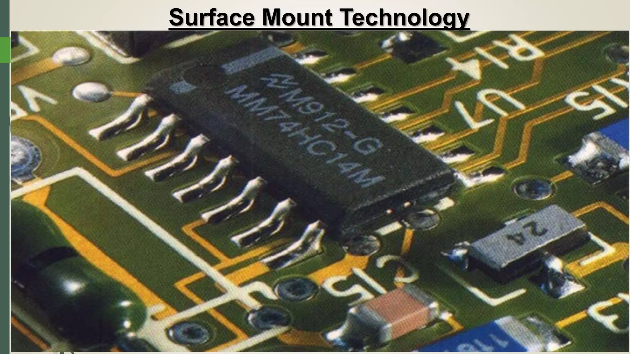
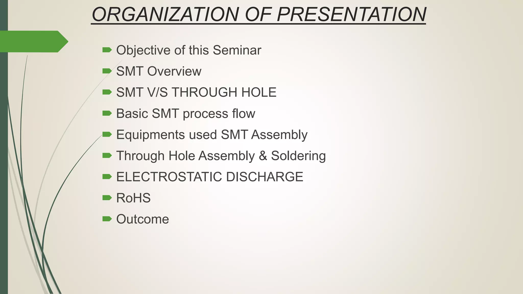
Introduction of the seminar presented by Mr. Abdul Munaff on Surface Mount Technology.
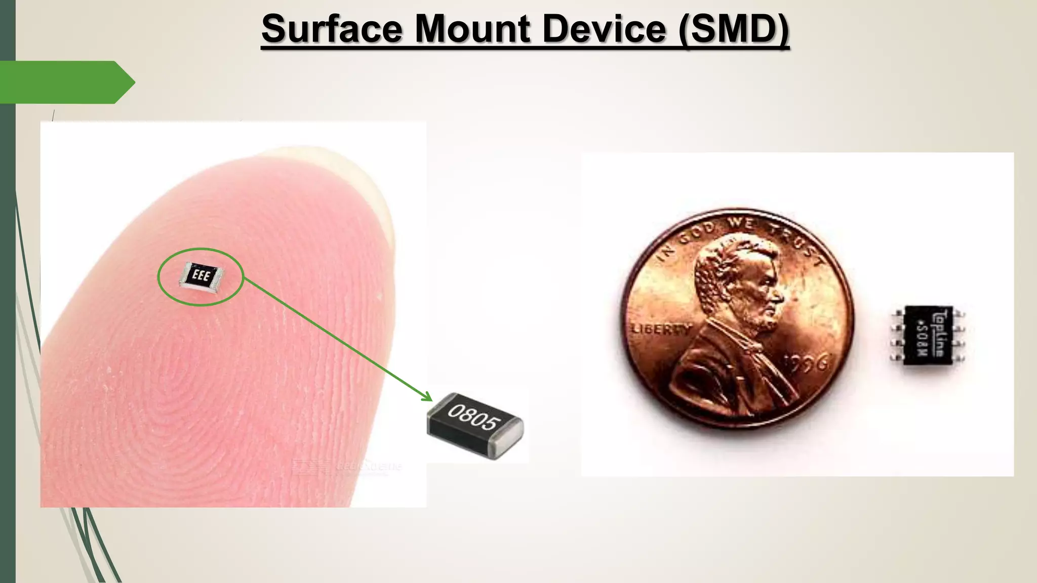
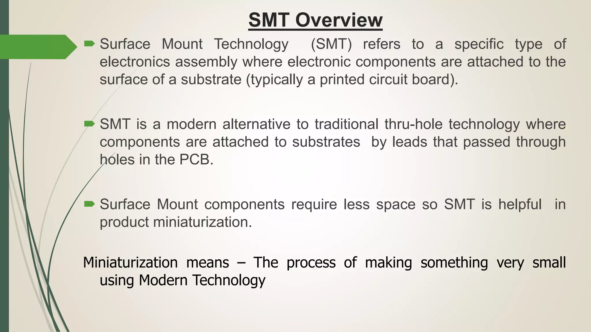
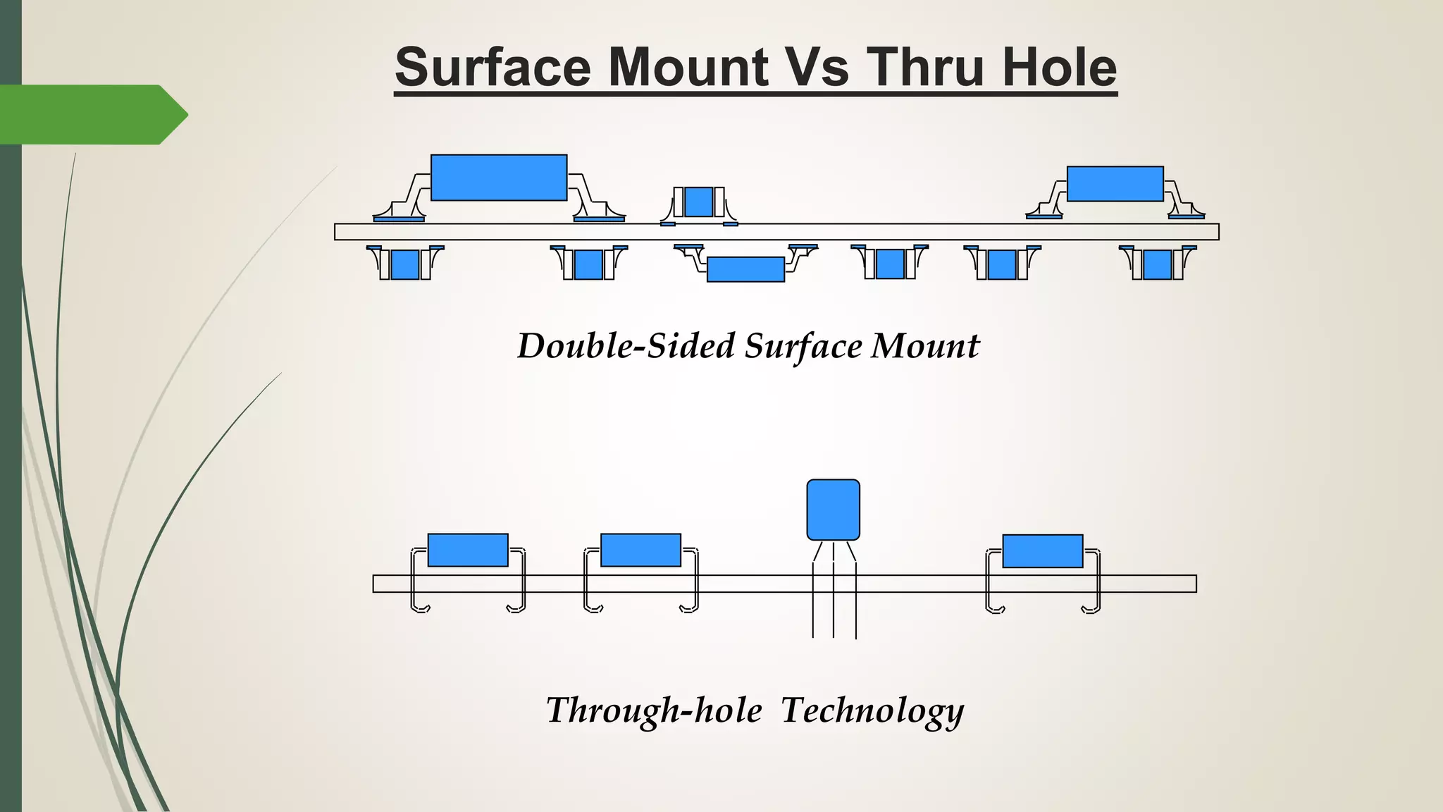
Focus on Surface Mount Devices (SMD) and the advantages of SMT over traditional methods, emphasizing miniaturization.
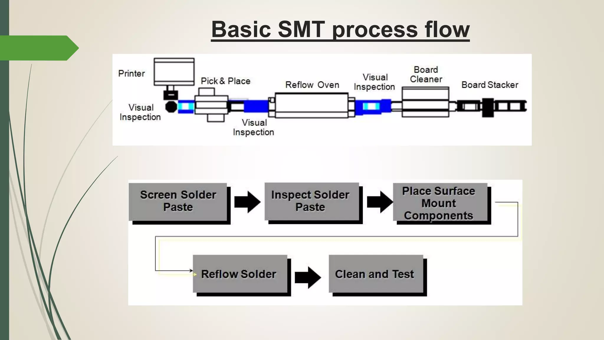
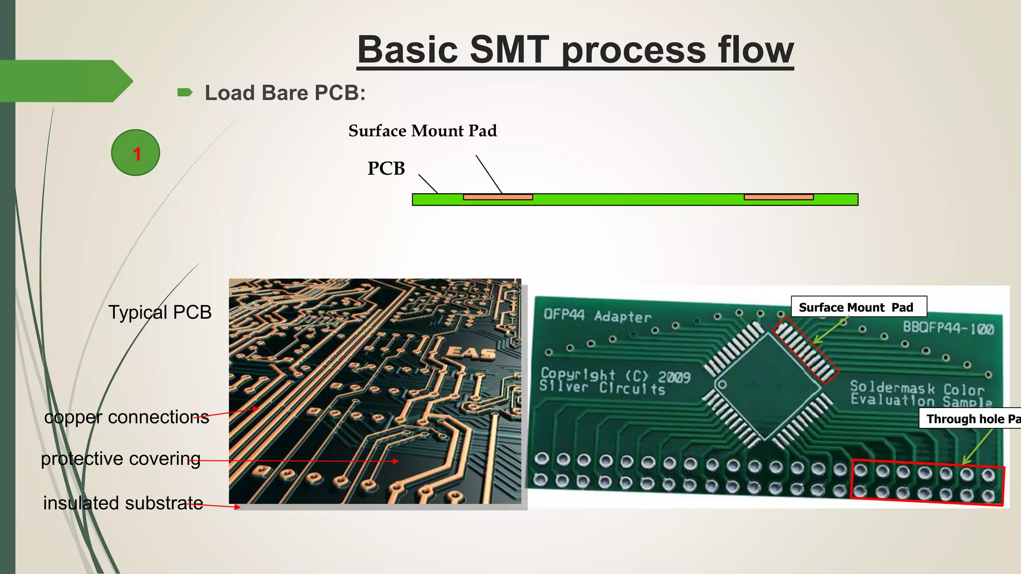
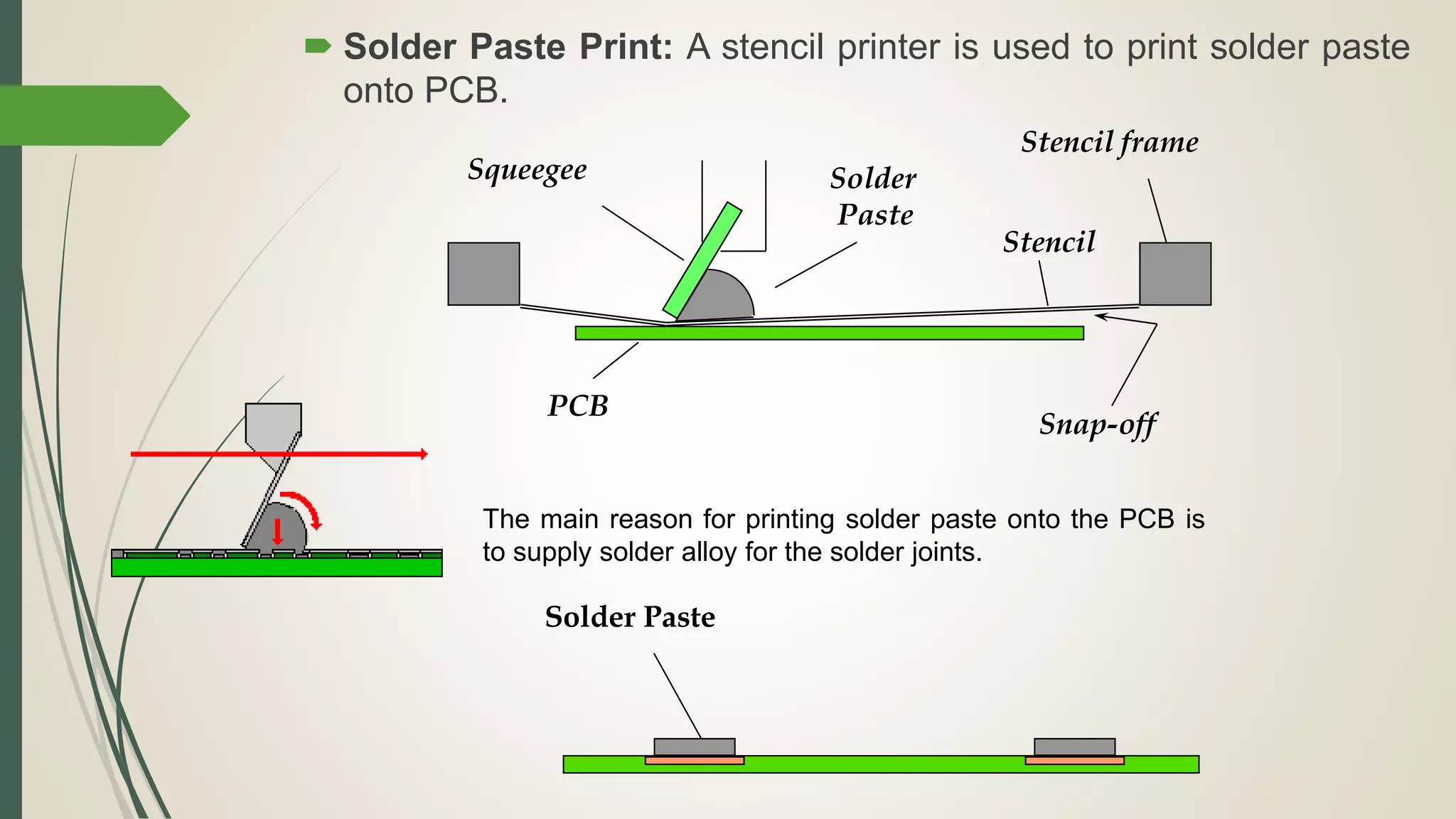
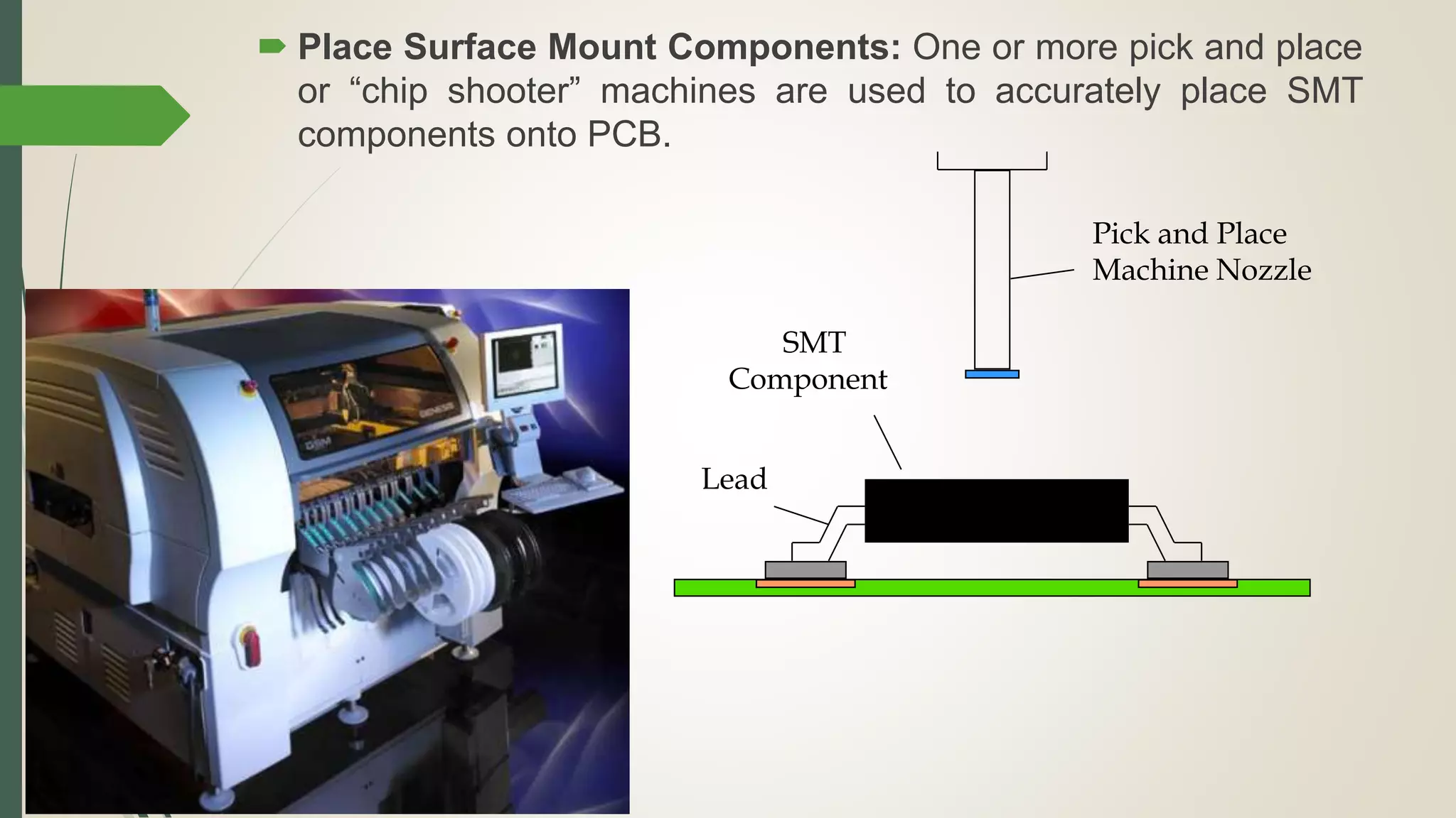
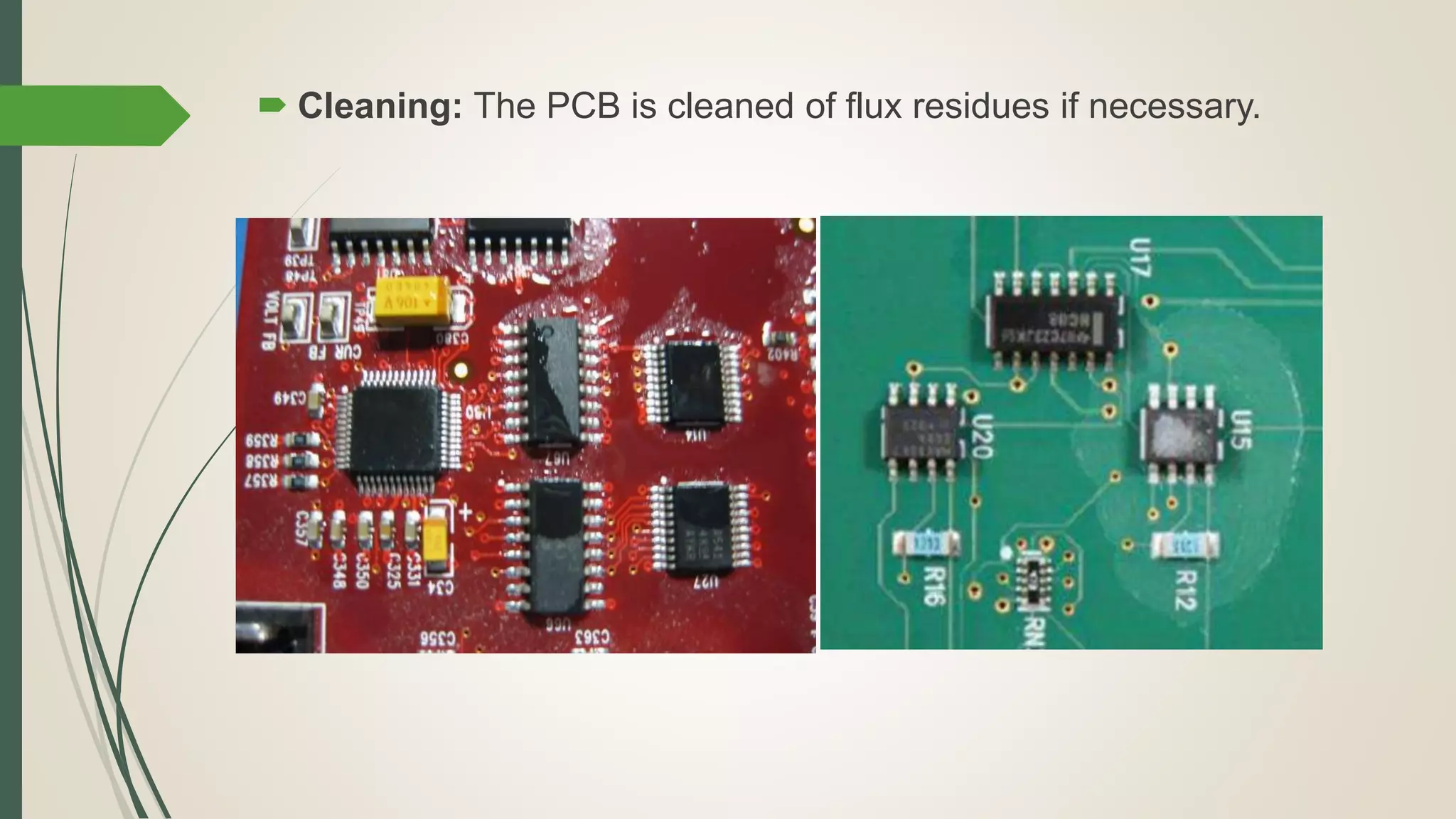
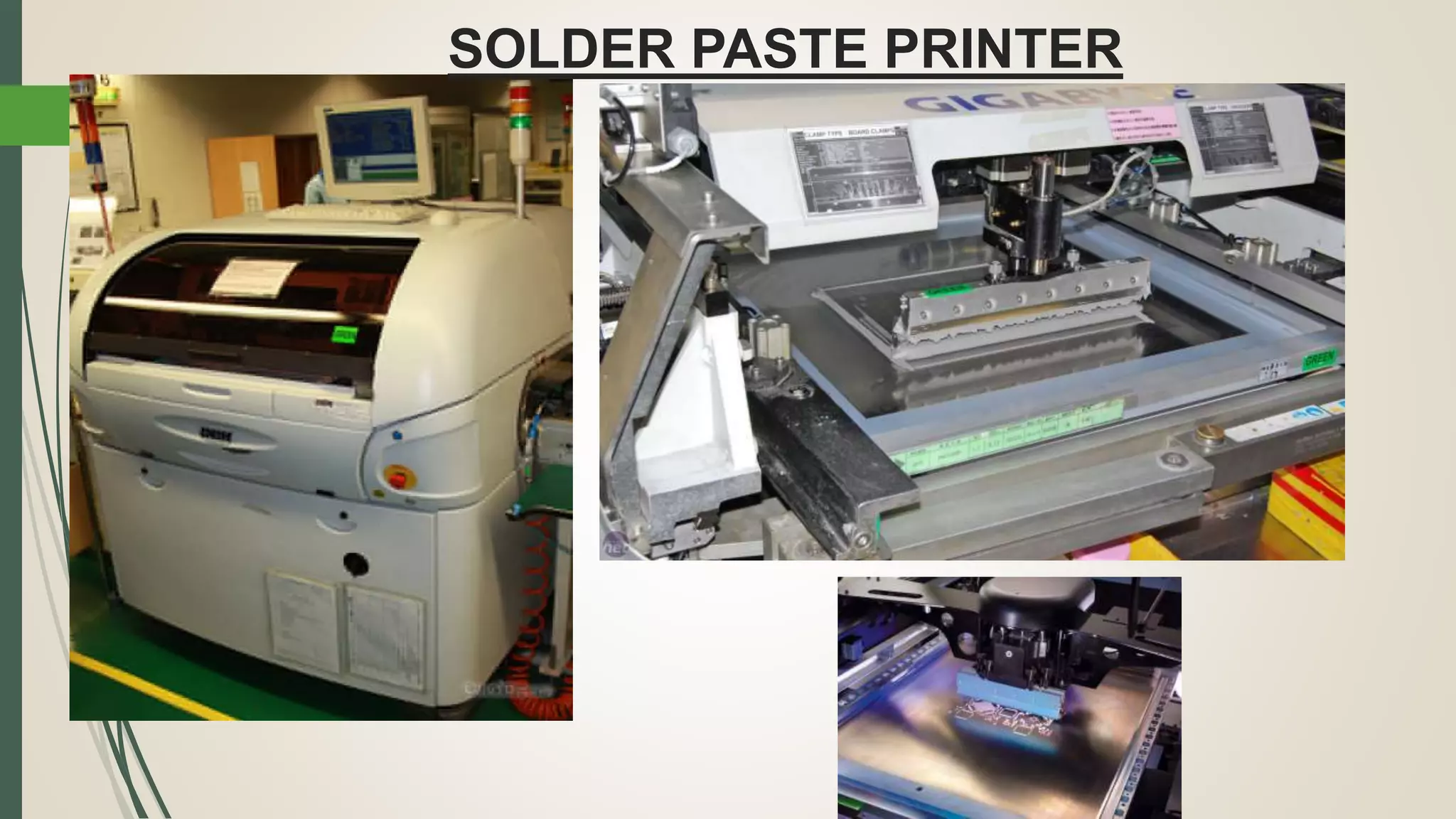
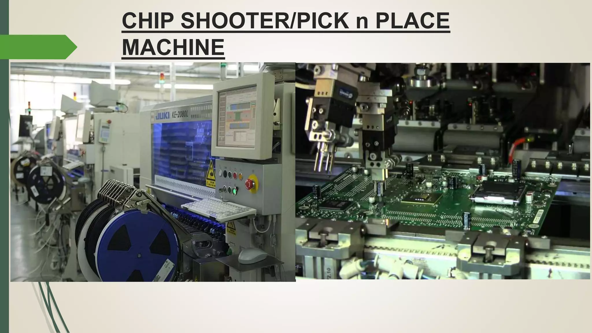
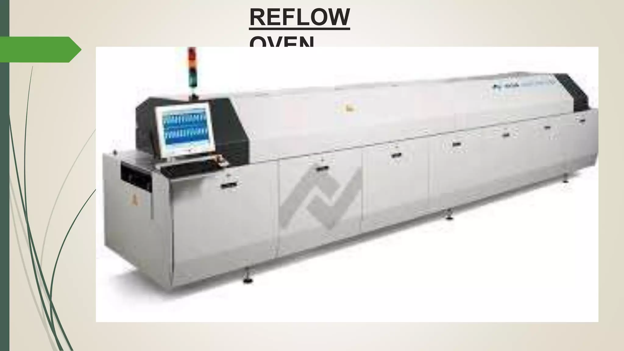
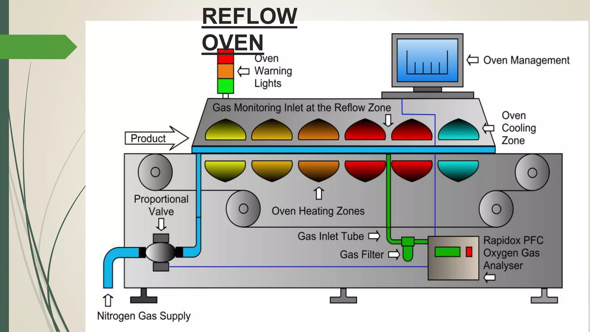
Steps involved in SMT including loading PCB, solder paste printing, component placement, and cleaning.
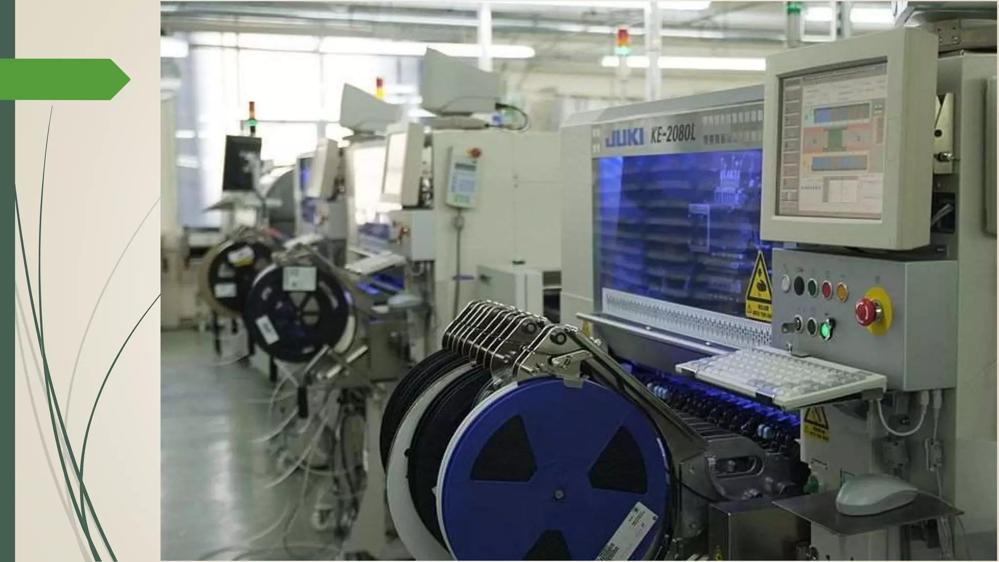
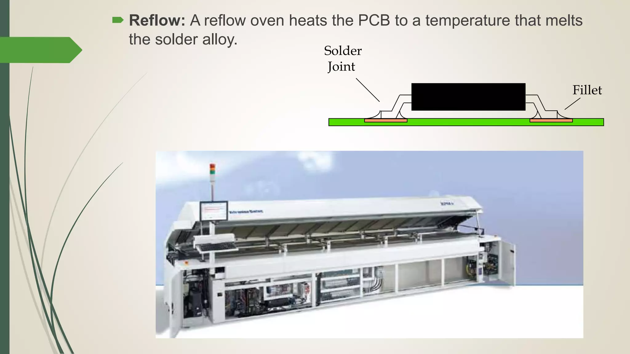
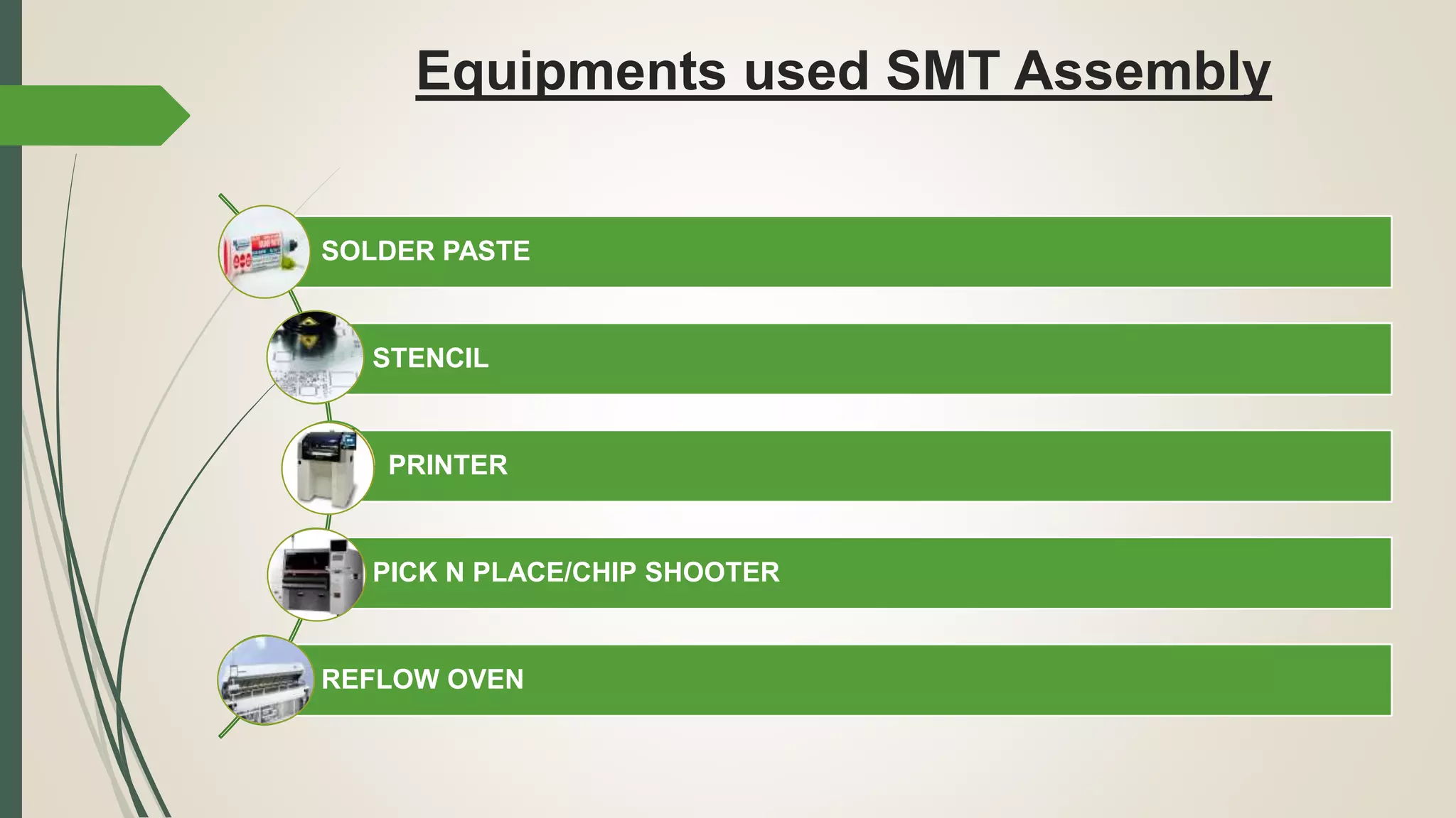
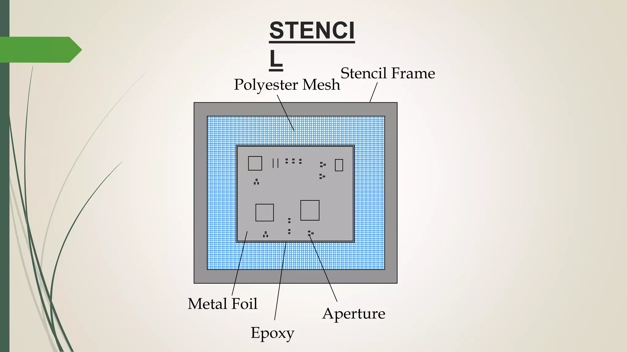
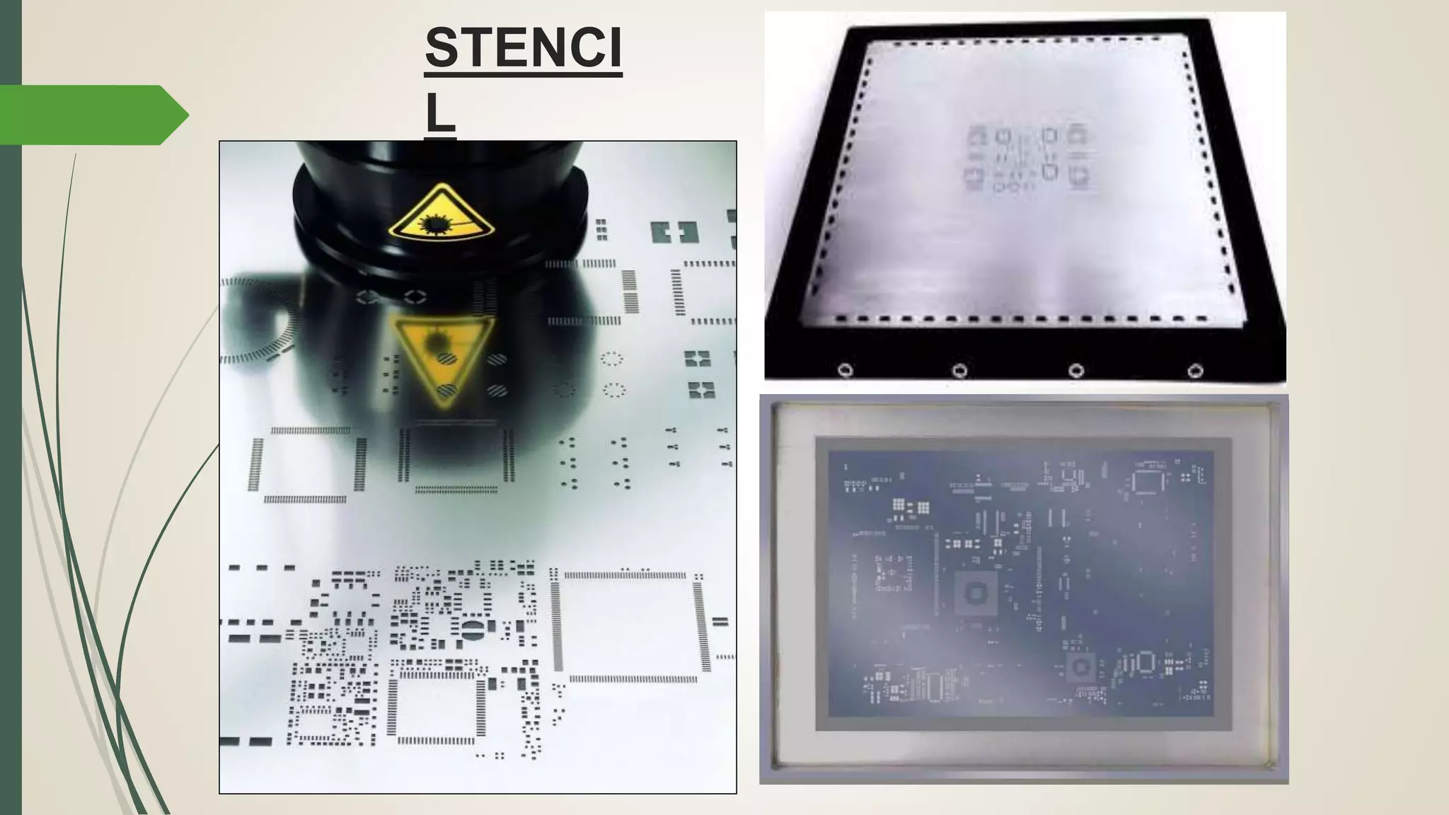
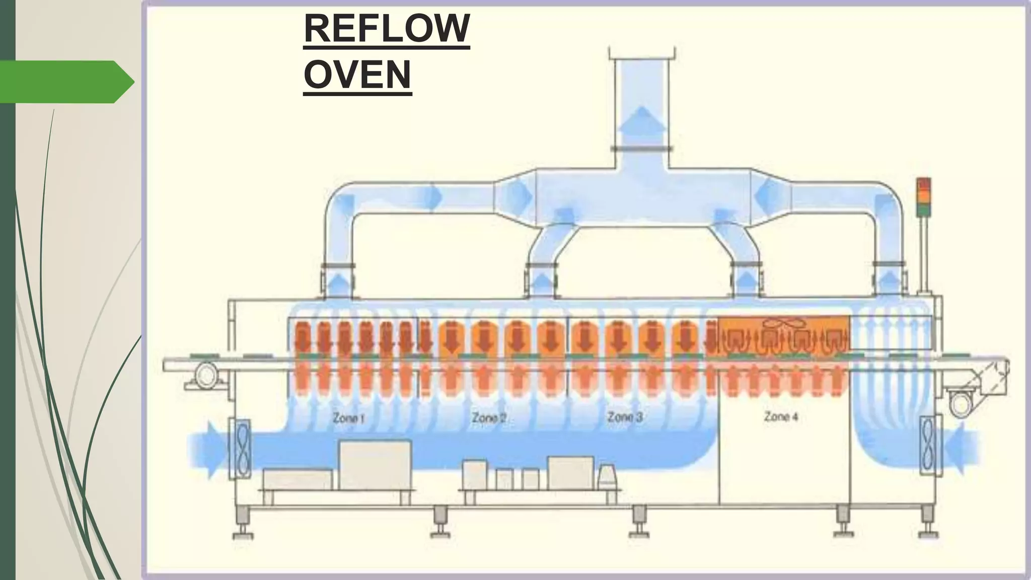
Key equipment used in SMT assembly such as solder paste printers, pick and place machines, and reflow ovens.
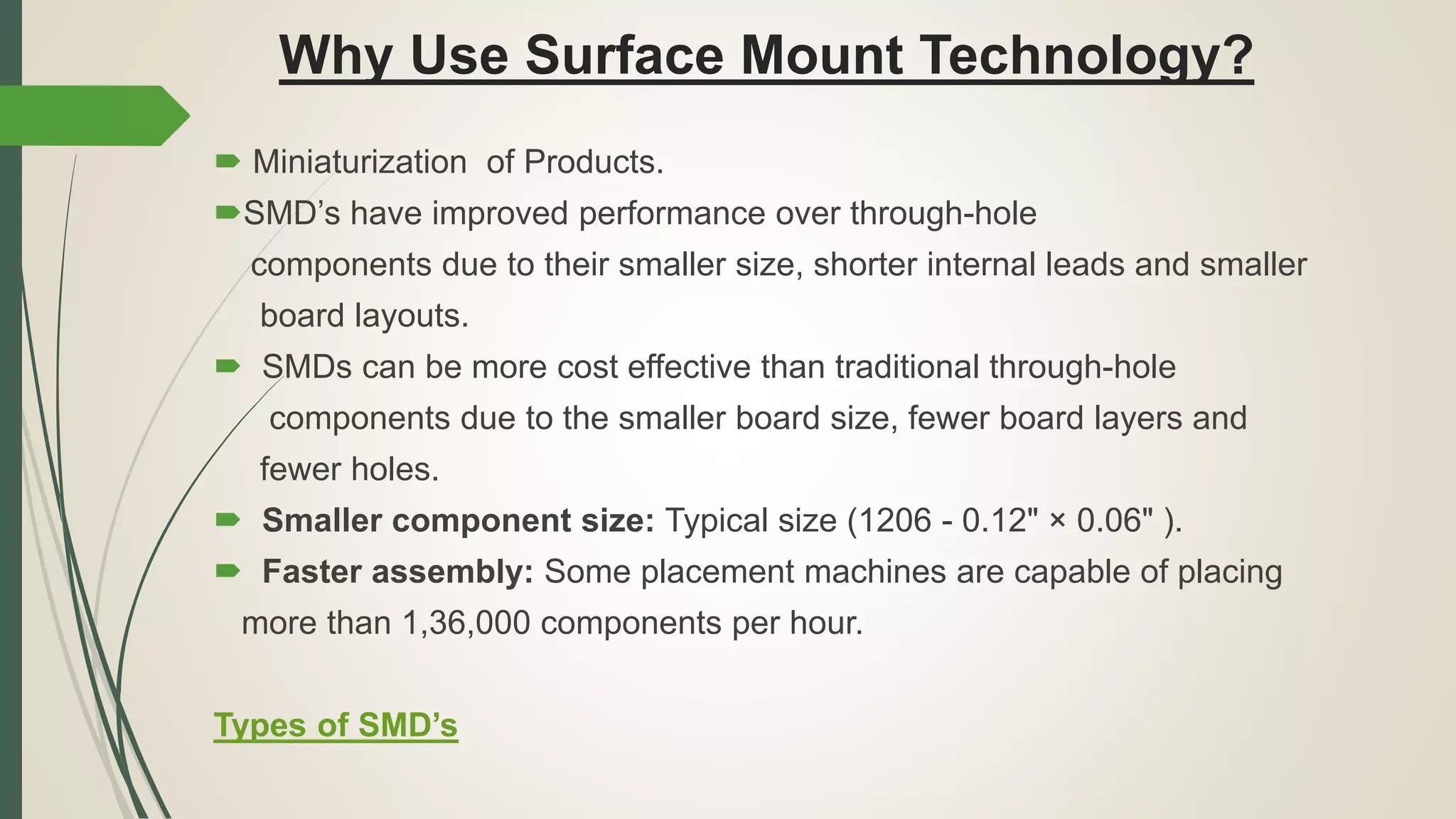
Benefits of using SMDs including miniaturization, performance improvements, cost-effectiveness, and faster assembly.
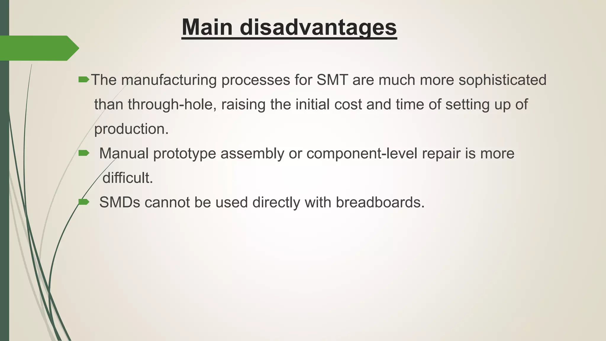
Challenges related to SMT such as higher production setup costs and difficulty in manual repairs.
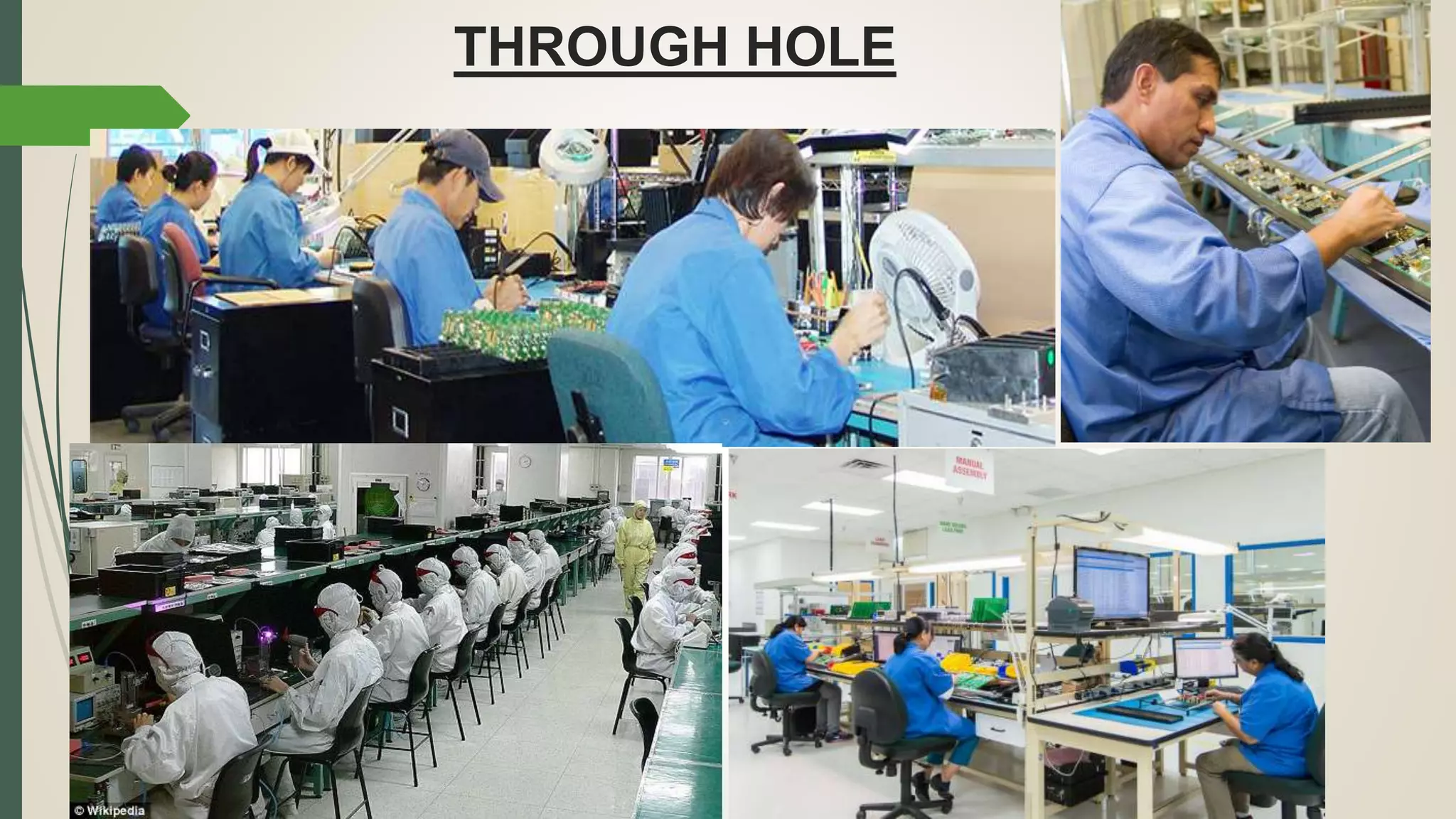
General reference to through-hole technology.
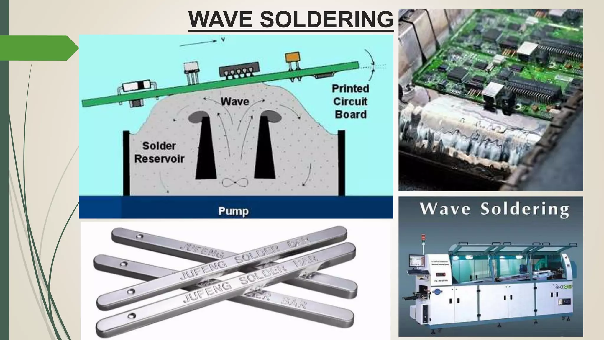
Introduction to wave soldering techniques used in through-hole assembly.
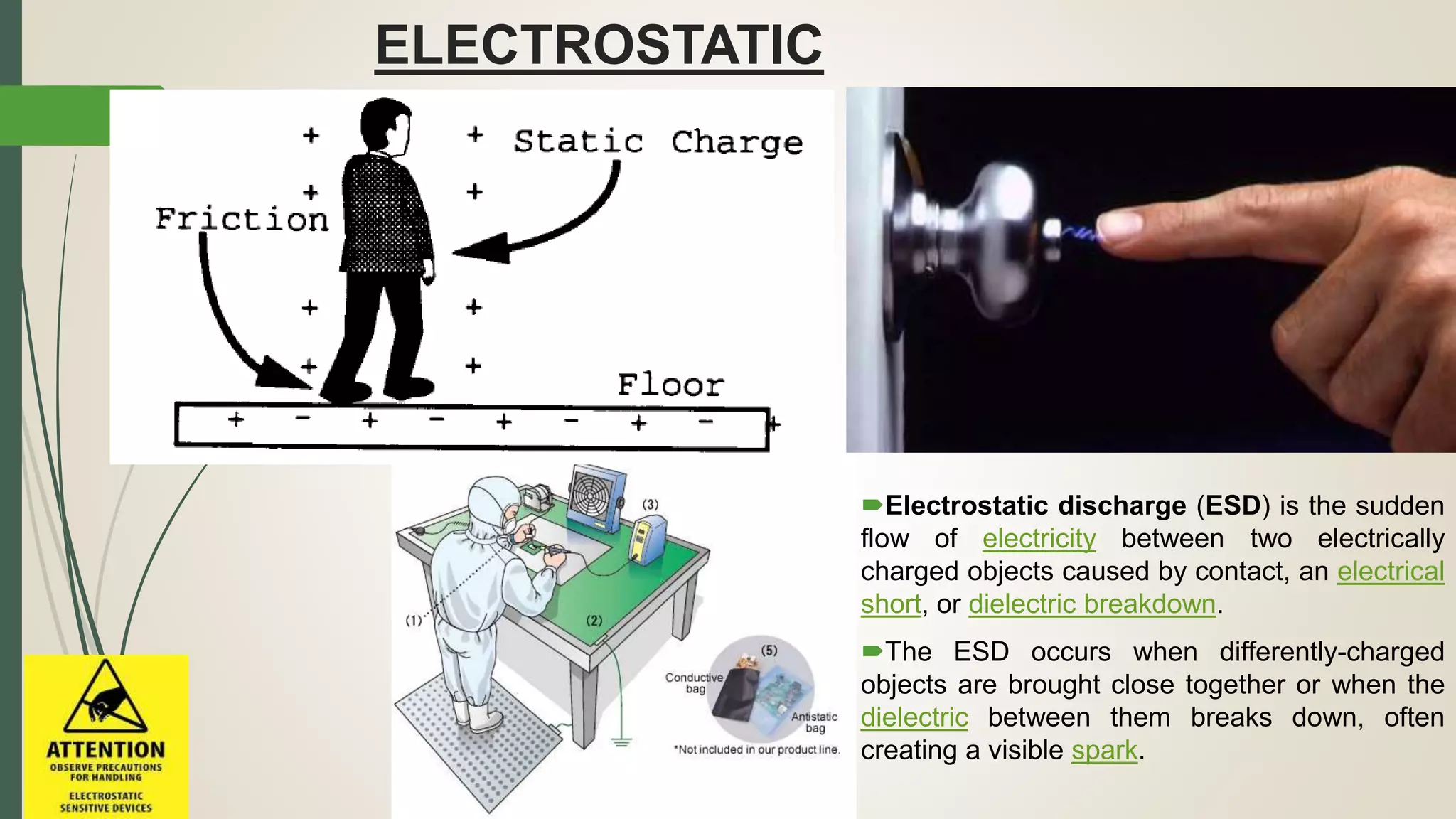
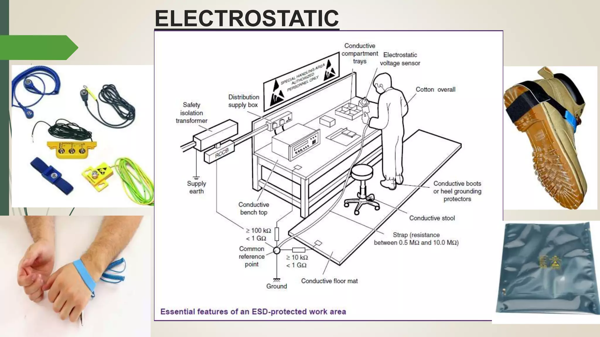
Explanation of electrostatic discharge and its significance in electronics.
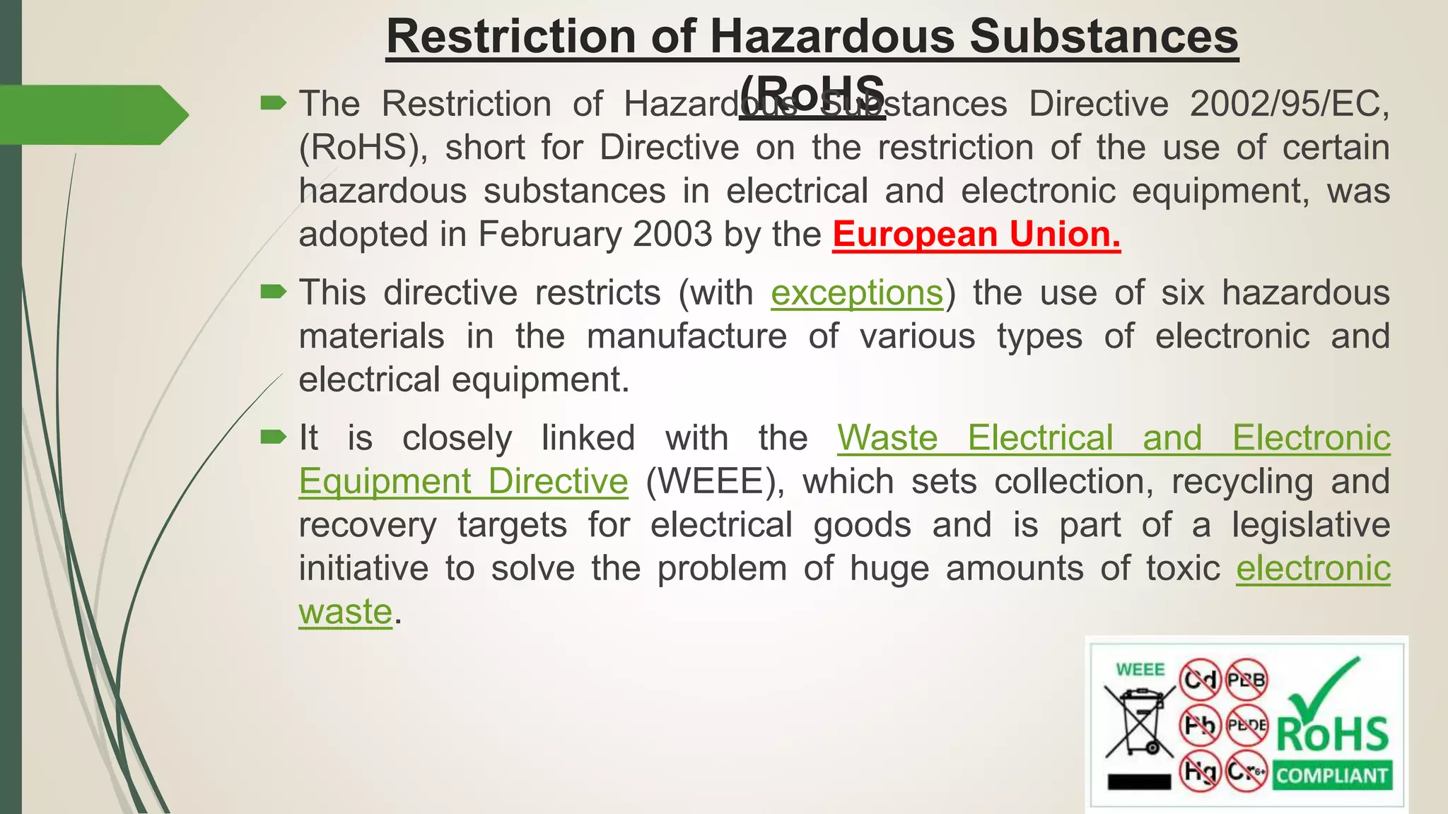
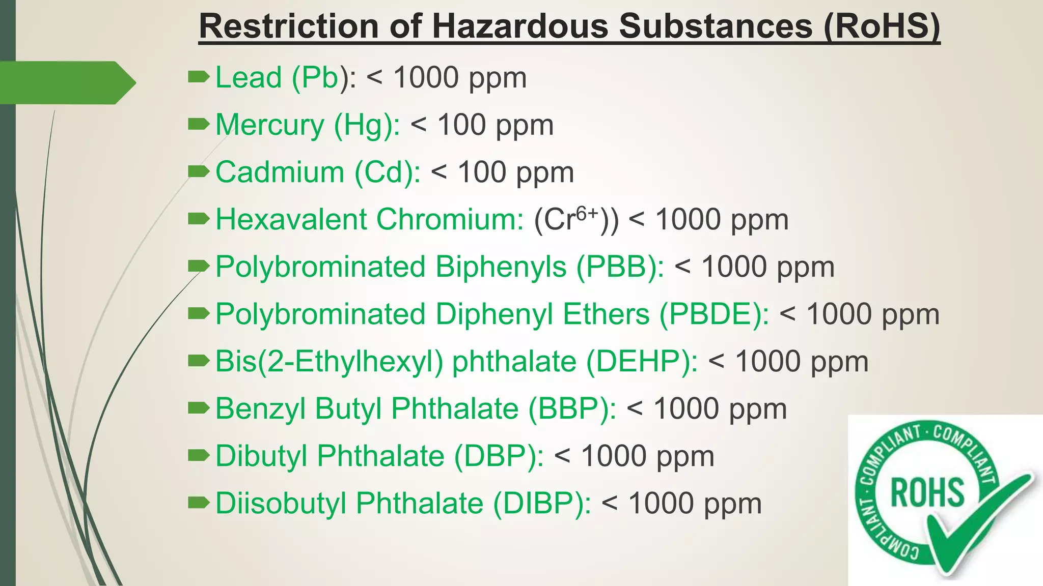
Details on RoHS legislation which restricts hazardous substances in electronic equipment.
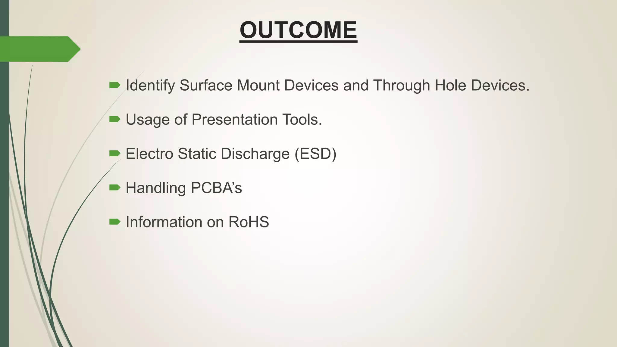
Summary of the learning outcomes including identification of certain devices and information on ESD and RoHS.
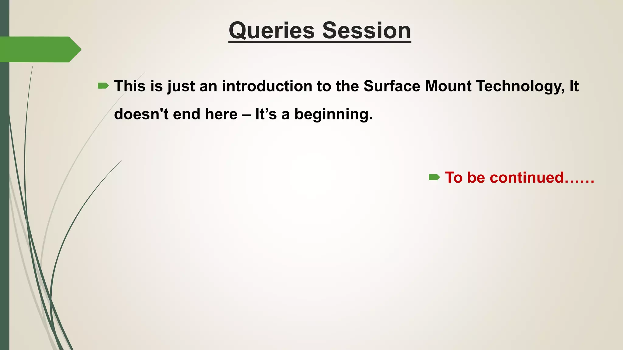
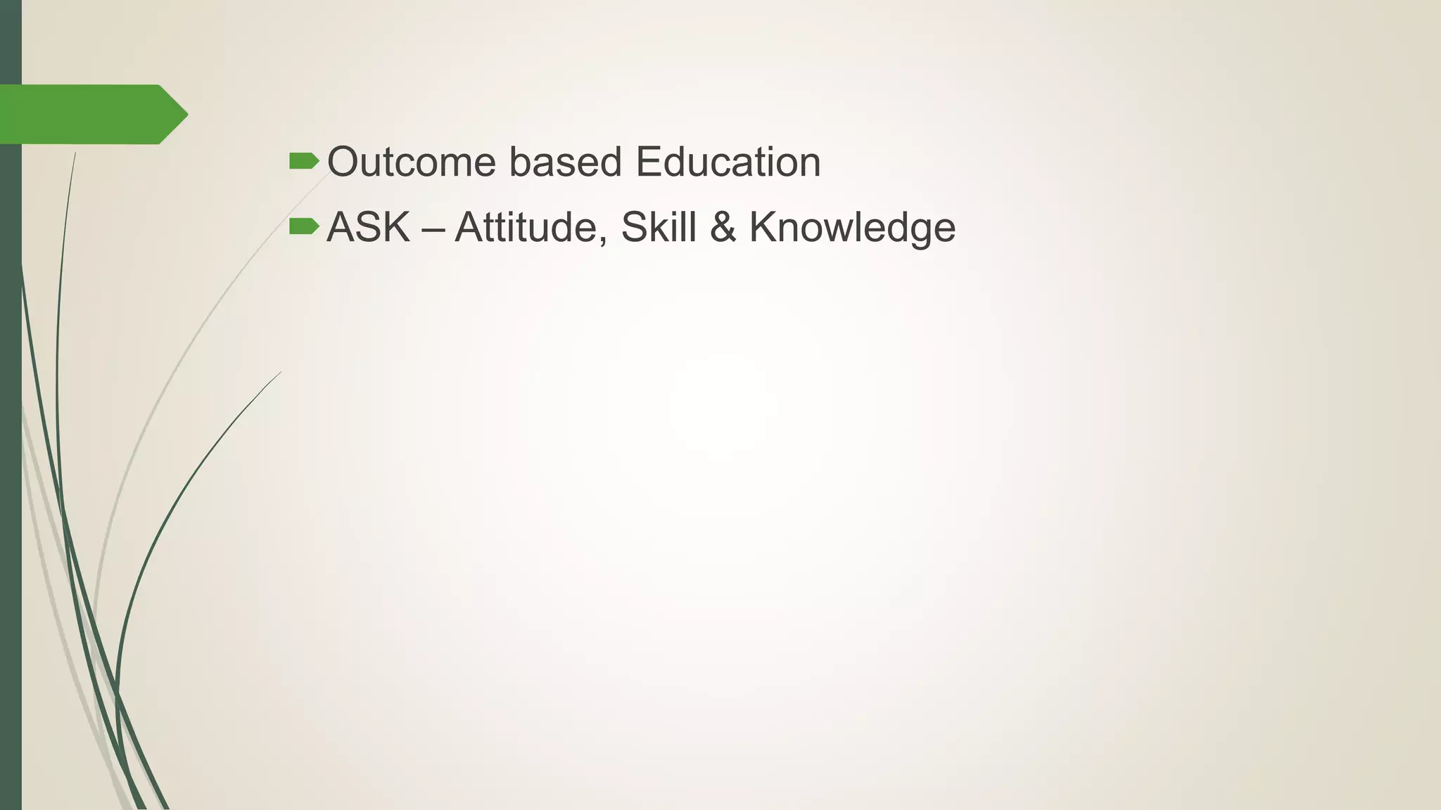
Open session for queries and mention of continued learning in SMT with emphasis on outcome-based education.