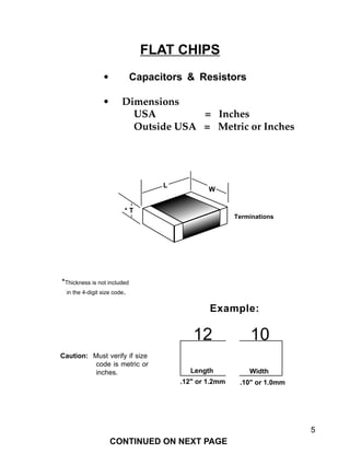
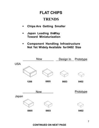
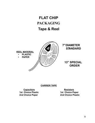
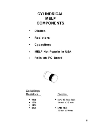
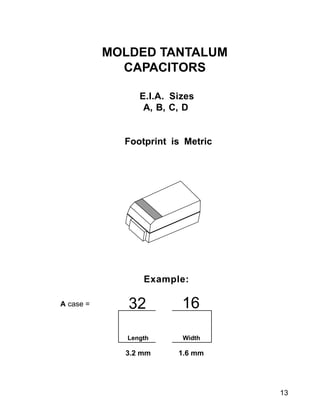
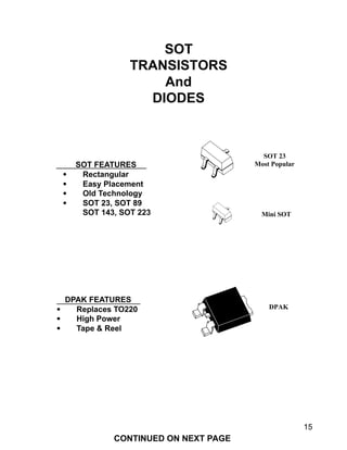
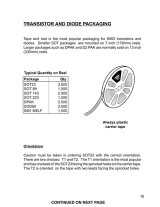
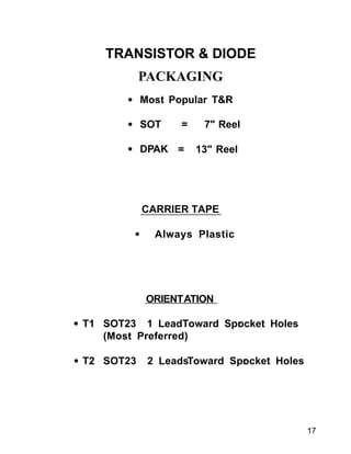
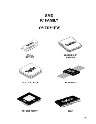
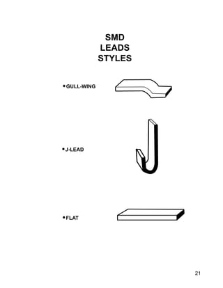
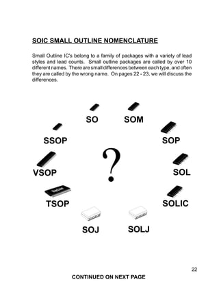
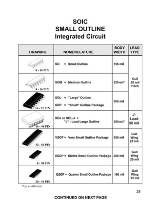
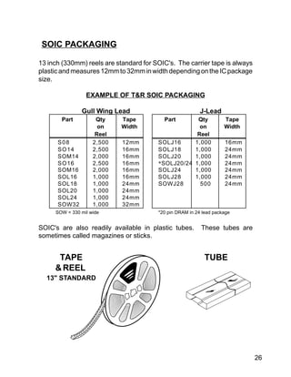
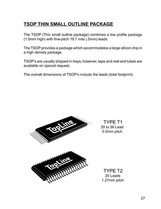
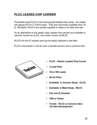
This document provides an overview of surface mount component nomenclature and packaging. It discusses the terminology used for different surface mount packages such as flat chips, MELF components, tantalum capacitors, transistors, diodes, and integrated circuits. It also describes common packaging methods such as tape and reel and trends toward smaller component sizes and higher lead densities.
Cardiology 1.1. Chest pain - by Dr. Farjad IkramFarjad Ikram
Introduction to one of the most common symptoms that can represent a wide range of diseases, from benign to life-threatening, covering number of systems including gastrointestinal, cardiovascular, pulmonary, musculoskeletal and psychiatric. Includes a brief explanation of anti-anginal therapy.
Template design credits - http://www.slidescarnival.com
New Approaches for Maintenance Grounding in Medium Voltage SwitchgearSchneider Electric
Copyright AIST Reprinted with Permission. Presented at the 2013 Iron and Steel Technology Conference and Exposition (AISTech 2013). Maintenance grounding is a traditional and proven method for protecting electrical workers during medium voltage switchgear maintenance. When properly applied, it eliminates dangerous differences in electric potential, and can redirect harmful current during events such as unforeseen induced voltage from motors and generators, accidental bus contact with adjacent live parts, or human error that causes equipment to be re-energized.
логопедиялық ертеңгілікке арналған сөз мерген атты интеллектуалдык ойыны 201...Asem Sarsembayeva
Тусупова Гулим Айткалиевна
Қарағанды облысы, Балқаш қаласы «Дамуы шектелген балаларға арналған облыстық №4 арнайы мектеп-интернаты» КММ мұғалім – логопеді
TY523MX - THOMAS & BETTS - Cable Tie, Ty Rap® Self Lock, Nylon| AKBAR TRADING...AKBAR TRADING
Thomas & Betts Corporation. Specifications are subject to change without notice. www.tnb.com. J3. J. Ty-Rap. ®/Ty-Fast. ®. T&B's Ty-Rap® Cable Ties
Thomas & Betts Key Products:
Ty-Rap Cable Ties
Ty-Met Cable Management Products
Cable Conduits
Cable Accessories
Fiberglass Pultrusion Profile and FRP Pultruded Profile are made from glass reinforced isophthalic polyester resin reinforced with E glass fibre and including continuous strand mat and a polyester surface veil as the surface layer.
The manufacturing of pultruded profiles is the most efficient method of forming composite materials with consistent high quality and low scrap. This combination gives excellent corrosion resistance and weatherability at an economic cost.
Pultruded composite profiles are increasing being used in a variety of applications. With the high strength, low weight, non-corrosive features, fiber reinforced polymer (FRP) pultrusions are rapidly growing in demand.
Magnetic contactors and magnetic starters ms-t series dienhathe.orgDien Ha The
Khoa Học - Kỹ Thuật & Giải Trí: http://phongvan.org
Tài Liệu Khoa Học Kỹ Thuật: http://tailieukythuat.info
Thiết bị Điện Công Nghiệp - Điện Hạ Thế: http://dienhathe.vn
PTH and SMT Component identification and understandingsudarshan jadwal
This slide covers SMT and PTH component identification and understanding; This is very helpful for candidate preparing for interview for electronics company.
Thomas & Betts invented and trademarked the Ty-Rap cable tie to support, fasten, bundle, clamp and manage cables and wires.
Thomas & Betts high performance Ty-Rap cable ties with integral stainless steel locking heads for industrial, hazardous area, construction and high voltage cable installations.
Thomas & Betts premium performance Ty-Rap cable ties : UV resistant, flame retardant, heat resistant, weatherproof, low and high temperature flexibility, radiation resistant (IEEE383), chemical resistant, low smoke and fume (LSF), low smoke zero halogen (LSOH), non-outgassing and metal detectable.
Thomas & Betts Ty-Rap cable ties in a choice of materials : Polyamide 6.6, Polyamide 4.6, Polyamide 12, Polypropylene, ETFE Flouropolymer, ECTFE Flourpolymer, Acetal and Stainless Steel (304 and 316 grades).
Netafim offers you all types of connector like Water Irrigation Connectors, Drip Irrigation Connectors, Irrigation Connectors, Irrigation Tubing Connectors, Drip System Connectors. Know more about drip irrigation fitting visit https://www.netafimindia.com/products-and-solutions/product-offering/connectors/
Embracing GenAI - A Strategic ImperativePeter Windle
Artificial Intelligence (AI) technologies such as Generative AI, Image Generators and Large Language Models have had a dramatic impact on teaching, learning and assessment over the past 18 months. The most immediate threat AI posed was to Academic Integrity with Higher Education Institutes (HEIs) focusing their efforts on combating the use of GenAI in assessment. Guidelines were developed for staff and students, policies put in place too. Innovative educators have forged paths in the use of Generative AI for teaching, learning and assessments leading to pockets of transformation springing up across HEIs, often with little or no top-down guidance, support or direction.
This Gasta posits a strategic approach to integrating AI into HEIs to prepare staff, students and the curriculum for an evolving world and workplace. We will highlight the advantages of working with these technologies beyond the realm of teaching, learning and assessment by considering prompt engineering skills, industry impact, curriculum changes, and the need for staff upskilling. In contrast, not engaging strategically with Generative AI poses risks, including falling behind peers, missed opportunities and failing to ensure our graduates remain employable. The rapid evolution of AI technologies necessitates a proactive and strategic approach if we are to remain relevant.
Synthetic Fiber Construction in lab .pptxPavel ( NSTU)
Synthetic fiber production is a fascinating and complex field that blends chemistry, engineering, and environmental science. By understanding these aspects, students can gain a comprehensive view of synthetic fiber production, its impact on society and the environment, and the potential for future innovations. Synthetic fibers play a crucial role in modern society, impacting various aspects of daily life, industry, and the environment. ynthetic fibers are integral to modern life, offering a range of benefits from cost-effectiveness and versatility to innovative applications and performance characteristics. While they pose environmental challenges, ongoing research and development aim to create more sustainable and eco-friendly alternatives. Understanding the importance of synthetic fibers helps in appreciating their role in the economy, industry, and daily life, while also emphasizing the need for sustainable practices and innovation.
Normal Labour/ Stages of Labour/ Mechanism of LabourWasim Ak
Normal labor is also termed spontaneous labor, defined as the natural physiological process through which the fetus, placenta, and membranes are expelled from the uterus through the birth canal at term (37 to 42 weeks
Acetabularia Information For Class 9 .docxvaibhavrinwa19
Acetabularia acetabulum is a single-celled green alga that in its vegetative state is morphologically differentiated into a basal rhizoid and an axially elongated stalk, which bears whorls of branching hairs. The single diploid nucleus resides in the rhizoid.
Read| The latest issue of The Challenger is here! We are thrilled to announce that our school paper has qualified for the NATIONAL SCHOOLS PRESS CONFERENCE (NSPC) 2024. Thank you for your unwavering support and trust. Dive into the stories that made us stand out!
Biological screening of herbal drugs: Introduction and Need for
Phyto-Pharmacological Screening, New Strategies for evaluating
Natural Products, In vitro evaluation techniques for Antioxidants, Antimicrobial and Anticancer drugs. In vivo evaluation techniques
for Anti-inflammatory, Antiulcer, Anticancer, Wound healing, Antidiabetic, Hepatoprotective, Cardio protective, Diuretics and
Antifertility, Toxicity studies as per OECD guidelines
Model Attribute Check Company Auto PropertyCeline George
In Odoo, the multi-company feature allows you to manage multiple companies within a single Odoo database instance. Each company can have its own configurations while still sharing common resources such as products, customers, and suppliers.
Francesca Gottschalk - How can education support child empowerment.pptxEduSkills OECD
Francesca Gottschalk from the OECD’s Centre for Educational Research and Innovation presents at the Ask an Expert Webinar: How can education support child empowerment?
Operation “Blue Star” is the only event in the history of Independent India where the state went into war with its own people. Even after about 40 years it is not clear if it was culmination of states anger over people of the region, a political game of power or start of dictatorial chapter in the democratic setup.
The people of Punjab felt alienated from main stream due to denial of their just demands during a long democratic struggle since independence. As it happen all over the word, it led to militant struggle with great loss of lives of military, police and civilian personnel. Killing of Indira Gandhi and massacre of innocent Sikhs in Delhi and other India cities was also associated with this movement.
3. 3
OVERVIEW
This booklet is a plain-English introduction to surface mount nomenclature
and packaging. Soon you will be speaking the language of Surface Mount
just like a professional.
1. Nomenclature
There are many different types of surface mount packages. Each time a
new surface mount package is developed a new name is created. These
names are usually abbreviated by their initials. As an example: The Quad
Flat Pack is commonly known as the QFP. Unfortunately, some packages
have more than one name. This sometimes creates confusion in the
industry. I will do my best to explain the subtle differences between
component types.
2. Package versus Packaging
Let's start by clarifying the difference between the words "package(s)" and
"packaging." The word "package" is used in this book to refer to the
component's physical shape or outline. The word "packaging" is used in
this book to describe how the component is stored. As an example: Tape
and Reel is the packaging. QFP is a package.
3. Trends
Surface mount technology changes rapidly. However, trends can be
identified. This book includes my observations of industry trends. By
understanding these trends, you will gain a fuller appreciation of the
components described in this book. They will begin to take on a life of their
own and will become more meaningful to you than just names on a page.
4. 4
FLAT CHIP NOMENCLATURE
Let's start out by studying simple flat chip components such as ceramic
capacitors and resistors.
The footprint (size) of flat chips is identified by a 4-digit size code.
In the USA, this 4-digit size code is measured in inches. Outside the USA,
the size code may be either millimeters or inches. This can cause
confusion, so it is important to verify whether the size code is in metric or
inches.
The first two digits in the size code refer to the length (L) from Termination-
to-Termination. The second two digits refer to the width (W) of the
termination.
For example, if the first two digits in the size code are 12, then the length of
the flat chip is .12". However, if the size code is metric, the 12 would equal
1.2mm.
The thickness (T) of the package is not included in the 4-digit size code. You
must refer to the actual manufacturer's data sheet to get information
regarding thickness.
Below are the most common size codes for capacitors and resistors:
Size Code Approximate Size (LxW)
Inch Metric Inch Metric
0402 1005* .04" x .02" 1.0 x 0.5mm
0504 1210* .05" x .04" 1.2 x 1.0mm
0603 1508 .06" x .03" 1.5 x 0.8mm
0805 2012 .08" x .05" 2.0 x 1.2mm
1005* 2512 .10" x .05" 2.5 x 1.2mm
1206 3216 .12" x .06" 3.2 x 1.6mm
1210* 3225 .12" x .10" 3.2 x 2.5mm
1812 4532 .18" x .12" 4.5 x 3.2mm
2225 5664 .22" x .25" 5.6 x 6.4mm
* Caution: Overlapping size codes. Metric appears same as inches.
CONTINUED ON NEXT PAGE
5. 5
FLAT CHIPS
• Capacitors & Resistors
• Dimensions
USA = Inches
Outside USA = Metric or Inches
*Thickness is not included
in the 4-digit size code.
12 10
Caution: Must verify if size
code is metric or
inches.
Example:
Length Width
W
L
* T
.12" or 1.2mm .10" or 1.0mm
Terminations
CONTINUED ON NEXT PAGE
6. 6
At the present time, component handling equipment capable of handling
0402 size components is not widely available. However, new equipment
capable of handling small sized components is rapidly being developed.
Small sized components are also more difficult to solder and service in the
field.
In fact, the 0402 is so small, it looks just like a grain of black pepper found
in your kitchen.
Japan is leading the way towards miniaturization. It is still common for
American firms to use 1206 and 0805 resistors, while most Japanese
companies use only 0805 and 0603 sizes. Americans are slowly incorpo-
rating 0603 resistors and capacitors into their new designs.
0402 is in the prototype stage in Japan, the USA and Europe.
FLAT CHIP TRENDS
CONTINUED ON NEXT PAGE
7. 7
Prototype
FLAT CHIPS
TRENDS
• Chips Are Getting Smaller
• Japan Leading theWay
Toward Miniaturization
• Component Handling Infrastructure
Not Yet Widely Available for0402 Size
Design InNow
06030805 0402
1206 0805 0603 0402
USA
Japan
PrototypeNow
CONTINUED ON NEXT PAGE
8. 8
7 inch (178mm) diameter reels are standard around the world for capacitors
and resistors. These reels can hold 5,000 resistors and typically 3,000 to
4,000 capacitors.
13 inch (330mm) reels are available on special order for higher volume
users. Thelargereel holds morecomponents(example: 10,000parts)and
requires less handling than do 7 inch (178mm) reels.
Paper (cardboard) reels with punched paper carrier tape are the most
popular packaging for resistors.
Plastic reels with embossed plastic carrier tape are the most popular
packaging choice for ceramic multilayer capacitors.
Nevertheless,capacitorsareavailablewithpapertapeandpaperreels,and
resistors are available with plastic tape and plastic reels.
For low volume assembly, bulk packaging in plastic (vinyl) bags is accept-
able.
An alternative type of packaging is now being offered by Japanese firms.
Refillablechipshooters(plasticdispensingboxes)andcasetteholdersoffer
several environmental advantages over tape and reel packaging.
Chip shooters consume less physical space and weigh less than tape and
reel. Therefore, freight charges (and gas/petrol consumption) are lower.
Since paper tape and paper reels waste trees, refillable chip shooters
conserve our forests and natural resources.
Finally, plastic tape and plastic reels are not biodegradeable and this raises
further concern over environmental issues.
FLAT CHIP PACKAGING
CONTINUED ON NEXT PAGE
9. 9
PACKAGING
FLAT CHIP
Tape & Reel
7"DIAMETER
STANDARD
13" SPECIAL
ORDER
Capacitors Resistors
1st Choice Plastic 1st Choice Paper
2nd Choice Paper 2nd Choice Plastic
CARRIER TAPE
REEL MATERIAL
• PLASTIC
• PAPER
10. 10
MELF components are more popular in Japan and Europe than in the USA.
MELF stands for Metal Electrode Face Bonded and consists of two
terminals bonded into a cylindrical body.
MELF resistors and capacitors are less expensive than their flat chip
counterparts; however, they require special handling during assembly.
The biggest disadvantage of MELF components is that they may tend to roll
off their solder pads during assembly.
Diodes are also available in MELF and mini-melf packages.
MELF COMPONENTS
CONTINUED ON NEXT PAGE
11. 11
CYLINDRICAL
MELF
COMPONENTS
• Diodes
• Resistors
• Capacitors
• MELF Not Popular in USA
• Rolls on PC Board
• 0805 • SOD 80 Mini-melf
• 1206 1.6mm x 3.5 mm
• 1406
• 2308 • SM1 Melf
2.5mm x 5.0mm
Capacitors
Resistors Diodes
12. 12
Several years ago, the electronic industry adopted the E.I.A. (American)
and I.E.C.Q. (European) standard case sizes for molded tantalum capaci-
tors.
The Japanese EIAJ standard is not fully compatible with American and
European standards.
The E.I.A. and I.E.C.Q. have established four standard case sizes. These
case sizes are designated with the lettersA, B, C, D or by their 4-digit metric
size code. Package height is not included in the size code.
EIA/IECQ Metric
Size Code Code Metric Footprint
A 3216 3.2 X 1.6mm
B 3528 3.5 x 2.8mm
C 6032 6.0 x 3.2mm
D 7343 7.3 x 4.3mm
The most common packaging for molded tantalum capacitors is plastic tape
and either plastic or cardboard reels.
MOLDED TANTALUM CAPACITORS
CONTINUED ON NEXT PAGE
14. 14
Rectangular transistors and diodes are SOT packages (Small Outline
Transistor).
The most popular size is the SOT23. Other packages include the SOT89,
SOT143 and SOT223.
The Japanese have designated the SC59 which is almost the same size as
the SOT23.
In addition, the Japanese have developed the Mini-SOT which is approxi-
mately one-half the size of a standard SOT23.
Motorola developed the DPAK and D2 PAK to house higher-powered
devices. The D2 PAK was designed to replace the popular TO220 leaded
transistor.
TRENDS
Packages for rectangular diodes and transistors are getting both smaller
and bigger.
The smallest rectangular transistor is now the mini-SOT, and it is gaining
popularity in Japan.
The biggest surface mount transistor is the D2 PAK which was developed
by Motorola to offer a direct footprint equivalent to the popular throughhole
TO220 package.
Larger packages are designed to accommodate high power silicon die.
TRANSISTORS AND DIODES
CONTINUED ON NEXT PAGE
15. 15
SOT FEATURES
• Rectangular
• Easy Placement
• Old Technology
• SOT 23, SOT 89
SOT 143, SOT 223
DPAK FEATURES
• Replaces TO220
• High Power
• Tape & Reel
SOT
TRANSISTORS
And
DIODES
DPAK
SOT 23
Most Popular
Mini SOT
CONTINUED ON NEXT PAGE
16. 16
Tape and reel is the most popular packaging for SMD transistors and
diodes. Smaller SOT packages are mounted on 7 inch (178mm) reels.
Larger packages such as DPAK and D2 PAK are normally sold on 13 inch
(330mm) reels.
Orientation
Caution must be taken in ordering SOT23 with the correct orientation.
There are two choices: T1 and T2. The T1 orientation is the most popular
andhasoneleadof theSOT23facingthesprocketholesonthecarriertape.
The T2 is oriented on the tape with two leads facing the sprocket holes.
TRANSISTOR AND DIODE PACKAGING
Typical Quantity on Reel
Package Qty
SOT23 3,000
SOT 89 1,000
SOT 143 2,000
SOT 223 1,000
DPAK 2,500
SOD80 2,500
SM1 MELF 1,500
Always plastic
carrier tape
CONTINUED ON NEXT PAGE
18. 18
Package types for surface mount integrated circuits can be grouped into
families.
The flat pack is old technology.
The QUAD flat pack and TSOP use newer technology.
Each family has certain characteristics in common such as lead style, lead
pitch, body size and case materials.
TheremainderofthisbookisdevotedtodescribingSMDintegratedcircuits.
SMD INTEGRATED CIRCUITS FAMILY
CONTINUED ON NEXT PAGE
20. 20
LEAD STYLES
Let's start by learning the three basic lead styles. Each lead has a name
which resembles its shape.
Gull-wing leads are small and quite fragile. They can easily be damaged
and must be handled with great care.
Gull-wing leads are used to get the highest number of leads onto an IC. It
is possible to get 40 to 80 leads per linear inch (15 to 33 leads per cm) onto
an IC using gull-wing leads. Gull-wing leads are easy to inspect after
soldering.
J-leads are more sturdy than gull-wing leads; however, they take up more
space. With J-leads, you can only get 20 leads per linear inch (8 leads per
cm) on an IC package.
FlatleadsarealsousedonIC's. Flatleadsmustbestoredinspecialcarriers
to prevent lead damage.
Just prior to use, IC's with flat leads are cut and bent into gull-wings by using
lead forming equipment. Lead forming equipment is an extra expense.
Therefore, flat leads are the least popular type of IC lead.
The words lead pitch are synonymous with lead space.
CONTINUED ON NEXT PAGE
22. 22
SOL
SOLIC
VSOP
SOP
TSOP
?
Small Outline IC's belong to a family of packages with a variety of lead
styles and lead counts. Small outline packages are called by over 10
different names. There are small differences between each type, and often
they are called by the wrong name. On pages 22 - 23, we will discuss the
differences.
SOIC SMALL OUTLINE NOMENCLATURE
SO
SSOP
SOJ SOLJ
SOM
CONTINUED ON NEXT PAGE
23. 23
SOIC TRENDS
The trend toward higher density (more leads) continues.
The new VSOP, QSOP and SSOP doubles the number of leads while
maintaining the traditional small outline appearance. This is accomplished
by decreasing the lead pitch from 50 mils (1.27mm) down to 25 mils (.636
mm).
Also, there is a trend to package larger silicon die into wider body SOIC's.
This is accomplished by expanding the package width from 300 mils
(7.63mm) to 330 mils (8.4mm), 350 mils (8.9mm), 400 mils (10mm) and
even 440 mils (11.1mm).
TheTSOP package combines a low profile case with high density lead pitch
of 19.7 mils (.5mm). The future looks bright for TSOP packages.
The traditional 150 mil (3.97mm) SO package and 300 mil (7.63mm) SOL
package are now commonplace in the industry.
CONTINUED ON NEXT PAGE
24. 24
SO Small Outline is the original design. It consists of a molded plastic case
measuring approximately 156 mils (3.97mm) wide, and has gull-wing leads
with 50 mils (1.27mm) lead pitch.
SOM - Small Outline Medium measures 220 mils (5.6mm) wide. SOM
packages are normally used for resistor networks.
SOL - Small Outline Large measures 300 mils (7.62mm) wide. Wider
packages measuring 330 mils, 350 mils, 400 mils and 450 mils are also
lumped into the SOL family.
SOP - Small Outline Package is a Japanese term which is used the same
way as SO and SOL.
SOJ and SOLJ - Small Outline J-Lead is used to describe SOL packages
with J-leads.
VSOP - Very Small Outline Package refers to packages with high density
25 mil (.65mm) gull-wing leads. Sometimes the term VSOP and SSOP (see
below) are interchangeable. 300 mil (7.62mm) wide body.
SSOP - Shrink Small Outline Package is the same as VSOP; however, it
has a smaller 208 mil (5.3mm) case.
QSOP-Quarter Small Outline Package are the same as the original SO
package with 25 mil pitch.
Note: The length of the body is determined by the number of leads.
SMALL OUTLINE INTEGRATED CIRCUIT (SOIC)
CONTINUED ON NEXT PAGE
25. 25
SOJ or SOL-J =
"J" - Lead Large Outline 300 mil*
SOL = "Large" Outline
300 mil
SOP = "Small" Outline Package
8 - 16 PIN
8 - 16 PIN
16 - 32 PIN
16 - 40 PIN
32 - 56 PIN
J-
Lead
50 mil
Gull
Wing
25 mil
BODY LEAD
DRAWING NOMENCLATURE WIDTH TYPE
SOIC
SMALL OUTLINE
Integrated Circuit
*Up to 440 mils
SO = Small Outline 156 mil
SSOP = Shrink Small Outline Package 208 mil
Gull
Wing
25 mil
VSOP = Very Small Outline Package 300 mil
8 - 30 PIN
20 - 56 PIN
SOM = Medium Outline 220 mil*
Gull
50 mil
Pitch
QSOP = Quarter Small Outline Package 156 mil
Gull
Wing
25 mil
CONTINUED ON NEXT PAGE
26. 26
13 inch (330mm) reels are standard for SOIC's. The carrier tape is always
plasticandmeasures12mmto32mminwidthdependingontheICpackage
size.
EXAMPLE OF T&R SOIC PACKAGING
Gull Wing Lead J-Lead
Part Qty Tape Part Qty Tape
on Width on Width
Reel Reel
S08 2,500 12mm SOLJ16 1,000 16mm
SO14 2,500 16mm SOLJ18 1,000 24mm
SOM14 2,000 16mm SOLJ20 1,000 24mm
SO16 2,500 16mm *SOLJ20/24 1,000 24mm
SOM16 2,000 16mm SOLJ24 1,000 24mm
SOL16 1,000 16mm SOLJ28 1,000 24mm
SOL18 1,000 24mm SOWJ28 500 24mm
SOL20 1,000 24mm
SOL24 1,000 24mm
SOW32 1,000 32mm
SOW = 330 mil wide *20 pin DRAM in 24 lead package
SOIC's are also readily available in plastic tubes. These tubes are
sometimes called magazines or sticks.
SOIC PACKAGING
13" STANDARD
TAPE
&REEL
TUBE
27. 27
TSOP THIN SMALL OUTLINE PACKAGE
The TSOP (Thin small outline package) combines a low profile package
(1.0mm high) with fine-pitch 19.7 mils (.5mm) leads.
The TSOP provides a package which accommodates a large silicon chip in
a high density package.
TSOP's are usually shipped in trays; however, tape and reel and tubes are
available on special request.
The overall dimensions of TSOP's include the leads (total footprint).
TYPE T1
20 to 56 Lead
0.5mm pitch
TYPE T2
20 Leads
1.27mm pitch
28. 28
PLCC LEADED CHIP CARRIER
• PLCC - Plastic Leaded Chip Carrier
• J-Lead Only
• 18 to 100 Leads
• 50 mil Pitch
• Available in Ceramic Body - CLCC
• Available in Metal Body - MLCC
• Fits Into IC Sockets
• T&R or Tubes
• Trends - PLCC is Common Item
No New Development
The plastic body PLCC is the most popular leaded chip carrier. Its J-leads
are always 50 mil (1.27mm) pitch. They are commonly available from 18
to 100 leads. PLCC's are usually supplied in tubes or on tape and reel.
As an alternative to the plastic case, leaded chip carriers are available in
ceramic, known as CLCC, and metal, known as MLCC.
PLCC's fit into IC sockets and can be easily replaced in the field.
PLCC's have been in use for over a decade and are now a common item.
29. 29
LCC LEADLESS CHIP CARRIER
The ceramic LCC is one of the most rugged packages since it has no leads
to damage. LCC's are soldered directly to PC boards by their solder pads,
knownascastellations. MostLCC'scomewith50milpitchgoldcastellations
which must be pre-coated with solder before mounting.
LCC's are usually designed for Mil Spec, aerospace and high temperature
applications.
LCC's are shipped in either trays or tubes.
Sometimes LCC's are called LCCC (Leadless Ceramic Chip Carrier).
• LCC
• Solderable Castellation Pads
• 16 Pin to 44 Pin (up to 124 pin)
• Rugged, No Leads to Bend
• Ceramic Body
• High Temp & MilSpec Applications
• Usually Tubes or Trays
30. 30
The flat pack is the oldest surface mount IC package.
Since flat packs only are available with 50 mil (1.27mm) lead pitch, they
have a low lead count such as 14, 16 or 28 leads, though some large flat
packs have up to 80 leads.
Flat packs are used only for Mil Spec, aerospace and other limited
applications.
Their flat leads must be kept straight in plastic carriers and require lead
forming just prior to use. Flat packs usually have gold leads which must be
pre-tinned prior to assembly.
It should be noted that flat packs have leads extending from only two sides
of their body. (See quad flat pack for leads extending from four sides.)
FLAT PACKS
• Usually Flat Leads
• 50 mil Pitch
• Must be Formed Prior to Use
• Mil-Spec Applications
• 10 pin to 28 (up to 80)
• Older Technology
• No Significant Trends
• Limited Applications
31. 31
QFP QUAD FLAT PACK
Quad flat packs are high lead count packages.
Quad flat packs are known as fine-pitch devices, since their lead pitch is
often 25.6 mils (.65mm) down to 11.8 mils (.3mm).
The quad flat pack family is available with many options and are called by
many names. See next page for list.
There is still development work going on with quad flat packs.
Lead counts as high as 304 leads are available.
Non-bumpered QFP's are built to Japan's EIAJ metric standard; whereas,
bumpered (BQFP's - see page 32) are built toAmerican JEDEC standards.
• EIAJ Standards (Japan)
• No Bumpers
• Gull-Wing
• 44 to 304 leads Now in Production
• .8mm to .3mm Pitch
• Usually Packaged in Trays
• T&R Special Order
CONTINUED ON NEXT PAGE
32. 32
Nomenclature
• QFP - Quad Flat Pack
• PQFP - Plastic Quad Flat Pack
• CQFP - Ceramic Multilayer QFP
• CERQUAD - Ceramic Quad Flat Pack
• MQUAD®
- Metal Quad Flat Pack
• MQFP - Metric Quad Flat Pack
• TQFP - Thin Quad Flat Pack
• TAPEPAK®
- Molded Carrier Ring
• BQFP - Bumpered Quad Flat Pack
• LQFP - Low Quad Flat Pack
There are many variations of quad flat packs depending on package
materials (plastic, ceramic or metal) and other standards.
QUAD FLAT PACK NOMENCLATURE
®TapePak is a registered trademark of National Semiconductor Corporation
®MQUAD is a registered trademark of Indy Corporation
CONTINUED ON NEXT PAGE
34. 34
The bumpered quad flat pack is built to American JEDEC standards using
true inch measurements. This means that 25 mil lead pitch is truly 25 mils
(.636mm not .65mm).
The purpose of the bumpered corners is to protect the leads during
shipping, handling and assembly.
BQFP's are constructed in a plastic package; however, they are also
available with metal case, known as the BMQUAD.
BQFP's always have gull-wing leads and are shipped in trays, tubes or on
tape and reel.
BQFP BUMPERED QUAD FLAT PACK
• JEDEC Standard (USA)
• Bumpered Corners - Protects Leads
• Gull-Wing
• Up to 196 Leads
• Package Options - Trays, Tubes and T&R
• True 25 mil (.636mm) Pitch
35. 35
TapePak® was invented by National Semiconductor and is now licensed
for production by several manufacturers.
Known for its molded carrier ring, the leads remain safe from damage. The
molded carrier ring allows the device to be tested before the need to cut and
form the leads.
Leads up to 304 are now available with TapePak.®
The main disadvantage with TapePak® is the added expense to provide
lead forming equipment.
TAPEPAK® Molded Carrier Ring
• Molded Carrier Ring
Keeps Leads Flat Prior to Use
• Allows Automated Testing
• 120 pins to 304 pins
• 25mil to 15.7mil Pitch
• 0.65mm to 0.4mm Pitch
• Coin Stack in Tubes
• Requires Lead Forming
Equipment
®TapePak is a registered trademark of National Semiconductor.
36. 37
Flip chips are bare die with small solder bumps on the bottom which
serve as "leads."
The flip chip is soldered directly to a PC Board (FR4 or ceramic) by
placing the component on the board and applying heat. The solder
bumps melt to corresponding pads on the PC Board.
The following solder type (Eutectic) is used for the bumps:
FR4 Boards 63% - 37% low melt (183ºC)
Ceramic Boards: 95% - 5% requires high temp
Bump on the die are around the perimeter and also in the middle.
Since the parts are small, dimensions are specified in "microns" not
millimeters.
100µm = 1 millimeter
Important Package Specifiers:
A. Die Size
B. Number Bumps
C. Diameter of Bumps
D. Solder Composition of Bumps
E. Bump Pitch
FLIP CHIPS
37. 39
• Coplanarity - 4 mil max (.1mm)
A setting plane is formed by the first
3 leads touching the surface.All
other leads are measured from this
plane.
• Sweep - Sideways Bending of
Gull-Wing Leads
• Tweeze -The Inward Bending of
Gull-Wing Leads
• Caution! Use Metric Footprints
.65mm ≠ 25 mil (25.6 mil)
.5mm ≠ 20 mil (19.7 mil)
.4mm ≠ 15 mil (15.7 mil)
.3mm ≠ 12 mil (11.8 mil)
FINE PITCH TERMINOLOGY