


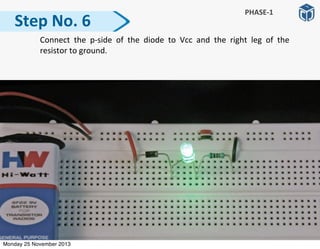
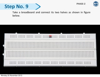


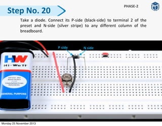
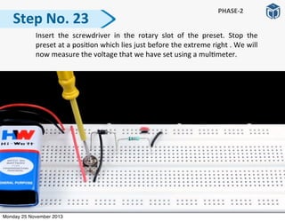
![Again,
insert
the
screwdriver
in
the
rotary
slot
of
the
preset
and
rotate
the
preset
to
its
extreme
le].
Measure
the
voltage
at
this
posi:on
using
a
mul:meter.
Step
No.
16
PHASE-‐2
Monday 25 November 2013](https://image.slidesharecdn.com/tolearnhowadiodeworks-pp-140317230314-phpapp02/85/Project-Sample-To-Learn-How-a-Diode-Works-27-320.jpg)

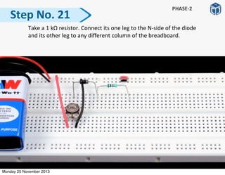

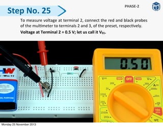


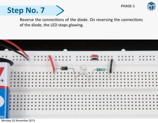
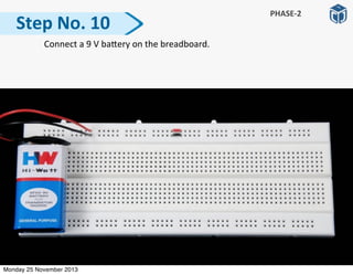
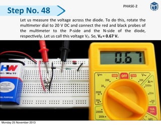
![To
measure
the
current,
connect
the
red
and
black
probes
to
the
N-‐
side
and
the
le]
leg
of
the
resistor,
respec:vely.
Since
the
mul:meter
dial
is
on
20m
posi:on,
the
current
in
the
circuit,
I1
=
0.04
mA
=
0.00004
A
≅
0
A.
Step
No.
29
PHASE-‐2
Monday 25 November 2013](https://image.slidesharecdn.com/tolearnhowadiodeworks-pp-140317230314-phpapp02/85/Project-Sample-To-Learn-How-a-Diode-Works-42-320.jpg)
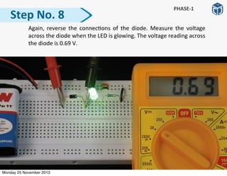
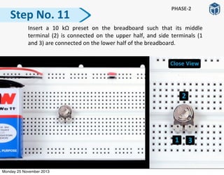
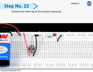
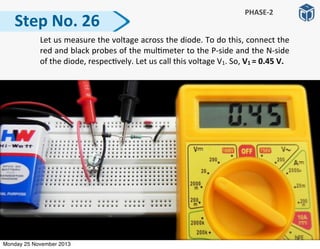
![Reconnect
the
N-‐side
of
the
diode
to
the
le]
leg
of
the
resistor.
Step
No.
30
PHASE-‐2
Monday 25 November 2013](https://image.slidesharecdn.com/tolearnhowadiodeworks-pp-140317230314-phpapp02/85/Project-Sample-To-Learn-How-a-Diode-Works-43-320.jpg)
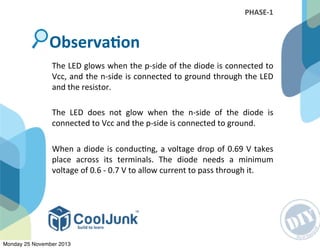
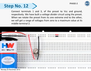
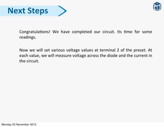
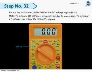
![Insert
the
screwdriver
in
the
rotary
slot
of
the
preset.
Rotate
the
preset
slowly
in
an
an:-‐clockwise
direc:on
(towards
le])
and
stop
rota:ng,
a]er
giving
it
a
slight
rota:on.
Measure
the
output
voltage
at
terminal
2
of
the
preset
using
a
mul:meter.
Step
No.
31
PHASE-‐2
Monday 25 November 2013](https://image.slidesharecdn.com/tolearnhowadiodeworks-pp-140317230314-phpapp02/85/Project-Sample-To-Learn-How-a-Diode-Works-44-320.jpg)


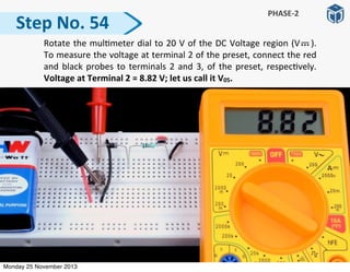
![Step
No.
37
PHASE-‐2
To
measure
the
current,
connect
the
red
and
black
probes
to
the
N-‐
side
and
the
le]
leg
of
the
resistor,
respec:vely.
Since
the
mul:meter
dial
is
on
20m
posi:on,
the
current
in
the
circuit,
I2
=
0.46
mA.
Monday 25 November 2013](https://image.slidesharecdn.com/tolearnhowadiodeworks-pp-140317230314-phpapp02/85/Project-Sample-To-Learn-How-a-Diode-Works-50-320.jpg)
![Reconnect
the
N-‐side
of
the
diode
to
the
le]
leg
of
the
resistor.
Step
No.
38
PHASE-‐2
Monday 25 November 2013](https://image.slidesharecdn.com/tolearnhowadiodeworks-pp-140317230314-phpapp02/85/Project-Sample-To-Learn-How-a-Diode-Works-51-320.jpg)
![Step
No.
39
PHASE-‐2
Insert
the
screwdriver
in
the
rotary
slot
of
the
preset.
Rotate
the
preset
slowly
in
an
an:-‐clockwise
direc:on
(towards
le])
and
stop
rota:ng,
a]er
giving
it
a
slight
rota:on.
Measure
the
output
voltage
at
terminal
2
of
the
preset
using
a
mul:meter.
Monday 25 November 2013](https://image.slidesharecdn.com/tolearnhowadiodeworks-pp-140317230314-phpapp02/85/Project-Sample-To-Learn-How-a-Diode-Works-52-320.jpg)


![Step
No.
44
PHASE-‐2
To
measure
the
current,
connect
the
red
and
black
probes
to
the
N-‐
side
and
the
le]
leg
of
the
resistor,
respec:vely.
Since
the
mul:meter
dial
is
on
20m
posi:on,
the
current
in
the
circuit,
I3
=
2.4
mA.
Monday 25 November 2013](https://image.slidesharecdn.com/tolearnhowadiodeworks-pp-140317230314-phpapp02/85/Project-Sample-To-Learn-How-a-Diode-Works-57-320.jpg)
![Reconnect
the
N-‐side
of
the
diode
to
the
le]
leg
of
the
resistor.
Step
No.
45
PHASE-‐2
Monday 25 November 2013](https://image.slidesharecdn.com/tolearnhowadiodeworks-pp-140317230314-phpapp02/85/Project-Sample-To-Learn-How-a-Diode-Works-58-320.jpg)
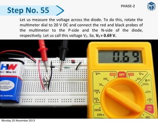
![Step
No.
46
PHASE-‐2
Insert
the
screwdriver
in
the
rotary
slot
of
the
preset.
Rotate
the
preset
slowly
in
an
an:-‐clockwise
direc:on
(towards
le])
and
stop
rota:ng,
a]er
giving
it
a
slight
rota:on.
Measure
the
output
voltage
at
terminal
2
of
the
preset
using
a
mul:meter.
Monday 25 November 2013](https://image.slidesharecdn.com/tolearnhowadiodeworks-pp-140317230314-phpapp02/85/Project-Sample-To-Learn-How-a-Diode-Works-59-320.jpg)


![Step
No.
51
PHASE-‐2
To
measure
the
current,
connect
the
red
and
black
probes
to
the
N-‐
side
and
the
le]
leg
of
the
resistor,
respec:vely.
Since
the
mul:meter
dial
is
on
20m
posi:on,
the
current
in
the
circuit,
I4
=
5.59
mA.
Monday 25 November 2013](https://image.slidesharecdn.com/tolearnhowadiodeworks-pp-140317230314-phpapp02/85/Project-Sample-To-Learn-How-a-Diode-Works-64-320.jpg)
![Reconnect
the
N-‐side
of
the
diode
to
the
le]
leg
of
the
resistor.
Step
No.
52
PHASE-‐2
Monday 25 November 2013](https://image.slidesharecdn.com/tolearnhowadiodeworks-pp-140317230314-phpapp02/85/Project-Sample-To-Learn-How-a-Diode-Works-65-320.jpg)
![Insert
the
screwdriver
in
the
rotary
slot
of
the
preset.
Rotate
the
preset
towards
the
extreme
le]
(in
an:clockwise
direc:on).
Step
No.
53
PHASE-‐2
Monday 25 November 2013](https://image.slidesharecdn.com/tolearnhowadiodeworks-pp-140317230314-phpapp02/85/Project-Sample-To-Learn-How-a-Diode-Works-66-320.jpg)

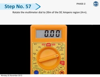
![Step
No.
58
PHASE-‐2
To
measure
the
current,
connect
the
red
and
black
probes
to
the
N-‐
side
and
the
le]
leg
of
the
resistor,
respec:vely.
Since
the
mul:meter
dial
is
on
20m
posi:on,
the
current
in
the
circuit,
I5
=
8.14
mA.
Monday 25 November 2013](https://image.slidesharecdn.com/tolearnhowadiodeworks-pp-140317230314-phpapp02/85/Project-Sample-To-Learn-How-a-Diode-Works-71-320.jpg)
![Reconnect
the
N-‐side
of
the
diode
to
the
le]
leg
of
the
resistor.
Step
No.
59
PHASE-‐2
Monday 25 November 2013](https://image.slidesharecdn.com/tolearnhowadiodeworks-pp-140317230314-phpapp02/85/Project-Sample-To-Learn-How-a-Diode-Works-72-320.jpg)


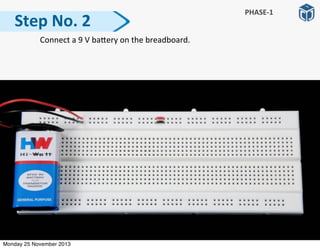
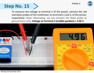
![• Ensure
that
the
baRery
voltage
is
more
than
6
volt.
• Ensure
that
the
wires
of
the
baRery
connector
are
properly
inserted
into
the
breadboard.
The
red
wire
should
be
inserted
into
the
first
row,
and
the
black
wire
into
the
second
row
of
the
breadboard.
• Ensure
that
the
pins
of
the
preset
are
properly
inserted
into
the
holes
of
the
breadboard,
and
are
not
popped
out
or
twisted.
• Press
the
preset
a]er
connec:ng
it
on
the
breadboard
so
that
its
pins
go
completely
inside
the
breadboard.
• Ensure
that
the
stripped
ends
of
the
connec:ng
wires
should
be
long
enough
to
fit
inside
the
holes
of
the
breadboard
completely.
TroubleshooGng
Tips
Monday 25 November 2013](https://image.slidesharecdn.com/tolearnhowadiodeworks-pp-140317230314-phpapp02/85/Project-Sample-To-Learn-How-a-Diode-Works-78-320.jpg)


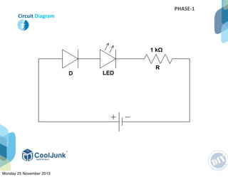
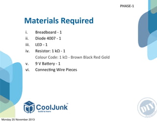
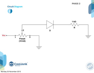
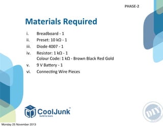
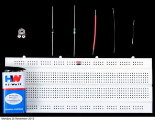
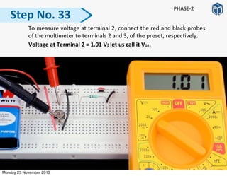
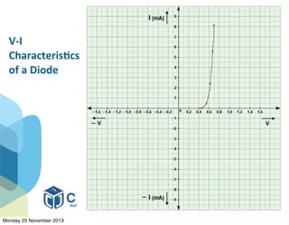
This document describes an experiment to learn how a diode works. It is conducted in two phases. In phase 1, the basic functioning of a diode is observed by connecting a diode, LED, resistor and battery in a circuit. It is observed that the LED lights up only when the diode connections allow current to flow in one direction. In phase 2, a voltage divider circuit is created using a preset resistor to vary the voltage applied across the diode. The current through the diode is then measured at different voltages to plot a graph of current vs voltage characteristics of the diode.


