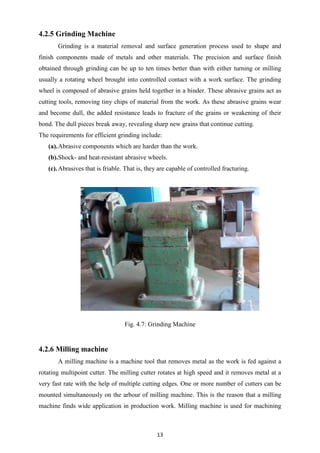
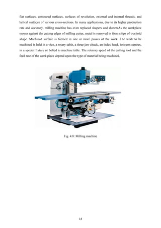
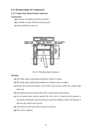
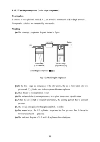
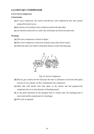
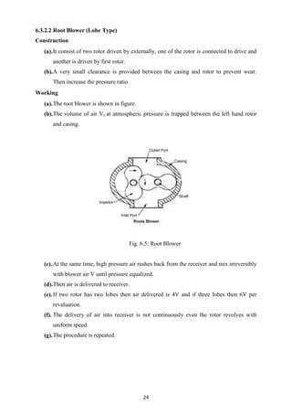
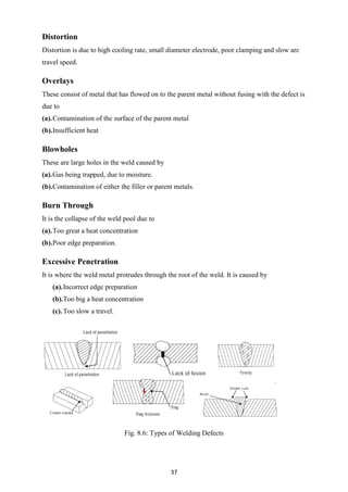
The document is a training report submitted by Virendra Kumar on his experience at the wagon repair workshop in Jhansi under the guidance of Er. Kaushal Kishore. It covers various aspects of the workshop, including its history, statistics, and detailed processes involved in wagon repair and maintenance. The report also includes acknowledgments and a declaration of originality, affirming that the work is a true record of his practical training in the field of electrical engineering.
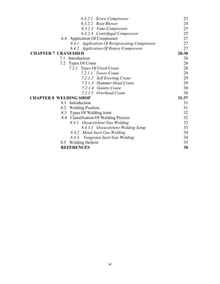

![2
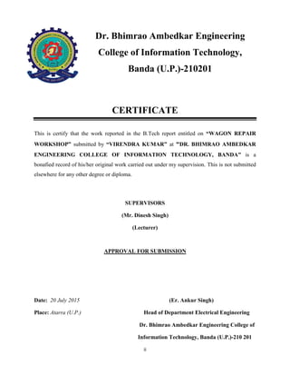
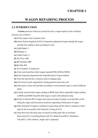
(e).1961 Introduction of Incentive Scheme.
(f). 1990 Introduction of POH of BOX ‘N’/ BCN wagons.
(g).1997 Discontinuation of coach POH.
(h).2001 ISO 9001: 2000 Certificate awarded to Jhansi workshop.
(i). 2008
[i]. Coach MLR Workshop sanctioned at a cost of Rs. 83.67 crores.
[ii].Modernization Project sanctioned at a cost of Rs. 71.44 crores.
(j). 2009
[i]. POH of Tower Wagons started on regular basis.
[ii]. Stainless Steel wagons BOXNR turned out from May 2009 Rehabilitation
[iii].Outturn increased from 50 per month in 2008-09 to 75 per month in 2009-10.
(k) 2010 GM Observation Car, RA Furnishing, RA Air conditioning
(l) 2011 Commencement of Turn Key Projects. BRN Conversion for Rail loading
DMT
(m) 2012
[i]. Conversion of BOXN to BOXNHAM started. First ever Rake of BOXNHAM in India
Railway has been flagged of on 25.05.12.
[ii]. Work of Turnkey Projects in progress, MBFU of Kanpur based ART has been
converted in to Air brake with BMBS.
1.3 STATISTICS OF JHANSI WORKSHOP
(a). Established 1895
(b). Total area 3.4 Lakh square meter
(c). Covered area 65000 square meter
(d). Approximately no. of worker 6135
(e). Total machine and plant 576+
(f). Electric load 531253KW/month
(g). Budget sanctioned 171635100 Rs/-
(h). Average wagon holding 920
(i). Total outturn per day 24.5
(j). Outturn of tank wagon 105 per month
(k). Outturn of BOX-N/BCN 476 per month
(l). Average working days of a wagon 6 days
(m). P.O.H. unit cost of wagon 260000 Rs/-](https://image.slidesharecdn.com/railwaywksp-151014183506-lva1-app6891/85/Project-Report-on-railway-workshop-Jhansi-11-320.jpg)
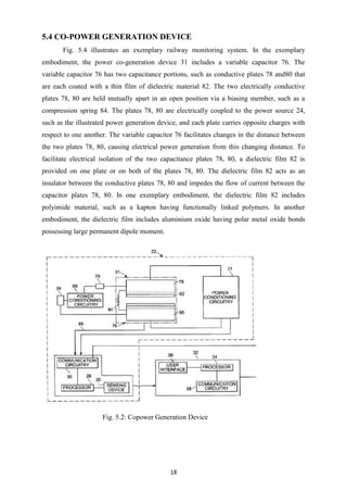
![38
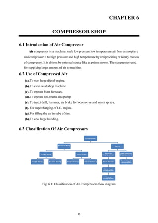
REFRENCES
[1]. http://www.ncr.indianrailways.gov.in/
[2]. http://en.wikipedia.org/wiki/North_Central_Railway_zone
[3]. http://www.fectrucks.com/fec/component/option,com_phpshop/page,shop.browse/ca
tegory_id,1/option,com_phpshop/Itemid,31/
[4]. http://science.howstuffworks.com/transport/engines-equipment/gear1.htm
[5]. http://science.howstuffworks.com/transport/engines-equipment/hydraulic-crane4.htm
[6]. http://auto.howstuffworks.com/auto-parts/brakes/brake-types/brake2.htm
[7]. http://webcache.googleusercontent.com/search?q=cache:http://ieeecss.org/CSM/libra
ry/2004/oct04/05-October2004ApplicationsofControl.pdf
[8]. http://www.escortsgroup.com/brands-and-products/construction-equipment/material-
handling-equipment.html
[9]. http://www.urmilla.in/download/Mobile-Cranes/QY50C.pdf
[10]. http://www.sciencedirect.com/science/journal/0094114X
[11]. http://www.emhcranes.com/pdf/EMH-Glossary-of-Crane-Terminology.pdf
[12]. http://en.wikipedia.org/wiki/Crane_(machine)#Mobile
[13]. http://www.stampedecrane.com/case-studies/power-transmission/](https://image.slidesharecdn.com/railwaywksp-151014183506-lva1-app6891/85/Project-Report-on-railway-workshop-Jhansi-47-320.jpg)


