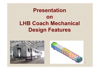
The document provides details on the design features of LHB coaches introduced on the Indian Railways network. Some key points:
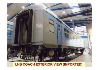
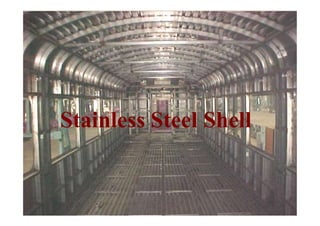
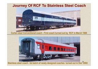
- LHB coaches were introduced in 2001 on the Shatabdi Express route, featuring stainless steel bodies, integral design, and other new technologies from the German company Linke Hofmann Busch (now Alstom LHB).
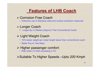
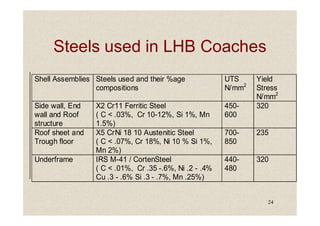
- LHB coaches are lighter, more corrosion resistant, accommodate higher speeds of up to 200 kph, and provide better ride quality and passenger comfort compared to older ICF-designed coaches.
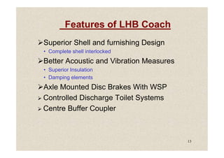
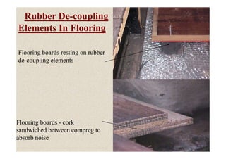
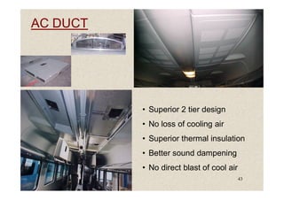
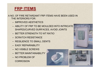
- Design improvements include extensive stainless steel construction, interlocking shell components, improved suspension, noise insulation measures, and modular/standardized interior fittings.