This document describes an integrated automated hydraulic jacking system for vehicles. The system uses two hydraulic jacks mounted on each side of the vehicle frame between the wheels. The jacks can be operated from inside the vehicle using a control panel. When activated, the jacks lift one side of the vehicle to distribute the load onto three points - the hydraulic cylinder ram and the two wheels on the opposite side. This system reduces the manual effort required to operate vehicle jacks compared to traditional screw jacks. It is powered by a hydraulic pump that supplies pressurized oil to hydraulic cylinders, which act as jacks to lift the vehicle. The system is designed to be permanently installed on the vehicle frame for easy operation during breakdowns.
Hydraulic arm (slmcop)5th sem... gulahmed ÂHméd Mêmøñ
it is a hydraulic arm which is hydraulically operated .... a very easy presentation for hydraulic arm . it is also be presented by all students other then engineering .
FLUID MECHANICS
Fluid mechanics is the branch of physics which involves the study of fluids (liquids, gases, and plasmas) and the forces on them. Fluid mechanics can be divided into fluid statics, the study of fluids at rest; and fluid dynamics, the study of the effect of forces on fluid motion. It is a branch of continuum mechanics, a subject which models matter without using the information that it is made out of atoms; that is, it models matter from a macroscopic viewpoint rather than from microscopic. Fluid mechanics, especially fluid dynamics, is an active field of research with many problems that are partly or wholly unsolved. Fluid mechanics can be mathematically complex, and can best be solved by numerical methods, typically using computers. A modern discipline, calledcomputational fluid dynamics (CFD), is devoted to this approach to solving fluid mechanics problems. Particle image velocimetry, an experimental method for visualizing and analyzing fluid flow, also takes advantage of the highly visual nature of fluid flow.
The study of fluid mechanics goes back at least to the days of ancient Greece, when Archimedes investigated fluid statics and buoyancy and formulated his famous law known now as the Archimedes' principle, which was published in his work On Floating Bodies - generally considered to be the first major work on fluid mechanics. Rapid advancement in fluid mechanics began with Leonardo da Vinci (observations and experiments), Evangelista Torricelli (invented the barometer), Isaac Newton (investigated viscosity) and Blaise Pascal (researched hydrostatics, formulated Pascal's law), and was continued by Daniel Bernoulli with the introduction of mathematical fluid dynamics in Hydrodynamica .
Fluid statics or hydrostatics is the branch of fluid mechanics that studies fluids at rest. It embraces the study of the conditions under which fluids are at rest in stableequilibrium; and is contrasted with fluid dynamics, the study of fluids in motion.
• the dynamics of fluids are the foundation of the understanding of water movement in streams and in the subsurface
• we need to understand this in order to figure out how to measure river discharge, for example
• the basic principles also apply to the flow of air, lava, glaciers, and the Earth's mantle
• we usually classify matter as either solid, liquid, or gas, based on macroscopic properties
o a gas takes on the shape and volume of a container,
o a liquid takes the shape of the portion of the container that it fills but retains a fixed volume
o a solid has its own defined shape as well as volume
• liquids and gases are called fluids
• shear stress is a tangential force per unit area acting on a surface
Hydraulic Jack is a device that uses force to lift heavy loads. The primary
mechanism with which force is applied varies, depending on the specific type of
jack, but is typically a screw thread or a hydraulic cylinder. Jacks can be
categorized based on the type of force they employ: mechanical or hydraulic.
Mechanical jacks, such as car jacks and house jacks, lift heavy equipment and are
rated based on lifting capacity (for example, the number of tons they can lift).
Hydraulic jacks tend to be stronger and can lift heavier loads higher, and include
bottle jacks and floor jacks.
Abstract: This project was discussed about the design and implementation of automated multiple water filling machine using Geneva mechanism. Generally, the function of the machine is to fill the water automatically into bottles through a moving bottle plate. This project is the combination of Geneva and electrical syncronous motor system. This project is divided into four sections, the loading section, the bottle plate section and filling section, where the whole sections is controlled by Geneva. The entire system is more flexible and time saving.
This project and implementation is very useful for long journey vehicle and this setup
helps to raise vehicle by using battery or engine power. An automatic pneumatichydraulic jack comprises a mini air compressor and automatic hydraulic jack to serve
as an on-vehicle tool where as the power of the battery on the vehicle is used to drive
the mini air compressor which compresses air to serve as its primary force. The air
enters an entry channel from an air inlet nozzle and passes to an air chamber via a
changeover valve to push a small air-oil piston, thus converting air pressure into
hydraulic pressure on the other side of the piston which enters into a large hydraulic
cylinder via a check valve and pushes a large piston. The downward movement of the
small air-oil piston causes engagement with and turns the changeover valve, thus
connecting the air chamber channel to an exhaust channel and the entry channel to the
storage tank channel which enables the oil storage tank to supply the small hydraulic
cylinder with oil under pressure and make the small air-oil piston move upwards when
the small hydraulic cylinder is filled with oil, the small air-oil piston turns the
changeover valve to connect the air entry channel to the air chamber channel again,
thereby completing the cycle. Such reciprocation converts the air pressure into
hydraulic pressure to push the big piston which in turn, jacks up the vehicle. To lower
the vehicle, an oil return screw is turned to allow the oil to return to the oil storage tank
via a return channel
It is the Presentation of Advanced fluid mechenics Topic "Impulse Turbine".Its about 12 slides.All detail about impulse turbine is given in this presentation.All photos and Videos are included in this presentation for more clearance and for more understanding.I will very helpful for all students and employees.
I just need prays and good wishes from all.Thanks.
Hope you will like it .
REVIEW ON CRITICAL SPEED IMPROVEMENT IN SINGLE CYLINDER ENGINE VALVE TRAINijiert bestjournal
The purpose of valve train is to operate the inlet and outlet valves of the engine. The valve train m ainly consists of rocker arm,push rod,cam,poppet valve and spring for kee p the valves closed position. The Greaves G400WG en gine valve train is operated at the maximum speed of 3600 rpm. The main objective of this project is to improve the valve train speed up to safe speed limit that is up to 5000 rpm. The valve spring parameters are optimized based on space availability,stress limit,stiffness,buckl ing of pushrod and natural frequency of the system. The optimized valv e spring configuration is used in the push rod type valve train and the valve train dynamics for different engine speed is studie d using commercially available multi-body dynamic A DMAS software. A comparative valve train dynamics analysis is also c arried out with the existing and optimized valve sp ring combinations. It is observed that valve jump engine speed with respect to optimized valve spring is enhanced to considerab le amount when compared to the existing valve spring configuration. Design improvements include detail study on following topi cs:1. Valve Spring Stiffness. 2. Push rod buckling. 3. Valve closing Velocity. 4. Contact stress between cam and follower
Abstract: The conventional vehicle suspension dissipates the mechanical energy i.e. potential and kinetic energy. In spring potential energy is stored and kinetic energy is wasted. The aim of paper is this wasted energy is compressed by using single acting cylinder by proper arrangement. The main aim of this paper is the compressed air production using vehicle suspension is given to the air conditioning system. The pushing power is converted into compressed air energy by proper arrangement .The pneumatic single acting cylinder is used for this project to compress the air. The output air from the pneumatic cylinder is collected through quick exhaust valve and non return valve and this compressed air stored inside the storage tank. After this research we concluded in car there is a lot of fuel burn only for working of A.C. while driving the car. If A.C. will run on other system rather than fuel then there is lot of fuel save in car hence the efficiency of car will also increases.
International Journal of Computational Engineering Research(IJCER) is an intentional online Journal in English monthly publishing journal. This Journal publish original research work that contributes significantly to further the scientific knowledge in engineering and Technology.
DESIGN IMPROVEMENTS OF VARIABLE DISPLACEMENT PUMPS-A REVIEWijiert bestjournal
In Variable displacement pump the displacement or amount of fluid pumped per revolution of
pump‟s input shaft can be varied as per requirement. This paper investigate the different
improvements achieved for increase the efficiency of variable displacement pump .This paper
also discussed about the alternative mechanisms for variable displacement pump to improve
efficiency and cost reduction of pump.
Slider Crank Mechanism for Four bar linkageijsrd.com
the slider crank mechanism is a particular four bar linkage configuration that exhibits both linear and rotational motion simultaneously. This mechanism is frequently utilized in undergraduate engineering courses to investigate machine kinematics and resulting dynamic forces. The position, velocity, acceleration and shaking forces generated by a slider crank mechanism during operation can be determined analytically. Certain factors are often neglected from analytical calculations, causing results to differ from experimental data. The study of these slight variances produces useful insight. The following report details the successful design, fabrication and testing of a pneumatically powered slider crank mechanism for the purpose of classroom demonstration and experimentation. Transducers mounted to the mechanism record kinematic and dynamic force data during operation, which can then be compared to analytical values. The mechanism is capable of operating in balanced and unbalanced configurations so that the magnitude of shaking forces can be compared. The engine was successfully manufactured and operates as intended. Data recorded by the device's accelerometers is comparable to calculated values of acceleration and shaking force.
LA HUG - Video Testimonials with Chynna Morgan - June 2024Lital Barkan
Have you ever heard that user-generated content or video testimonials can take your brand to the next level? We will explore how you can effectively use video testimonials to leverage and boost your sales, content strategy, and increase your CRM data.🤯
We will dig deeper into:
1. How to capture video testimonials that convert from your audience 🎥
2. How to leverage your testimonials to boost your sales 💲
3. How you can capture more CRM data to understand your audience better through video testimonials. 📊
Premium MEAN Stack Development Solutions for Modern BusinessesSynapseIndia
Stay ahead of the curve with our premium MEAN Stack Development Solutions. Our expert developers utilize MongoDB, Express.js, AngularJS, and Node.js to create modern and responsive web applications. Trust us for cutting-edge solutions that drive your business growth and success.
Know more: https://www.synapseindia.com/technology/mean-stack-development-company.html
Building Your Employer Brand with Social MediaLuanWise
Presented at The Global HR Summit, 6th June 2024
In this keynote, Luan Wise will provide invaluable insights to elevate your employer brand on social media platforms including LinkedIn, Facebook, Instagram, X (formerly Twitter) and TikTok. You'll learn how compelling content can authentically showcase your company culture, values, and employee experiences to support your talent acquisition and retention objectives. Additionally, you'll understand the power of employee advocacy to amplify reach and engagement – helping to position your organization as an employer of choice in today's competitive talent landscape.
Understanding User Needs and Satisfying ThemAggregage
https://www.productmanagementtoday.com/frs/26903918/understanding-user-needs-and-satisfying-them
We know we want to create products which our customers find to be valuable. Whether we label it as customer-centric or product-led depends on how long we've been doing product management. There are three challenges we face when doing this. The obvious challenge is figuring out what our users need; the non-obvious challenges are in creating a shared understanding of those needs and in sensing if what we're doing is meeting those needs.
In this webinar, we won't focus on the research methods for discovering user-needs. We will focus on synthesis of the needs we discover, communication and alignment tools, and how we operationalize addressing those needs.
Industry expert Scott Sehlhorst will:
• Introduce a taxonomy for user goals with real world examples
• Present the Onion Diagram, a tool for contextualizing task-level goals
• Illustrate how customer journey maps capture activity-level and task-level goals
• Demonstrate the best approach to selection and prioritization of user-goals to address
• Highlight the crucial benchmarks, observable changes, in ensuring fulfillment of customer needs
VAT Registration Outlined In UAE: Benefits and Requirementsuae taxgpt
Vat Registration is a legal obligation for businesses meeting the threshold requirement, helping companies avoid fines and ramifications. Contact now!
https://viralsocialtrends.com/vat-registration-outlined-in-uae/
The world of search engine optimization (SEO) is buzzing with discussions after Google confirmed that around 2,500 leaked internal documents related to its Search feature are indeed authentic. The revelation has sparked significant concerns within the SEO community. The leaked documents were initially reported by SEO experts Rand Fishkin and Mike King, igniting widespread analysis and discourse. For More Info:- https://news.arihantwebtech.com/search-disrupted-googles-leaked-documents-rock-the-seo-world/
Kseniya Leshchenko: Shared development support service model as the way to ma...Lviv Startup Club
Kseniya Leshchenko: Shared development support service model as the way to make small projects with small budgets profitable for the company (UA)
Kyiv PMDay 2024 Summer
Website – www.pmday.org
Youtube – https://www.youtube.com/startuplviv
FB – https://www.facebook.com/pmdayconference
Recruiting in the Digital Age: A Social Media MasterclassLuanWise
In this masterclass, presented at the Global HR Summit on 5th June 2024, Luan Wise explored the essential features of social media platforms that support talent acquisition, including LinkedIn, Facebook, Instagram, X (formerly Twitter) and TikTok.
1. Available online at www.scholarsresearchlibrary.com
Scholars ResearchLibrary
European Journal of Applied Engineeringand
Scientific Research,2012,1 (4):167-172
(http://scholarsresearchlibrary.com/archive.html)
ISSN: 2278 – 0041
Integrated Automated Jacksfor4-wheelers
P.S. Rana1
, P.H. Belge1
, N.A. Nagrare1
, C.A. Padwad1
, P.R. Daga1
, K.B. Deshbhratar1
N.K. Mandavgade2*
1Students of Priyadarshni College of Engineering, Nagpur, India
2Assistant Professor, Priyadarshni College of Engineering, Nagpur, India.
_____________________________________________________________________________________________
ABSTRACT
An Automobile hydraulic jack can be easily operated by a single push button provided on the dash board. The jack
will be installed on both the sides of chassis according to the weight distributions of the car. Similarly it will be
installed on the other side of the car. The system operates on hydraulic drive which consists of three main parts:
hydraulic pump, driven by an electric motor, hydraulic cylinder to lift the vehicle. The hydraulic jacks actuate
separately for either side of car as per the breakdown condition. The car gets lifted and load gets distributed on
three point i.e., plunger or ram of hydraulic cylinder and two tires opposite to side which is lifted. This jack will be
very useful for all the senior citizens and especially for females (ladies) who find it extremely difficult to operate the
jack manually in any breakdown condition. The motive behind using hydraulic system instead of a pneumatic system
is the more power produced by the system and simple in design as compared to a pneumatic design. As the hydraulic
oil is incompressible so the lifting capacity is more in comparison with the pneumatic system which operates on air
which is compressible.
Keywords- Light moving vehicles, Integrated automated jack, Hydraulic pump, Chassis.
_____________________________________________________________________________________________
INTRODUCTION
The invention relates to hydraulic jack and more specifically to an automobile hydraulic jack system. In most of the
garages the vehicles are lifted by using screw jack. This needs high man power and skilled labors
In the past both hydraulic and pneumatic jack has been utilized in combination with the structure of automobile.
They have always utilized a separate jack for each of 4 wheels by having the jacks permanently installed on the
vehicle. They are ready to operation at all time [1].
Lifting device has been installed on vehicle, such as air lifting device. Various types of jack or lift devices has been
installed on vehicle which are turned in 1 fashion or another from a horizontal attitude into a vertical attitu de and
then extended for the purpose of lifting the vehicle. It is an object of the invention to provide a novel hydraulic jack
systemthat only utilized 2 hydraulic jacks, one that is mounted on chassis on side of car between two wheels and 2
jacks that is mounted on side of automobile between its side wheels.
It is also an object of invention to provide novel jack systemthat can be operated by driver from inside the car. It is
also an object of invention to provide a novel hydraulic system in which a pump supplies pressurized oil to the
hydraulic actuator or say hydraulic cylinder which acts as a hydraulic jack which will lift the vehicle [2]. Now the
project has mainly concentrated on this difficulty, and hence such that the vehicles can be lifted from the floor land
without application of any impact force. By pressing the button in the dashboard, it activates the hydraulic jack
automatically. A Patent numbered 4,993,688, was registered dated Feb. 19, 1991, of United States by Thomas L.
167
Scholars Research Library
2. N.K. Mandavgade et al Euro. J. Appl. Eng. Sci. Res., 2012, 1 (4):167-172
______________________________________________________________________________
Mueller on Built in Power Jack. In this, there was a front suspension pneumatic jack that is mounted centrally to the
rear suspension of the automobile between its rear wheels. The system operated from a compressed air reservoir
tank that has connections for front and rear jack[3,4].
II. NEED OF INVENTION
It is believed that ‘Necessity is the mother of invention’. Here the necessity lies in reducing the human effort
applied during manual operation of the jacks and hence the need of the invention. In day to day life it is very tedious
job to operate the jack manually and it is also a very time consuming work as well. So to make it easier for everyone
especially for aged person and for lady drivers. To provide a safe and simple automatic hydraulic jacking system
without manual effort. To provide a novel jacking systemthat can be operated from within the vehicle by means of a
dashboard control panel. There are certain mechanisms already available for the same purpose which has a definite
capacity to lift the car on 2 wheels viz. a screw jack. But the general idea of the project is to minimize the human
effort while operating the jack. To provide a novel hydraulic jacking system that is directly and permanently
incorporated into the vehicle frame in such a way as to prevent the additional risk of damage or weathering.[5,6].
III. HYDRAULIC BASICS
Hydraulics is the science of transmitting force /or motion through the medium of a confined liquid. In a hydraulic
device, power is transmitted by pushing on a confined liquid. The transfer of energy takes place because a quantity
of liquid is subject to pressure. To operate liquid-powered systems, the operator should have knowledge of the basic
nature of liquids. [4]
III.1 Pascal's Law.
Blasé Pascal formulated the basic law of hydraulicsin the mid 17th century. He discovered that pressure exerted on a
fluid acts equally in all directions. His law states that pressure in a confined fluid is trans -mitted undiminished in
every direction and acts with equal force on equal areas and at right angle to a container's walls [7] as shown in fig
[1].
Figure.1Application of Pascal Law
168
Scholars Research Library
3. N.K. Mandavgade et al Euro. J. Appl. Eng. Sci. Res., 2012, 1 (4):167-172
______________________________________________________________________________
III.2 Hydraulic Systems
A hydraulic system contains and confines a liquid in such a way that it uses the laws governing liquids to transmit
power and do work and. components of a hydraulic systemthat store and condition the fluid. The oil reservoir (sump
or tank) usually serves as a storehouse and a fluid conditioner. Filters strainers and magnetic plugs condition the
fluid by removing harmful impurities that could clog passages and damage parts. Heat exchanges or coolers often
are used to keep the oil temperature within safe limits and prevent deterioration of the oil. Accumulators, though
technically sources of stored energy, act as fluid storehouses.
IV. Hydraulic Pressure,Force, and Motion
Although the force available to do work is increased by using a larger piston in one cylinder, the total movement of
the larger piston is less than that of the smaller one. When output force increases, output motion decreases. If the 10-
square-inch input piston moves 2 inches as it applies 50psi to the 100-square-inch output piston, that output piston
will move only 0.2 inch as it applies 5000 pounds of output force. The ratio of input motion to output motion is the
ratio of the input piston area to the output piston area, and you can use this simple equation to calculate it: The result
from dividing the area of the input piston (A1) by the area of the output piston is multiplied by the stroke of the
input piston or (A1 ÷ A2) × S (the input stroke) = M (the output stroke) or 10 square inches (input piston) 100
square inches (output piston) =110× 2 inches (input stroke) =0.2 inch output motion If the output piston is larger
than the input piston, it exerts more force but travels a shorter distance. The opposite also is true. If the output piston
is smaller than the input piston, it exerts less force but travels a longer distance. Apply the equation to the 5-square-
inch output piston: 10 square inches (input piston) 5 square inches (output piston) =21× 2 inches (inp ut stroke)=4.0
inches output motion. In this case, the smaller output piston applies only half the force of the input piston, but its
stroke (motion) is twice as long. These relationships of force, pressure, and motion in a brake system are easily
observed when you consider the force applied to the master cylinder’s pistons and the resulting brake force and
piston movement at the wheels. Wheel cylinder pistons move only a fraction of an inch to apply hundreds of pounds
of force to the brake shoes, but the wheel cylinder piston travel is quite a bit less than the movement of the master
cylinder piston. Disc brake caliper pistons move only a few thousandths of an inch but apply great force to the brake
rotors. This demonstrates how the use of hydraulics provides a mechanical advantage similar to that provided by the
use of levers or gears. Although hydraulic systems, gears, and levers can accomplish the same results, hydraulics is
preferred when the size and shape of the system are of concern. In hydraulics, the force applied to one piston will
transmit through the fluid, and the opposite piston will have the same force on it. The distance between the two
pistons in a hydraulic system does not affect the force in a static system. Therefore, the force applied to one piston
can be transmitted without change to another piston located somewhere else. A hydraulic system responds to the
pressure or force applied to it. The mere presence of different-sized pistons does not always result in fluid power.
The force or pressure applied to the pistons must be different in order to cause fluid power. If an equal amount of
pressure is exerted onto both pistons in a system and both pistons are the same size, neither piston will move; the
system is balanced or is at equilibrium. The pressure inside the hydraulic system is called static pressure because
there is no fluid motion. When an unequal amount of pressure is exerted on the pistons, the piston receiving the least
amount of pressure will move in response to the difference between the two pressures. Likewise, the fluid will move
if the size of the two pistons is different and an equal amount of pressure is exerted on the pistons. The pressure of
the fluid while it is in motion is called dynamic pressure. [8,9]
V. Hydraulic circuit
If we consider a hydraulic system which is used in earth moving equipments like hydraulic excavators use one and
only one power, i.e. hydraulic power. The excavators control such as bucket lifting arm swiveling, boom swiveling
and extension all this actions are controlled by hydraulic circuits. To know more about the hydraulic system we will
see it with closer view. First comes an oil tank or reservoir in which hydraulic oil is stored. The oil passes through
various pipelines and after doing useful work in an actuator the oil returns back to the oil tank. Then filter that filters
oil before going to next element, i.e. pump. Hydraulic pump which creates the flow of oil under pressure through
entire hydraulic system. Hence assist transfer of power from which we get useful work. The valves which are fluid
control element are of different types, direction control valves, flow control valves, pressure relief valves. These
valves drive the flow of oil in the system. In actuators (linear) the pressurized oil acts. The oil gives or transmits its
power to actuators to carry out work. The pipeline which is the functional connection for oil flow in the hydraulic
system. [4]
Now applying the system to lift the car from one side so that wheel will be resting on the three points, one is the
piston rod of the hydraulic actuator and the two tires. The position of each element of hydraulic system is to be
arranged in a proper manner so that it should not cause a drastic change in the four wheeler, which is now made by
the car manufacturer. The position of the hydraulic actuator is fixed. The cylinder will be permanently mounted on
the chassis centrally between two wheels on either side of the car. The oil tank or reservoir, motor and pump could
169
Scholars Research Library
4. N.K. Mandavgade et al Euro. J. Appl. Eng. Sci. Res., 2012, 1 (4):167-172
______________________________________________________________________________
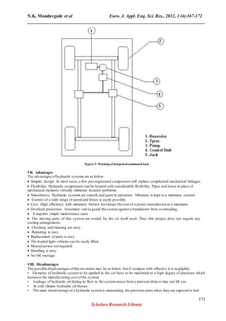
be arranged away from the cylinder as fluid is used for the transfer of the power and motion. System is represented
by fig [2].
Figure -.2Hydraulicsystems.
VI. WORKING
The actual working of hydraulic system that lifts the car takes place by single press of the button provided on
dashboard. When the switch is turned on the motor starts running which is powered by a battery already available in
the car. This motor facilitates the flow of oil which is pressurized by the pump provided. This pressurized oil id then
directed to the control unit which in turn directs the flow. Distribution of the pressurized oil is controlled by a switch
on the dashboard. As the oil proceeds into the hydraulic cylinder, it exerts a certain amount of pressure on the
plunger or the ram inside the cylinder. This exerted pressure of the oil is converted into a linear force which in turn
causes the plunger in the cylinder to move out of the cylinder. Thus ultimately the exerted pressure of the oil is
converted into linear motion of the plunger. As the plunger downwards out of the cylinder linearly, after a definite
travel of the plunger in the downward direction and once it touches the ground it starts lifting the car.
Once the car is lifted to a desired height the tires can be changed. It is the specialty of a simple hydraulic jack that it
possesses a self-locking system i.e. once the car is lifted to a certain height and even if the power to the jack is cut
off the jack can still hold the entire part of car that is lifted by it. And thus,the driver can easily change the tire.
Once the tire is changed, now the concern is to release the pressure in the jack which is in the form of pressurized
oil. Thus a relief valve is provided on the jack for this purpose. But since it is impossible to actuate this valve
manually when this jack is installed on the chassis, this valve is then provided on the dashboard of the car in form of
a switch which controls the relief valve provided on the control unit of the system. Once the relief valve is opened
the oil in the cylinder which has lost its pressure energy, starts returning to the control unit. Once the oil starts
returning the control unit then sends the accumulated oil back to the oil sump. And in this way the entire system
efficiently works.
170
Scholars Research Library
5. N.K. Mandavgade et al Euro. J. Appl. Eng. Sci. Res., 2012, 1 (4):167-172
______________________________________________________________________________
Figure 3- Workingof Integrated automated Jack
VII. Advantages
The advantages ofhydraulic systems are as below-
Simpler design. In most cases,a few pre-engineered components will replace complicated mechanical linkages.
Flexibility. Hydraulic components can be located with considerable flexibility. Pipes and hoses in place of
mechanical elements virtually eliminate location problems.
Smoothness. Hydraulic systems are smooth and quiet in operation. Vibration is kept to a minimum control.
Control of a wide range of speed and forces is easily possible.
Cost. High efficiency with minimum friction loss keeps the cost of a power transmission at a minimum.
Overload protection. Automatic valves guard the systemagainst a breakdown from overloading.
It requires simple maintenance cares
The moving parts of this system are cooled by the oil itself used. Thus this project does not require any
cooling arrangements.
.Checking and cleaning are easy.
Repairing is easy.
Replacement of parts is easy.
The loaded light vehicles can be easily lifted.
Manual power not required.
Handling is easy.
No Oil wastage.
VIII. Disadvantages
The possible disadvantages ofthis invention may be as below, but if compare with effective it is negligible.
• Elements of hydraulic system to be applied in the car have to be machined to a high degree of precision which
increases the manufacturing cost of the system.
• Leakage of hydraulic oil during its flow in the systemcauses heavy pressure drop or may not lift car.
• In cold climate hydraulic oil freezes.
• The main disadvantage of a hydraulic systemis maintaining the precision parts when they are exposed to bad
171
Scholars Research Library
6. N.K. Mandavgade et al Euro. J. Appl. Eng. Sci. Res., 2012, 1 (4):167-172
______________________________________________________________________________
climates and dirty atmospheres.
• Protection against rust, corrosion,
• Dirt, oil deterioration, and other adverse environment is very important.
REFERENCES
[1] William Cox (July 2001),"Light Talk on Heavy Jacks", Old-House Journal:
[2] Brian S. Elliott (2006), "Air-Over-Hydraulic Jacks", Compressed air operations manual, McGraw-Hill
Professional, pp. 56–58
[3] Mueller, Pamela, and Thomas L. Mueller. "Built In-Power Jack." U.S. Patent Number 4,993,688, 1991 [2].
[4] John Norman (2009), Fire Department Special Operations.
[5] Mosley, David J. "Vehicle Mounted Hydraulic Jack System." U.S. Patent Number 5,377,957,1995.
[6] Parr, Andrew. Hydraulics and Pneumatics: A Technician's and Engineer's Guide. 1st Edition. Oxford:
Butterworth-Heinemann, 1999.Print.
[7] Mueller, Pamela, and Thomas L. Mueller. "Built In-Power Jack." U.S. Patent Number 4,993,688, 1991 [2].
[8] Rodriguez, Daniel G. "Automatic Jacking Systemfor an Automotive Vehicle." U.S. Patent Number 6,991,221,
2006.
[9] Stringer, John. Hydraulic Systems Analysis:An Introduction.Hoboken: Wiley, 1976. Print.
172
Scholars Research Library