This document describes the design of a mechanical hydraulic jack. It begins with introducing the basic principles of hydraulics and how hydraulic jacks work based on Pascal's law. It then discusses the design considerations and methodology for key components of the hydraulic jack, including the ram cylinder, plunger cylinder, plunger, lever, reservoir, and base. Detailed calculations are shown for sizing each component based on the design loads, pressures, and materials. Manufacturing and inspection steps are also outlined for the ram cylinder.
![Design of Mechanical Hydraulic Jack
International organization of Scientific Research 19 | P a g e
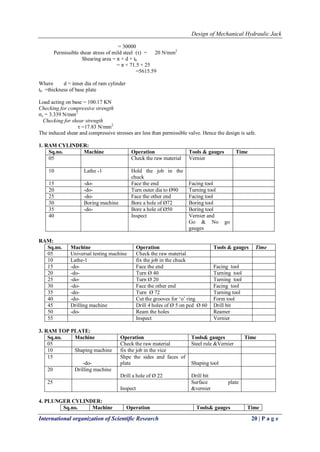
Calculation of bending moment:-
Ra + Rb = 130 kg
Ra + 20 = 130
Ra =130-20
Ra = 110 kg
Bending moment at C = 0
Bending moment at B = 20× 9.81× 0.635 = 124.58 N-m
Bending moment at A = (20× 9.81× 0.75) – (130× 9.81× 11.5) = 0
From the above calculation
Maximum bending moment = 124.58 N-m
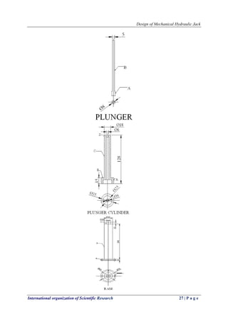
Where dl = diameter of lever
= 0.0219 m
= 21.9 mm
We adopt diameter of lever = 25 mm
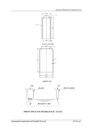
XIII. DESIGN OF RESERVOIR
The volume of oil circulated in the system is 835c.c
But, we take the volume of oil is 33% greater than the volume of circulated in the system.
Volume of oil in the reservoir = 835+ × 835
= 1110c.c
[× L]- = 1110 c.c
Where
D = outer dia of ram cylinder
L = height = 119.89 mm
We adopt inner dia of reservoir () = 122mm
Assuming thickness of reservoir () = 4mm
Therefore outer dia of reservoir (Dr) =
= 122+(2×4)
= 130mm
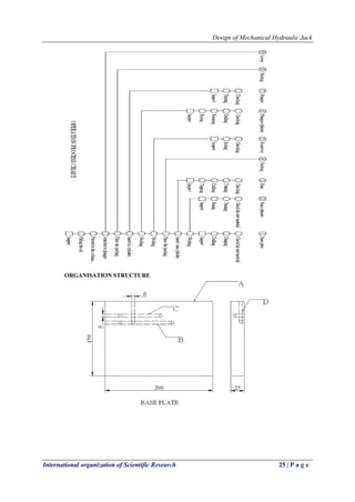
XIV. DESIGN OF BASE
Fix the dimensions of base plate as
l× b × tb = 200×150×25
Where l = length of base
b =width of base
tb =thickness of base
Base is made up of mild steel.
Permissible compressive stress of M.S (σc) = 20 N/mm2
Compressive area of base =200×150](https://image.slidesharecdn.com/d04711528-140805235819-phpapp02/85/D04711528-5-320.jpg)
![Design of Mechanical Hydraulic Jack
International organization of Scientific Research 28 | P a g e
REFERENCES
[1] Electric Scissor Jacks, Jackmaster. "Electric Scissor Jacks". Retrieved 8 February 2014.
[2] William Cox (July 2001), "Light Talk On Heavy Jacks", Old-House Journal: 37
[3] Brian S. Elliott (2006), "Air-Over-Hydraulic Jacks", Compressed Air Operations Manual, Mcgraw-
Hill Professional, Pp. 56–58, Isbn 978-0-07-147526-6
[4] George William Sutcliffe (1895), Steam Power And Mill Work Principles And Modern Practice,
Whittaker & Co., P. 828, "The Bottle-Jack Is Exceedingly Firm And Safe For Short Vertical Lifts,
But Is Not Convenient For Pushing In A Horizontal Or Oblique Direction."
[5] John Norman (2009), Fire Department Special Operations, Fire Engineering Books,
P. 51, Isbn 978-1-59370-193-2
[6] Reference Books:
[7] Strength Of Materials - A.S.Ramamrutham
[8] Applied Mechanics - R.S.Khurmi
[9] Applied Mechanics And Strength Of Materials - Dr. R.K.Bansal
[10] Applied Mechanics And Strength Of Materials - I.B.Prasad
[11] Pneumatics & Hydraulics - Harry. L. Stewart
[12] Introduction To Pneumatics - Festo Manual
[13] Fundamentals Of Pneumatic Control Engineering - Festo Manual
[14] Hydraulic Machines, Jagadishlal, , Metropolitan Book Co. Pvt. Ltd., 1, Faiz Bazaar, New Delhi –
110 006.
[15] Hydraulics,Andrew Parr (A Technician‘s And Engineer‘s Guide) Fundamentals Of Pneumatic
Control Engineering -Festo Manual
[16] Fluid Mechanics And Hydraulic Machines,R. K. Bansal, Laxmi Publications Pvt.,Ltd,22,Golden
House, Daryaganj, New Delhi – 110 002
[17] Jagadishlal, Hydraulic Machines, 1990, Published By Metropolitan Book Co. Pvt. Ltd., 1 Faiz
Bazaar, New Delhi – 6.
[18] R.K.Bansal, Fluid Mechanics And Hydraulic Machines , Edn. 8, Laxmi Publications P. Ltd., 22
Golden House, Daryaganj, New Delhi 110 002 – 2003.
[19] Andrew Parr, Hydraulics And Pneumatics (A Technician‘s And Engineer‘s Guide) Festo Manual,
Fundamentals Of Pneumatic Control Engineering
[20] Text Book Of Hydraulics By H. Meixner And R.Kober, Edn. 1990 Published By Fiesto Didactic
Kg, D – 7300 Esslingen, 1977, 1988.
[21] A Text Book Of Hydraulics, Fluid Mechanics And Hydraulic Machines, R.S. Khurmi, - Edn.18,
S.Chand & Co., Ram Nagar, New Delhi – 110 055, Ram Nagar, New Delhi – 2002
[22] A Text Book Of Fluid Mechanics And Hydraulic Machines – By, R. K Rajput And S. Chand &
Co,Ram Nagar, New Delhi – 110 055.
[23] Jack LewinDesign Of Hydraulic Gates By Jack Lewin
[24] Thomas Telford, 1995 - Hydraulic Engineering - Hydraulics Of Spillways And Energy Dissipators
Rajnikant M. Khatsuria.](https://image.slidesharecdn.com/d04711528-140805235819-phpapp02/85/D04711528-14-320.jpg)