Subject 7. Equipment Sizing and Cos8ng
Chemical Process Design
Javier R. Viguri Fuente
CHEMICAL ENGINEERING AND INORGANIC
CHEMISTRY DEPARTMENT
UNIVERSITY OF CANTABRIA
javier.viguri@unican.es
License:
Crea8ve Commons BY‐NC‐SA 3.0
2
INDEX
1.- Introduction
• Categories of total capital cost estimates
• Cost estimation method of Guthrie
2.- Short cuts for equipment sizing procedures
• Vessel (flash drums, storage tanks, decanters and some reactors)
• Reactors
• Heat transfer equipment (heat exchangers, furnaces and direct fired heaters)
• Distillation columns
• Absorbers columns
• Compressors (or turbines)
• Pumps
• Refrigeration
3.- Cost estimation of equipment
• Base costs for equipment units
• Guthrie´s modular method
4.- Further Reading and References
3
1.- INTRODUCTION
Process Alternatives Synthesis (candidate flowsheet)
Analysis (Preliminary mass and energy balances)
SIZING (Sizes and capacities)
COST ESTIMATION (Capital and operation)
Economic Analysis (economic criteria)
SIZING
Calculation of all physical attributes that allow a unique costing of this unit
- Capacity, Height - Pressure rating
-Cross sectional area – Materials of construction
Short-cut, approximate calculations (correlations) 


 Quick obtaining of
sizing parameters 


 Order of magnitude estimated parameters
COST
Total Capital Investment or Capital Cost: Function of the process
equipment 


 The sized equipment will be costed
* Approximate methods to estimate costs
Manufacturing Cost: Function of process equipment and utility charges
4
Categories of total capital cost estimates
based on accuracy of the estimate
ESTIMATE BASED ON Error (%) Obtention USED TO
ORDER OF
MAGNITUDE
(Ratio estimate)
Method of Hill, 1956. Production rate
and PFD with compressors, reactors
and separation equipments. Based
on similar plants.
40 - 50 Very fast
Profitability
analysis
STUDY
Overall Factor Method of Lang, 1947.
Mass  energy balance and
equipment sizing.
25 - 40 Fast
Preliminary
design
PRELIMINARY
Individual Factors Method of Guthrie,
1969, 1974. Mass  energy balance,
equipment sizing, construction
materials and PID. Enough data to
budget estimation.
15 - 25 Medium
Budget
approval
DEFINITIVE
Full data but before drawings and
specifications.
10 -15 Slow
Construction
control
DETAILED Detailed Engineering 5 -10 Very slow
Turnkey
contract
5
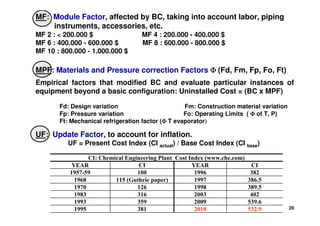
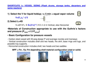
Cost Estimation Method of Guthrie
• Equipment purchase cost: Graphs and/or equations.
Based on a power law expression: Williams Law C = BC =Co (S/So)α
α
α
α 


 Economy of Scale (incremental cost C, decrease with larger capacities S)
Based on a polynomial expression BC = exp {A0 + A1 [ln (S)] + A2 [ln (S) ]2 +…}
• Installation: Module Factor, MF, affected by BC, taking into account
labor, piping instruments, accessories, etc.
Typical Value of MF=2.95 


 equipment cost is almost 3 times the BC.
Installation = (BC)(MF)-BC = BC(MF-1)
• For special materials, high pressures and special designs abroad base
capacities and costs (Co, So), the Materials and Pressure correction
Factors, MPF, are defined.
Uninstalled Cost = (BC)(MPF) Total Installed Cost = BC (MPF+MF-1)
• To update cost from mid-1968, an Update Factor, UF to account for
inflation is apply.
UF: Present Cost Index/Base Cost index
Updated bare module cost: BMC = UF(BC) (MPF+MF-1)
6
EQUIPMENT MPF
Pressure Vessels Fm . Fp
Heat Exchangers Fm (Fp + Fd)
Furnaces, direct fired heaters, Tray stacks Fm + Fp + Fd
Centrifugal pumps Fm . Fo
Compressors Fd
Materials and Pressure correction Factors: MPF
Empirical factors that modified BC and evaluate particular instances of
equipment beyond a basic configuration: Uninstalled Cost = (BC x MPF)
MPF = Φ
Φ
Φ
Φ (Fd, Fm, Fp, Fo, Ft)
Fd: Design variation Fm: Construction material variation
Fp: Pressure variation Fo: Operating Limits ( Φ
Φ
Φ
Φ of T, P)
Ft: Mechanical refrigeration factor Φ (
Φ (
Φ (
Φ (T evaporator)
)
)
)
Equipment Sizing Procedures
Need C and MPF 


 required the flowsheet mass and energy balance
(Flow, T, P, Q)
7
Equipment
purchase price
Pressure
Factor
Fp
Factor Base
Modular
Material Factor
Fm
Design Factor
Fd
UF
Total Cost =
Cp
Fbm
An example of Cost Estimation
8
Short-cut calculations
for the main
equipment sizing
Q, P
maintenance
∆
∆
∆
∆ Heat
contents
∆
∆
∆
∆
Composition
Q, P
streams
setting
2.- EQUIPMENT SIZING PROCEDURES
Vessels
Heat transfer equipment: Heat exchangers
Furnaces and Direct Fired Heaters
Refrigeration
Reactors
Columns, distillation and Absorption
Pumps, Compressors and Turbines
V
HX1
5
D1
P1 C1
C1
CT
H1IN
9
SHORTCUTS for VESSEL SIZING (Flash drums, storage tanks, decanters and
some reactors)
•Materials of Construction appropriate to use with the Guthrie´s factors
and pressure (Prated =1.5 Pactual)
• Basic Configuration for pressure vessels
- Carbon steel vessel with 50 psig design P and average nozzles and manways
- Vertical construction includes shell and two heads, the skirt, base rings and lugs, and
possible tray supports.
- Horizontal construction includes shell, two heads and two saddles
MPF = Fm . Fp; Fm depending shell material configuration (clad or solid)
V
V2
1) Select the V for liquid holdup; τ
τ
τ
τ= 5 min + equal vapor volume
V=(FL/ρ
ρ
ρ
ρL* τ
τ
τ
τ)*2
2) Select L=4D
V=πD2/4*L  D=(V/π
π
π
π)1/3; If D ≤1.2 m Vertical, else Horizontal
V
F
FL
FV
10
High Temperature Service
Tmax (oF) Steel
950 Carbon steel (CS)
1150 502 stainless steels (SS)
1300 410 SS; 330 SS
1500 304,321,347,316 SS.
Hastelloy C, X Inconel
2000 446 SS, Cast stainless, HC
Low Temperature Service
Tmin (oF) Steel
-50 Carbon steel (CS)
-75 Nickel steel (A203)
-320 Nickel steel (A353)
-425 302,304,310,347 (SS)
Materials of Construction for Pressure Vessels
Guthrie Material and pressure factors for pressure vessels: MPF = Fm Fp
Shell Material Clad, Fm Solid, Fm
Carbon Steel (CS) 1.00 1.00
Stainless 316 (SS) 2.25 3.67
Monel (Ni:Cr/2:1 alloy) 3.89 6.34
Titanium 4.23 7.89
Vessel Pressure (psig)
Up to 50 100 200 300 400 500 900 1000
Fp 1.00 1.05 1.15 1.20 1.35 1.45 2.30 2.50
11
SHORT CUT for REACTORS SIZING
5
1
R
R2
First step of the preliminary design  Not kinetic model available.
Mass Balance based on Product distribution  High influence in final cost
Assumptions: Reactor equivalent to laboratory reactor, adiabatic reactors
are isotherm at average T.
Assume space velocity (S in h-1)
S = (1/τ
τ
τ
τ) = µ /ρ
µ /ρ
µ /ρ
µ /ρ Vcat ; V = Vcat / 1- ε
ε
ε
ε
µ = Flow rate; ρ= molar density; Vcat= Volume of catalyst; ε= Void fraction of catalyst (e.g. ε=0.5)
12
HEAT TRANSFER EQUIPMENT SIZING
Heat exchanger types used in chemical process
By function
- Refrigerants (air or water) - Condensers (v, v+l  l) - Reboilers, vaporizers (lv) - Exchangers in general
By constructive shape
- Double pipe exchanger: the simplest one - Shell and tube exchangers: used for all applications
- Plate and frame exchangers - Air cooled: used for coolers and condensers
- Direct contact: used for cooling and quenching - Jacketed vessels, agitated vessels and internal coils
- Fired heaters: Furnaces and boilers
Shell and tube countercurrent exchanger, steady state
Q = U A ∆
∆
∆
∆Tlm
Q: From the energy balance
U: Estimation of heat transfer coefficient. Depending on configuration and media used
in the Shell and Tube side: L-L, Condensing vapor-L, Gas-L, Vaporizers). (Perry's
Handbook, 2008; www.tema.org).
A: Area
∆Tlm: Logarithmic Mean ∆T = (T1-t2)-(T2-t1)/ln (T1-t2/T2-t1)
- If phase changes  Approximation of 2 heat exchangers (A=A1+A2)
- Maximum area A ≤ 1000 m2, else  Parallel HX
MPF: Fm (Fp + Fd)
H1
EX1
H11
C1
C11
t1
t2
T1 T2
13
Heat exchanger: Countercurrent, steady state HX1
Guthrie Material and pressure factors for Heat Exchangers: MPF: Fm (Fp + Fd)
Design Type Fd Vessel Pressure (psig)
Kettle Reboiler 1.35
Floating Head 1.00 Up to 150 300 400 800 1000
U Tube 0.85 Fp 0.00 0.10 0.25 0.52 0.55
Fixed tube sheet 0.80
Shell/Tube Materials, Fm
Surface Area (ft2) CS/ CS/ CS/ SS/ CS/ Monel CS/ Ti/
CS Brass SS SS Monel Monel Ti Ti
Up to 100 1.00 1.05 1.54 2.50 2.00 3.20 4.10 10.28
100 to 500 1.00 1.10 1.78 3.10 2.30 3.50 5.20 10.60
500 to 1000 1.00 1.15 2.25 3.26 2.50 3.65 6.15 10.75
1000 to 5000 1.00 1.30 2.81 3.75 3.10 4.25 8.95 13.05
14
FURNACES and DIRECT FIRED HEATERS (boilers,reboilers, pyrolysis, reformers)
Q = Absorbed duty from heat balance
• Radiant section (qr=37.6 kW/m2 heat flux) + Convection section (qc=12.5 kW/m2
heat flux). Equal heat transmission (kW)  Arad=0.5 x kW/qr; Aconv=0.5 x kW/qc
• Basic configuration for furnaces is given by a process heater with a box or A-
frame construction, carbon steel tubes, and a 500 psig design P. This includes
complete field erection.
• Direct fired heaters is given by a process heater with cylindrical construction,
carbon steel tubes, and a 500 psig design.
Guthrie MPF for Furnaces: MPF= Fm+Fp+Fd
Design Type Fd
Process Heater 1.00
Pyrolisis 1.10
Reformer 1.35
Vessel Pressure (psig)
Up to 500 1000 1500 2000 2500 3000
Fp 0.00 0.10 0.15 0.25 0.40 0.60
Radiant Tube Material, Fm
Carbon Steel 0.00
Chrome/Moly 0.35
Stainless Steel 0.75
Guthrie MPF for Direct Fired Heaters
MPF: Fm + Fp + Fd
Design Type Fd
Cylindrical 1.00
Dowtherm 1.33
Vessel Pressure (psig)
Up to 500 1000 1500
Fp 0.00 0.15 0.20
Radiant Tube Material, Fm
Carbon Steel 0.00
Chrome/Moly 0.45
Stainless Steel 0.50
15
HEAT EXCHANGERS
16
SHORT CUT for DISTILLATION COLUMS SIZING
Gilliland used an empirical correlation to
calculate the final number of stage N from
the values calculated through the Fenske
and Underwood equations (Nmin, R, Rmin).
The procedure use a diagram; one enters
with the abscissa value known, and read
the ordinate of the corresponding point on
the Gilliland curve. The only unknown of
the ordinate is the number of stage N.
Rmin is given by Underwood with two equations that must be solved, where q is
the liquid fraction in the feed..
Fenske's equation applies to any two components lk and hk at infinite reflux and is
defined by Nmin, where αij is the geometric mean of the α's at the T of the feed,
distillate and the bottoms.
(
(
(
( )
)
)
)
(
(
(
( )
)
)
) 3
/
1
/
/
/
/
/
min
log
/
/
log
hk
lk
B
hk
lk
F
hk
lk
D
hk
lk
hk
lk
Bhk
Dhk
Blk
Dlk
x
x
x
x
N α
α
α
α
α
=
=
=
=
































=
=
=
=
17
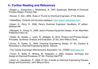
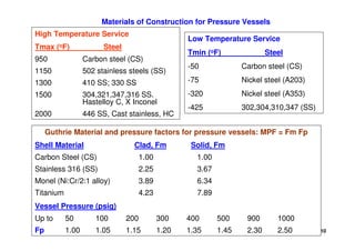
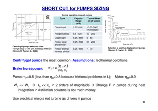
Simple and direct correlation for (nearly) ideal systems (Westerberg, 1978)
• Determine αlk/hk; βlk = ξlk; βhk = 1- ξhk
• Calculate tray number Ni and reflux ratio Ri from correlations (i= lk, hk):
Ni = 12.3 / (αlk/hk-1)2/3 . (1- βi)1/6 Ri = 1.38 / (αlk/hk-1)0.9 . (1- βi)0.1
- Theoretical nº of trays NT = 0.8 max[Ni] + 0.2 min[Ni]; R= 0.8 max[Ri] + 0.2 min[Ri]
- Actual nº of trays N = NT/0.8
- For H consider 0.6 m spacing (H=0.6 N); Maximum H=60 m  else, 2 columns
* Calculate column diameter, D, by internal flowrates and taking into account
the vapor fraction of F. Internal flowrates used to sizing condenser, reboiler
Design column at 80% of linear flooding velocity
If D 3m  Parallel columns
* Calculate heat duties for reboiler and condenser
* Costing vessel and stack trays (24” spacing)
SHORT CUT for DISTILLATION COLUMS SIZING
2
.
0
5
.
0
20











 −
=
σ
ρ
ρ
ρ
G
G
L
sb
f C
U
k
vap
reb H
V
Q ∆
=








=
=
G
f
U
V
D
A
ρ
ε
π
8
.
0
4
2
( ) k
vap
n
k
dk
k
vap
n
k
k
L
k
D
L
V
cond H
D
V
H
H
H
Q ∆
=
∆
+
=
−
= ∑
∑ =
= 1
1
µ
µ
µ
18
DISTILLATION COLUMNS
D1
D2
Guthrie MPF for Tray
Stacks
MPF: Fm + Fs + Ft
Tray Type Ft
Grid 0.0
Plate 0.0
Sieve 0.0
Valve o trough 0.4
Bubble Cap 1.8
Koch Kascade 3.9
Tray Spacing, Fs
(inch) 24” 18” 12”
Fs 1.0 1.4 2.2
Tray Material, Fm
Carbon Steel 0.0
Stainless Steel 1.7
Monel 8.9
19
DISTILLATION COLUMNS
20
SHORT CUT for ABSORBERS COLUMS SIZING
Sizing similar to the distillation columns
NT  Kremser equation
• Assumption: v-l equilibrium  but actually there is mass transfer phenomena (e.g.
simulation of CO2- MEA absorption)  20% efficiency in nº trays  N = NT/0.2
• Calculate H and D for costing vessel and stack trays (24” spacing)
E1
)
ln(
/
)
1
(
)
(
ln
1
0
1
0 n
E
n
N
n
n
E
n
n
N
n
E
n
n
A
v
r
A
l
v
A
r
l
N 





−
−
−
+
=
+
+
21
SHORT CUT for COMPRESSORS (or TURBINES) SIZING
Centrifugal compressors are the most common compressors (High capacities, low
compression ratios –r-) vs. Reciprocating compressors (Low capacities, high r)
Assumptions: Ideal behavior, isentropic and adiabatic
Drivers
1) Electric motors driving compressor; ηM=0.9; ηC=0.8 (compressor)
Brake horsepower Wb= W/ηM ηC= 1.39 W
2) Turbine diving compressor (e.g.IGCC where need decrease P); ηT=0.8; Wb=1.562 W
Max. Horsepower compressor = 10.000 hp = 7.5 MW
Max Compression ratio r = P2/P1  5.
Staged compressors  to decrease work using intercoolers in N stages
Work is minimised when compression ratios are the same
P1/P0 = P2/P1 = …. = PN/PN-1 = (PN/P0 )1/N
Rule of thumb  (PN/P0)1/N = 2.5  N










−
















−
=
−
1
1
1
0
0
γ
γ
γ
γ
µ
N
N
P
P
T
R
N
W
C1
P1, T1 P2, T2
P2  P1
T2  T1
W
µ
Compressor
P1, T1 P2, T2
P2  P1
T2  T1
W
µ
Turbine
C1
C1 C1 C1 C1
P0
T0
P1
Ta
P1
T0
P2
Ta
P2
T0
P3
Ta
PN-1
T0
PN
Ta
CT
H1IN CT
H1IN CT
H1IN
22
STEAM TURBINE SH-25 GAS TURBINE
COMPRESSORS
23
SHORT CUT for PUMPS SIZING
Centrifugal pumps the most common. Assumptions: Isothermal conditions
Brake horsepower:
Pump: ηP=0.5 (less than ηC=0.8 because frictional problems in L); Motor: ηM=0.9
Wb  Wc  €b  €c in 2 orders of magnitude  Change P in pumps during heat
integration in distillation columns is not much money
Use electrical motors not turbine as drivers in pumps
P1
(
(
(
( )
)
)
)
M
P
b
P
P
W
η
η
ρ
µ 1
2 −
−
−
−
=
=
=
=
Centrifugal pumps selection guide.
(*)single-stage  1750 rpm, multi-stage 1750 rpm
(Sinnot, R, Towler, G., 2009)
Selection of positive displacement pumps
(Sinnot, R, Towler, G., 2009)
60 - 200
0.05 - 500
Rotary gear
and similar
5 - 60
0.05 - 500
Diaphragm
50 - 200
0.5 - 500
Reciprocating
10-50 3000
(multistage)
0.25 - 103
Centrifugal
Type Capacity
Range
(m3/h)
Typical Head
(m of water)
Rotary sliding
vane or similar
0.25 - 500 7 - 70
Normal operating range of pumps
24
PUMPS
SPECIFICATIONS
Pump Type: Centrifugal
Flow / P Specifications
Liquid Flow: 170.000 GPM
Discharge P: 43.0 psi
Inlet Size: 2.000 inch
Discharge Size: 1.500 inch
Media Temperature; 250 F
Power Specifications
Power Source AC;
100/200Single
Market Segment: General
use; Paper Industry
Pump Type: Centrifugal
Flow / P Specifications
Liquid Flow:1541.003 GPM
Discharge P: 507.6 psi
Media Temperature: 662 F
Power Specifications:
Power Source DC Market
Segment: General use;
Petrochemical or
Hydrocarbon; Chemical
Industry.
Pump Type: Centrifugal
Flow / P Specifications
Liquid Flow 15400.000 GPM
Discharge P: 212.0 psi
Inlet Size 16.000 inch
Discharge Size 16.000 inch
Media T: 572 F
Power Specifications:
Power Source AC; Electric
Motor
Market Segment General
use; Mining; Chemical
Industry
25
Guthrie MPF for Centrifugal
Pumps and Drivers
MPF: Fm.Fo
Material Type, Fm
Cast iron 1.00
Bronze 1.28
Stainless 1.93
Hastelloy C 2.89
Monel 3.23
Nickel 3.48
Titanium 8.98
Operating Limits, Fo
Max. Suction P (psig) 150 500 1000
Max. T (ºF) 250 550 850
Fo 1.0 1.5 2.9
Guthrie MPF for Compressors
MPF: Fd
Design Type, Fd
Centrifugal/motor 1.00
Reciprocating/steam 1.07
Centrifugal/turbine 1.15
Reciprocating/motor 1.29
Reciprocating/gas engine 1.82
Guthrie MPF for Mechanical
Refrigeration
MPF: Ft
Evaporator Temperature, Ft
278 K / 5 C 1.00
266 K / -7 C 1.95
255 K / -18 C 2.25
244 K / -29 C 3.95
233 K / -40 C 4.54
PUMPS
COMPRESSORS
REFRIGERATION
P1
C1
Guthrie Material and Pressure Factors for Centrifugal Pumps and Drivers,
Compressors and Mechanical Refrigeration.
26
SHORT CUT for REFRIGERATION SIZING
Short cut model (multiple stages)
Multiple stages for low T process stream
Refrigerant R must satisfy
a) Tcond  Tc
R max Tcond = 0.9 Tc (critcal component)
b) TevapTboil,R  Pevap=PR
0  1 atm. (To prevent decreasing η due to air in the system)
c) Tevap and Tcond must be feasible for heat exchange; ∆T ≈ 5K
More steps  Less energy vs. More capital investment (compressors)  Trade-off
Rule of Thumb: One cycle for 30 K below ambient Nº cycles = N = (300-Tcold)/30
Q
CP
Q
CP
Q
W
N
c
N






+
=








−






+
=
1
1
;
1
1
1
Condenser
Cooling
water
2
4
C1
3
Valve
Compressor
Evaporator
W’
Process stream
to be cooled
Tcold
1
2
3
4
Q’
Q’c
3 2
1
4
Q’c
Q’
W’
L
P
∆
∆
∆
∆H
V
Short cut model (one cycle/one stage)
1 cycle for process stream T not too low
Coefficient of performance (CP)
CP = Q/W, typically CP ≈ 4  Compressor W=Q/4
For h=0.9; hcomp=0.8  Wb = W/0.72; Cooling duty Qc= W+Q = 5/4 Q
27
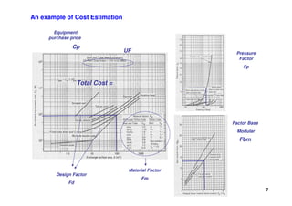
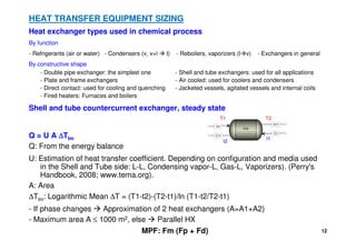
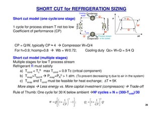
[Tables 4.11-4.12; p.134 (Biegler et al., 1997)  Table 22.32; p.591-595 (Seider et al., 2010)]
3.- COST ESTIMATION OF EQUIPMENT: Base Costs for equipment units
Base Costs for Pressure Vessels
Equipment Type C0 ($) L0(ft) D0(ft) α
α
α
α β
β
β
β MF2/MF4/MF6/MF8/MF10
Vertical fabrication 1000 4.0 3.0 0.81 1.05 4.23/4.12/4.07/4.06/4.02
1≤D ≤10 ft; 4 ≤ L ≤100 ft
Horizontal fabrication 690 4.0 3.0 0.78 0.98 3.18/3.06/3.01/2.99/2.96
1≤D ≤10 ft; 4 ≤ L ≤100 ft
Tray stacks 180 10.0 2.0 0.97 1.45 1.0/1.0/1.0/1.0/1.0
2≤D ≤10 ft; 1 ≤ L ≤500 ft
Base Costs for Process Equipment
Equipment Type C0 ($103) S0 Range (S) α
α
α
α MF2/MF4/MF6/MF8/MF10
Process furnaces 100 30 100-300 0.83 2.27/2.19/2.16/2.15/2.13
S=Absorbed duty (106Btu/h)
Direct fired heaters 20 5 1-40 0.77 2.23/2.15/2.13/2.12/2.10
S=Absorbed duty (106Btu/h)
Heat exchanger 5 400 100-104 0.65 3.29/3.18/3.14/3.12/3.09
Shell and tube, S=Area (ft2)
Heat exchanger 0.3 5.5 2-100 0.024 1.83/1.83/1.83/1.83/1.83
Shell and tube, S=Area (ft2)
Air Coolers 3 200 100-104 0.82 2.31/2.21/2.18/2.16/2.15
S=[calculated area (ft2)/15.5]
Centrifugal pumps 0.39 10 10-2.103 0.17 3.38/3.28/3.24/3.23/3.20
S= C/H factor (gpm x psi) 0.65 2.103 2.103 -2.104 0.36 3.38/3.28/3.24/3.23/3.20
1.5 2.104 2.104 -2.105 0.64 3.38/3.28/3.24/3.23/3.20
Compressors 23 100 30-104 0.77 3.11/3.01/2.97/2.96/2.93
S=brake horsepower
Refrigeration 60 200 50-3000 0.70 1.42
S=ton refrigeration (12,000 Btu/h removed)
28
BC
Guthrie´s modular method to preliminary design.
Updated Bare Module Cost = UF . BC . (MPF + MF -1)
Williams Law: C = BC =Co (S/So)α
α
α
α
Non-linear behaviour of Cost, C vs., Size, S  Economy of Scale (incremental
cost decrease with larger capacities
C = BC =Co (S/So)α
α
α
α log C = log (Co/So)α
α
α
α + α
α
α
α log S
Co, So. Parameters of Basic configuration Costs and Capacities
α.
α.
α.
α. Parameter  1  economy of scale
Base Cost for Pressure Vessels: Vertical, horizontal, tray stack
C =Co (L/Lo)a (D/Do)b
Base Cost for Process Equipment
C =Co (S/So)α
α
α
α ; Range of S
Tables
for
each
equipment
3.- COST ESTIMATION OF EQUIPMENT
29
CI: Chemical Engineering Plant Cost Index (www.che.com)
YEAR CI YEAR CI
1957-59 100 1996 382
1968 115 (Guthrie paper) 1997 386.5
1970 126 1998 389.5
1983 316 2003 402
1993 359 2009 539.6
1995 381 2010 532.9
MF: Module Factor, affected by BC, taking into account labor, piping
instruments, accessories, etc.
MF 2 :  200.000 $ MF 4 : 200.000 - 400.000 $
MF 6 : 400.000 - 600.000 $ MF 8 : 600.000 - 800.000 $
MF 10 : 800.000 - 1.000.000 $
MPF: Materials and Pressure correction Factors Φ
Φ
Φ
Φ (Fd, Fm, Fp, Fo, Ft)
Empirical factors that modified BC and evaluate particular instances of
equipment beyond a basic configuration: Uninstalled Cost = (BC x MPF)
Fd: Design variation Fm: Construction material variation
Fp: Pressure variation Fo: Operating Limits ( Φ
Φ
Φ
Φ of T, P)
Ft: Mechanical refrigeration factor (Φ
Φ
Φ
Φ T evaporator)
)
)
)
UF: Update Factor, to account for inflation.
UF = Present Cost Index (CI actual) / Base Cost Index (CI base)
30
4.- Further Reading and References
• Biegler, L., Grossmann, I., Westerberg , A., 1997, Systematic Methods of Chemical
Process Design, Prentice Hall.
• Branan, C. (Ed.), 2005, Rules of Thumb for Chemical Engineers, 4th Ed. Elsevier.
• GlobalSpec. Products and services catalogue. http://search.globalspec.com.
• Green, D., Perry, R., 2008, Perry's Chemical Engineers' Handbook. 8th edition.
McGraw-Hill.
• Mahajani, V., Umarji, S., 2009, Joshi's Process Equipment Design. 4th ed. Macmillan
Publishers India Ltd.
• Seider, W., Seader, J., Lewin, D., Widagdo, S., 2010, Product and Process Design
Principles. Synthesis, Analysis and Evaluation. 3rd Ed. John Wiley  Sons.
• Sinnot, R, Towler, G., 2009, Chemical Engineering Design. 5th Ed. Coulson 
Richardson´s Chemical Engineering Series. Elsevier.
• The Tubular Exchanger Manufacturers Association, Inc. (TEMA) www.tema.org.
• Turton, R., Bailie, R., Whiting, W., Shaeiwitz, J., 2003, Analysis, Synthesis and
Design of Chemical Processes, 2nd Ed. Prentice Hall PTR.
• Ulrich, G., Vasudevan, P., 2004, 2nd Ed. A Guide to Chemical Engineering Process
Design and Economics. John Wiley  Sons.

Equipment Sizing.pdf

  • 1.
    Subject 7. EquipmentSizing and Cos8ng Chemical Process Design Javier R. Viguri Fuente CHEMICAL ENGINEERING AND INORGANIC CHEMISTRY DEPARTMENT UNIVERSITY OF CANTABRIA javier.viguri@unican.es License: Crea8ve Commons BY‐NC‐SA 3.0
  • 2.
    2 INDEX 1.- Introduction • Categoriesof total capital cost estimates • Cost estimation method of Guthrie 2.- Short cuts for equipment sizing procedures • Vessel (flash drums, storage tanks, decanters and some reactors) • Reactors • Heat transfer equipment (heat exchangers, furnaces and direct fired heaters) • Distillation columns • Absorbers columns • Compressors (or turbines) • Pumps • Refrigeration 3.- Cost estimation of equipment • Base costs for equipment units • Guthrie´s modular method 4.- Further Reading and References
  • 3.
    3 1.- INTRODUCTION Process AlternativesSynthesis (candidate flowsheet) Analysis (Preliminary mass and energy balances) SIZING (Sizes and capacities) COST ESTIMATION (Capital and operation) Economic Analysis (economic criteria) SIZING Calculation of all physical attributes that allow a unique costing of this unit - Capacity, Height - Pressure rating -Cross sectional area – Materials of construction Short-cut, approximate calculations (correlations) Quick obtaining of sizing parameters Order of magnitude estimated parameters COST Total Capital Investment or Capital Cost: Function of the process equipment The sized equipment will be costed * Approximate methods to estimate costs Manufacturing Cost: Function of process equipment and utility charges
  • 4.
    4 Categories of totalcapital cost estimates based on accuracy of the estimate ESTIMATE BASED ON Error (%) Obtention USED TO ORDER OF MAGNITUDE (Ratio estimate) Method of Hill, 1956. Production rate and PFD with compressors, reactors and separation equipments. Based on similar plants. 40 - 50 Very fast Profitability analysis STUDY Overall Factor Method of Lang, 1947. Mass energy balance and equipment sizing. 25 - 40 Fast Preliminary design PRELIMINARY Individual Factors Method of Guthrie, 1969, 1974. Mass energy balance, equipment sizing, construction materials and PID. Enough data to budget estimation. 15 - 25 Medium Budget approval DEFINITIVE Full data but before drawings and specifications. 10 -15 Slow Construction control DETAILED Detailed Engineering 5 -10 Very slow Turnkey contract
  • 5.
    5 Cost Estimation Methodof Guthrie • Equipment purchase cost: Graphs and/or equations. Based on a power law expression: Williams Law C = BC =Co (S/So)α α α α Economy of Scale (incremental cost C, decrease with larger capacities S) Based on a polynomial expression BC = exp {A0 + A1 [ln (S)] + A2 [ln (S) ]2 +…} • Installation: Module Factor, MF, affected by BC, taking into account labor, piping instruments, accessories, etc. Typical Value of MF=2.95 equipment cost is almost 3 times the BC. Installation = (BC)(MF)-BC = BC(MF-1) • For special materials, high pressures and special designs abroad base capacities and costs (Co, So), the Materials and Pressure correction Factors, MPF, are defined. Uninstalled Cost = (BC)(MPF) Total Installed Cost = BC (MPF+MF-1) • To update cost from mid-1968, an Update Factor, UF to account for inflation is apply. UF: Present Cost Index/Base Cost index Updated bare module cost: BMC = UF(BC) (MPF+MF-1)
  • 6.
    6 EQUIPMENT MPF Pressure VesselsFm . Fp Heat Exchangers Fm (Fp + Fd) Furnaces, direct fired heaters, Tray stacks Fm + Fp + Fd Centrifugal pumps Fm . Fo Compressors Fd Materials and Pressure correction Factors: MPF Empirical factors that modified BC and evaluate particular instances of equipment beyond a basic configuration: Uninstalled Cost = (BC x MPF) MPF = Φ Φ Φ Φ (Fd, Fm, Fp, Fo, Ft) Fd: Design variation Fm: Construction material variation Fp: Pressure variation Fo: Operating Limits ( Φ Φ Φ Φ of T, P) Ft: Mechanical refrigeration factor Φ ( Φ ( Φ ( Φ (T evaporator) ) ) ) Equipment Sizing Procedures Need C and MPF required the flowsheet mass and energy balance (Flow, T, P, Q)
  • 7.
    7 Equipment purchase price Pressure Factor Fp Factor Base Modular MaterialFactor Fm Design Factor Fd UF Total Cost = Cp Fbm An example of Cost Estimation
  • 8.
    8 Short-cut calculations for themain equipment sizing Q, P maintenance ∆ ∆ ∆ ∆ Heat contents ∆ ∆ ∆ ∆ Composition Q, P streams setting 2.- EQUIPMENT SIZING PROCEDURES Vessels Heat transfer equipment: Heat exchangers Furnaces and Direct Fired Heaters Refrigeration Reactors Columns, distillation and Absorption Pumps, Compressors and Turbines V HX1 5 D1 P1 C1 C1 CT H1IN
  • 9.
    9 SHORTCUTS for VESSELSIZING (Flash drums, storage tanks, decanters and some reactors) •Materials of Construction appropriate to use with the Guthrie´s factors and pressure (Prated =1.5 Pactual) • Basic Configuration for pressure vessels - Carbon steel vessel with 50 psig design P and average nozzles and manways - Vertical construction includes shell and two heads, the skirt, base rings and lugs, and possible tray supports. - Horizontal construction includes shell, two heads and two saddles MPF = Fm . Fp; Fm depending shell material configuration (clad or solid) V V2 1) Select the V for liquid holdup; τ τ τ τ= 5 min + equal vapor volume V=(FL/ρ ρ ρ ρL* τ τ τ τ)*2 2) Select L=4D V=πD2/4*L D=(V/π π π π)1/3; If D ≤1.2 m Vertical, else Horizontal V F FL FV
  • 10.
    10 High Temperature Service Tmax(oF) Steel 950 Carbon steel (CS) 1150 502 stainless steels (SS) 1300 410 SS; 330 SS 1500 304,321,347,316 SS. Hastelloy C, X Inconel 2000 446 SS, Cast stainless, HC Low Temperature Service Tmin (oF) Steel -50 Carbon steel (CS) -75 Nickel steel (A203) -320 Nickel steel (A353) -425 302,304,310,347 (SS) Materials of Construction for Pressure Vessels Guthrie Material and pressure factors for pressure vessels: MPF = Fm Fp Shell Material Clad, Fm Solid, Fm Carbon Steel (CS) 1.00 1.00 Stainless 316 (SS) 2.25 3.67 Monel (Ni:Cr/2:1 alloy) 3.89 6.34 Titanium 4.23 7.89 Vessel Pressure (psig) Up to 50 100 200 300 400 500 900 1000 Fp 1.00 1.05 1.15 1.20 1.35 1.45 2.30 2.50
  • 11.
    11 SHORT CUT forREACTORS SIZING 5 1 R R2 First step of the preliminary design Not kinetic model available. Mass Balance based on Product distribution High influence in final cost Assumptions: Reactor equivalent to laboratory reactor, adiabatic reactors are isotherm at average T. Assume space velocity (S in h-1) S = (1/τ τ τ τ) = µ /ρ µ /ρ µ /ρ µ /ρ Vcat ; V = Vcat / 1- ε ε ε ε µ = Flow rate; ρ= molar density; Vcat= Volume of catalyst; ε= Void fraction of catalyst (e.g. ε=0.5)
  • 12.
    12 HEAT TRANSFER EQUIPMENTSIZING Heat exchanger types used in chemical process By function - Refrigerants (air or water) - Condensers (v, v+l l) - Reboilers, vaporizers (lv) - Exchangers in general By constructive shape - Double pipe exchanger: the simplest one - Shell and tube exchangers: used for all applications - Plate and frame exchangers - Air cooled: used for coolers and condensers - Direct contact: used for cooling and quenching - Jacketed vessels, agitated vessels and internal coils - Fired heaters: Furnaces and boilers Shell and tube countercurrent exchanger, steady state Q = U A ∆ ∆ ∆ ∆Tlm Q: From the energy balance U: Estimation of heat transfer coefficient. Depending on configuration and media used in the Shell and Tube side: L-L, Condensing vapor-L, Gas-L, Vaporizers). (Perry's Handbook, 2008; www.tema.org). A: Area ∆Tlm: Logarithmic Mean ∆T = (T1-t2)-(T2-t1)/ln (T1-t2/T2-t1) - If phase changes Approximation of 2 heat exchangers (A=A1+A2) - Maximum area A ≤ 1000 m2, else Parallel HX MPF: Fm (Fp + Fd) H1 EX1 H11 C1 C11 t1 t2 T1 T2
  • 13.
    13 Heat exchanger: Countercurrent,steady state HX1 Guthrie Material and pressure factors for Heat Exchangers: MPF: Fm (Fp + Fd) Design Type Fd Vessel Pressure (psig) Kettle Reboiler 1.35 Floating Head 1.00 Up to 150 300 400 800 1000 U Tube 0.85 Fp 0.00 0.10 0.25 0.52 0.55 Fixed tube sheet 0.80 Shell/Tube Materials, Fm Surface Area (ft2) CS/ CS/ CS/ SS/ CS/ Monel CS/ Ti/ CS Brass SS SS Monel Monel Ti Ti Up to 100 1.00 1.05 1.54 2.50 2.00 3.20 4.10 10.28 100 to 500 1.00 1.10 1.78 3.10 2.30 3.50 5.20 10.60 500 to 1000 1.00 1.15 2.25 3.26 2.50 3.65 6.15 10.75 1000 to 5000 1.00 1.30 2.81 3.75 3.10 4.25 8.95 13.05
  • 14.
    14 FURNACES and DIRECTFIRED HEATERS (boilers,reboilers, pyrolysis, reformers) Q = Absorbed duty from heat balance • Radiant section (qr=37.6 kW/m2 heat flux) + Convection section (qc=12.5 kW/m2 heat flux). Equal heat transmission (kW) Arad=0.5 x kW/qr; Aconv=0.5 x kW/qc • Basic configuration for furnaces is given by a process heater with a box or A- frame construction, carbon steel tubes, and a 500 psig design P. This includes complete field erection. • Direct fired heaters is given by a process heater with cylindrical construction, carbon steel tubes, and a 500 psig design. Guthrie MPF for Furnaces: MPF= Fm+Fp+Fd Design Type Fd Process Heater 1.00 Pyrolisis 1.10 Reformer 1.35 Vessel Pressure (psig) Up to 500 1000 1500 2000 2500 3000 Fp 0.00 0.10 0.15 0.25 0.40 0.60 Radiant Tube Material, Fm Carbon Steel 0.00 Chrome/Moly 0.35 Stainless Steel 0.75 Guthrie MPF for Direct Fired Heaters MPF: Fm + Fp + Fd Design Type Fd Cylindrical 1.00 Dowtherm 1.33 Vessel Pressure (psig) Up to 500 1000 1500 Fp 0.00 0.15 0.20 Radiant Tube Material, Fm Carbon Steel 0.00 Chrome/Moly 0.45 Stainless Steel 0.50
  • 15.
  • 16.
    16 SHORT CUT forDISTILLATION COLUMS SIZING Gilliland used an empirical correlation to calculate the final number of stage N from the values calculated through the Fenske and Underwood equations (Nmin, R, Rmin). The procedure use a diagram; one enters with the abscissa value known, and read the ordinate of the corresponding point on the Gilliland curve. The only unknown of the ordinate is the number of stage N. Rmin is given by Underwood with two equations that must be solved, where q is the liquid fraction in the feed.. Fenske's equation applies to any two components lk and hk at infinite reflux and is defined by Nmin, where αij is the geometric mean of the α's at the T of the feed, distillate and the bottoms. ( ( ( ( ) ) ) ) ( ( ( ( ) ) ) ) 3 / 1 / / / / / min log / / log hk lk B hk lk F hk lk D hk lk hk lk Bhk Dhk Blk Dlk x x x x N α α α α α = = = =                                 = = = =
  • 17.
    17 Simple and directcorrelation for (nearly) ideal systems (Westerberg, 1978) • Determine αlk/hk; βlk = ξlk; βhk = 1- ξhk • Calculate tray number Ni and reflux ratio Ri from correlations (i= lk, hk): Ni = 12.3 / (αlk/hk-1)2/3 . (1- βi)1/6 Ri = 1.38 / (αlk/hk-1)0.9 . (1- βi)0.1 - Theoretical nº of trays NT = 0.8 max[Ni] + 0.2 min[Ni]; R= 0.8 max[Ri] + 0.2 min[Ri] - Actual nº of trays N = NT/0.8 - For H consider 0.6 m spacing (H=0.6 N); Maximum H=60 m else, 2 columns * Calculate column diameter, D, by internal flowrates and taking into account the vapor fraction of F. Internal flowrates used to sizing condenser, reboiler Design column at 80% of linear flooding velocity If D 3m Parallel columns * Calculate heat duties for reboiler and condenser * Costing vessel and stack trays (24” spacing) SHORT CUT for DISTILLATION COLUMS SIZING 2 . 0 5 . 0 20             − = σ ρ ρ ρ G G L sb f C U k vap reb H V Q ∆ =         = = G f U V D A ρ ε π 8 . 0 4 2 ( ) k vap n k dk k vap n k k L k D L V cond H D V H H H Q ∆ = ∆ + = − = ∑ ∑ = = 1 1 µ µ µ
  • 18.
    18 DISTILLATION COLUMNS D1 D2 Guthrie MPFfor Tray Stacks MPF: Fm + Fs + Ft Tray Type Ft Grid 0.0 Plate 0.0 Sieve 0.0 Valve o trough 0.4 Bubble Cap 1.8 Koch Kascade 3.9 Tray Spacing, Fs (inch) 24” 18” 12” Fs 1.0 1.4 2.2 Tray Material, Fm Carbon Steel 0.0 Stainless Steel 1.7 Monel 8.9
  • 19.
  • 20.
    20 SHORT CUT forABSORBERS COLUMS SIZING Sizing similar to the distillation columns NT Kremser equation • Assumption: v-l equilibrium but actually there is mass transfer phenomena (e.g. simulation of CO2- MEA absorption) 20% efficiency in nº trays N = NT/0.2 • Calculate H and D for costing vessel and stack trays (24” spacing) E1 ) ln( / ) 1 ( ) ( ln 1 0 1 0 n E n N n n E n n N n E n n A v r A l v A r l N       − − − + = + +
  • 21.
    21 SHORT CUT forCOMPRESSORS (or TURBINES) SIZING Centrifugal compressors are the most common compressors (High capacities, low compression ratios –r-) vs. Reciprocating compressors (Low capacities, high r) Assumptions: Ideal behavior, isentropic and adiabatic Drivers 1) Electric motors driving compressor; ηM=0.9; ηC=0.8 (compressor) Brake horsepower Wb= W/ηM ηC= 1.39 W 2) Turbine diving compressor (e.g.IGCC where need decrease P); ηT=0.8; Wb=1.562 W Max. Horsepower compressor = 10.000 hp = 7.5 MW Max Compression ratio r = P2/P1 5. Staged compressors to decrease work using intercoolers in N stages Work is minimised when compression ratios are the same P1/P0 = P2/P1 = …. = PN/PN-1 = (PN/P0 )1/N Rule of thumb (PN/P0)1/N = 2.5 N           −                 − = − 1 1 1 0 0 γ γ γ γ µ N N P P T R N W C1 P1, T1 P2, T2 P2 P1 T2 T1 W µ Compressor P1, T1 P2, T2 P2 P1 T2 T1 W µ Turbine C1 C1 C1 C1 C1 P0 T0 P1 Ta P1 T0 P2 Ta P2 T0 P3 Ta PN-1 T0 PN Ta CT H1IN CT H1IN CT H1IN
  • 22.
    22 STEAM TURBINE SH-25GAS TURBINE COMPRESSORS
  • 23.
    23 SHORT CUT forPUMPS SIZING Centrifugal pumps the most common. Assumptions: Isothermal conditions Brake horsepower: Pump: ηP=0.5 (less than ηC=0.8 because frictional problems in L); Motor: ηM=0.9 Wb Wc €b €c in 2 orders of magnitude Change P in pumps during heat integration in distillation columns is not much money Use electrical motors not turbine as drivers in pumps P1 ( ( ( ( ) ) ) ) M P b P P W η η ρ µ 1 2 − − − − = = = = Centrifugal pumps selection guide. (*)single-stage 1750 rpm, multi-stage 1750 rpm (Sinnot, R, Towler, G., 2009) Selection of positive displacement pumps (Sinnot, R, Towler, G., 2009) 60 - 200 0.05 - 500 Rotary gear and similar 5 - 60 0.05 - 500 Diaphragm 50 - 200 0.5 - 500 Reciprocating 10-50 3000 (multistage) 0.25 - 103 Centrifugal Type Capacity Range (m3/h) Typical Head (m of water) Rotary sliding vane or similar 0.25 - 500 7 - 70 Normal operating range of pumps
  • 24.
    24 PUMPS SPECIFICATIONS Pump Type: Centrifugal Flow/ P Specifications Liquid Flow: 170.000 GPM Discharge P: 43.0 psi Inlet Size: 2.000 inch Discharge Size: 1.500 inch Media Temperature; 250 F Power Specifications Power Source AC; 100/200Single Market Segment: General use; Paper Industry Pump Type: Centrifugal Flow / P Specifications Liquid Flow:1541.003 GPM Discharge P: 507.6 psi Media Temperature: 662 F Power Specifications: Power Source DC Market Segment: General use; Petrochemical or Hydrocarbon; Chemical Industry. Pump Type: Centrifugal Flow / P Specifications Liquid Flow 15400.000 GPM Discharge P: 212.0 psi Inlet Size 16.000 inch Discharge Size 16.000 inch Media T: 572 F Power Specifications: Power Source AC; Electric Motor Market Segment General use; Mining; Chemical Industry
  • 25.
    25 Guthrie MPF forCentrifugal Pumps and Drivers MPF: Fm.Fo Material Type, Fm Cast iron 1.00 Bronze 1.28 Stainless 1.93 Hastelloy C 2.89 Monel 3.23 Nickel 3.48 Titanium 8.98 Operating Limits, Fo Max. Suction P (psig) 150 500 1000 Max. T (ºF) 250 550 850 Fo 1.0 1.5 2.9 Guthrie MPF for Compressors MPF: Fd Design Type, Fd Centrifugal/motor 1.00 Reciprocating/steam 1.07 Centrifugal/turbine 1.15 Reciprocating/motor 1.29 Reciprocating/gas engine 1.82 Guthrie MPF for Mechanical Refrigeration MPF: Ft Evaporator Temperature, Ft 278 K / 5 C 1.00 266 K / -7 C 1.95 255 K / -18 C 2.25 244 K / -29 C 3.95 233 K / -40 C 4.54 PUMPS COMPRESSORS REFRIGERATION P1 C1 Guthrie Material and Pressure Factors for Centrifugal Pumps and Drivers, Compressors and Mechanical Refrigeration.
  • 26.
    26 SHORT CUT forREFRIGERATION SIZING Short cut model (multiple stages) Multiple stages for low T process stream Refrigerant R must satisfy a) Tcond Tc R max Tcond = 0.9 Tc (critcal component) b) TevapTboil,R Pevap=PR 0 1 atm. (To prevent decreasing η due to air in the system) c) Tevap and Tcond must be feasible for heat exchange; ∆T ≈ 5K More steps Less energy vs. More capital investment (compressors) Trade-off Rule of Thumb: One cycle for 30 K below ambient Nº cycles = N = (300-Tcold)/30 Q CP Q CP Q W N c N       + =         −       + = 1 1 ; 1 1 1 Condenser Cooling water 2 4 C1 3 Valve Compressor Evaporator W’ Process stream to be cooled Tcold 1 2 3 4 Q’ Q’c 3 2 1 4 Q’c Q’ W’ L P ∆ ∆ ∆ ∆H V Short cut model (one cycle/one stage) 1 cycle for process stream T not too low Coefficient of performance (CP) CP = Q/W, typically CP ≈ 4 Compressor W=Q/4 For h=0.9; hcomp=0.8 Wb = W/0.72; Cooling duty Qc= W+Q = 5/4 Q
  • 27.
    27 [Tables 4.11-4.12; p.134(Biegler et al., 1997) Table 22.32; p.591-595 (Seider et al., 2010)] 3.- COST ESTIMATION OF EQUIPMENT: Base Costs for equipment units Base Costs for Pressure Vessels Equipment Type C0 ($) L0(ft) D0(ft) α α α α β β β β MF2/MF4/MF6/MF8/MF10 Vertical fabrication 1000 4.0 3.0 0.81 1.05 4.23/4.12/4.07/4.06/4.02 1≤D ≤10 ft; 4 ≤ L ≤100 ft Horizontal fabrication 690 4.0 3.0 0.78 0.98 3.18/3.06/3.01/2.99/2.96 1≤D ≤10 ft; 4 ≤ L ≤100 ft Tray stacks 180 10.0 2.0 0.97 1.45 1.0/1.0/1.0/1.0/1.0 2≤D ≤10 ft; 1 ≤ L ≤500 ft Base Costs for Process Equipment Equipment Type C0 ($103) S0 Range (S) α α α α MF2/MF4/MF6/MF8/MF10 Process furnaces 100 30 100-300 0.83 2.27/2.19/2.16/2.15/2.13 S=Absorbed duty (106Btu/h) Direct fired heaters 20 5 1-40 0.77 2.23/2.15/2.13/2.12/2.10 S=Absorbed duty (106Btu/h) Heat exchanger 5 400 100-104 0.65 3.29/3.18/3.14/3.12/3.09 Shell and tube, S=Area (ft2) Heat exchanger 0.3 5.5 2-100 0.024 1.83/1.83/1.83/1.83/1.83 Shell and tube, S=Area (ft2) Air Coolers 3 200 100-104 0.82 2.31/2.21/2.18/2.16/2.15 S=[calculated area (ft2)/15.5] Centrifugal pumps 0.39 10 10-2.103 0.17 3.38/3.28/3.24/3.23/3.20 S= C/H factor (gpm x psi) 0.65 2.103 2.103 -2.104 0.36 3.38/3.28/3.24/3.23/3.20 1.5 2.104 2.104 -2.105 0.64 3.38/3.28/3.24/3.23/3.20 Compressors 23 100 30-104 0.77 3.11/3.01/2.97/2.96/2.93 S=brake horsepower Refrigeration 60 200 50-3000 0.70 1.42 S=ton refrigeration (12,000 Btu/h removed)
  • 28.
    28 BC Guthrie´s modular methodto preliminary design. Updated Bare Module Cost = UF . BC . (MPF + MF -1) Williams Law: C = BC =Co (S/So)α α α α Non-linear behaviour of Cost, C vs., Size, S Economy of Scale (incremental cost decrease with larger capacities C = BC =Co (S/So)α α α α log C = log (Co/So)α α α α + α α α α log S Co, So. Parameters of Basic configuration Costs and Capacities α. α. α. α. Parameter 1 economy of scale Base Cost for Pressure Vessels: Vertical, horizontal, tray stack C =Co (L/Lo)a (D/Do)b Base Cost for Process Equipment C =Co (S/So)α α α α ; Range of S Tables for each equipment 3.- COST ESTIMATION OF EQUIPMENT
  • 29.
    29 CI: Chemical EngineeringPlant Cost Index (www.che.com) YEAR CI YEAR CI 1957-59 100 1996 382 1968 115 (Guthrie paper) 1997 386.5 1970 126 1998 389.5 1983 316 2003 402 1993 359 2009 539.6 1995 381 2010 532.9 MF: Module Factor, affected by BC, taking into account labor, piping instruments, accessories, etc. MF 2 : 200.000 $ MF 4 : 200.000 - 400.000 $ MF 6 : 400.000 - 600.000 $ MF 8 : 600.000 - 800.000 $ MF 10 : 800.000 - 1.000.000 $ MPF: Materials and Pressure correction Factors Φ Φ Φ Φ (Fd, Fm, Fp, Fo, Ft) Empirical factors that modified BC and evaluate particular instances of equipment beyond a basic configuration: Uninstalled Cost = (BC x MPF) Fd: Design variation Fm: Construction material variation Fp: Pressure variation Fo: Operating Limits ( Φ Φ Φ Φ of T, P) Ft: Mechanical refrigeration factor (Φ Φ Φ Φ T evaporator) ) ) ) UF: Update Factor, to account for inflation. UF = Present Cost Index (CI actual) / Base Cost Index (CI base)
  • 30.
    30 4.- Further Readingand References • Biegler, L., Grossmann, I., Westerberg , A., 1997, Systematic Methods of Chemical Process Design, Prentice Hall. • Branan, C. (Ed.), 2005, Rules of Thumb for Chemical Engineers, 4th Ed. Elsevier. • GlobalSpec. Products and services catalogue. http://search.globalspec.com. • Green, D., Perry, R., 2008, Perry's Chemical Engineers' Handbook. 8th edition. McGraw-Hill. • Mahajani, V., Umarji, S., 2009, Joshi's Process Equipment Design. 4th ed. Macmillan Publishers India Ltd. • Seider, W., Seader, J., Lewin, D., Widagdo, S., 2010, Product and Process Design Principles. Synthesis, Analysis and Evaluation. 3rd Ed. John Wiley Sons. • Sinnot, R, Towler, G., 2009, Chemical Engineering Design. 5th Ed. Coulson Richardson´s Chemical Engineering Series. Elsevier. • The Tubular Exchanger Manufacturers Association, Inc. (TEMA) www.tema.org. • Turton, R., Bailie, R., Whiting, W., Shaeiwitz, J., 2003, Analysis, Synthesis and Design of Chemical Processes, 2nd Ed. Prentice Hall PTR. • Ulrich, G., Vasudevan, P., 2004, 2nd Ed. A Guide to Chemical Engineering Process Design and Economics. John Wiley Sons.