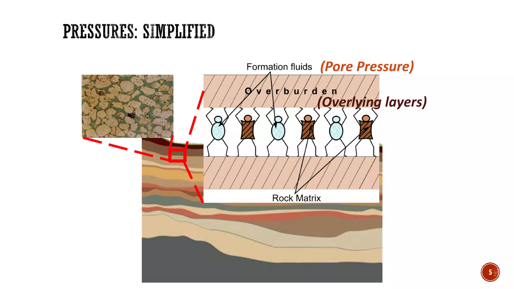
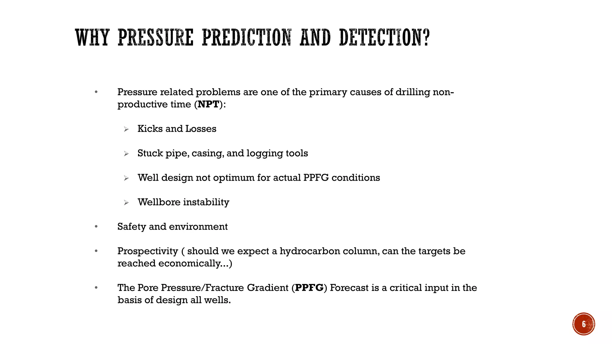
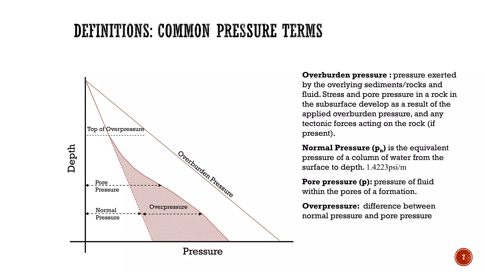
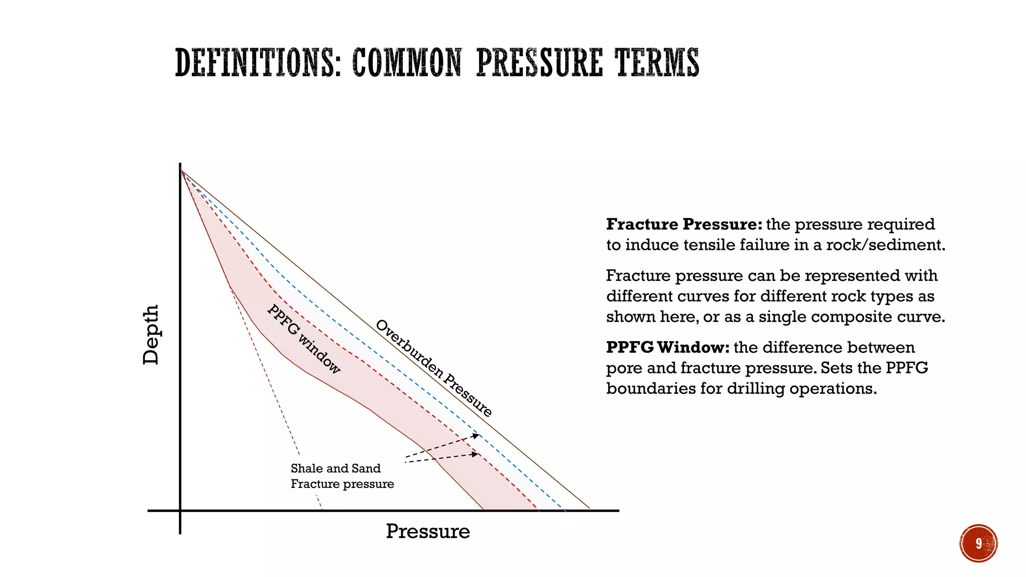
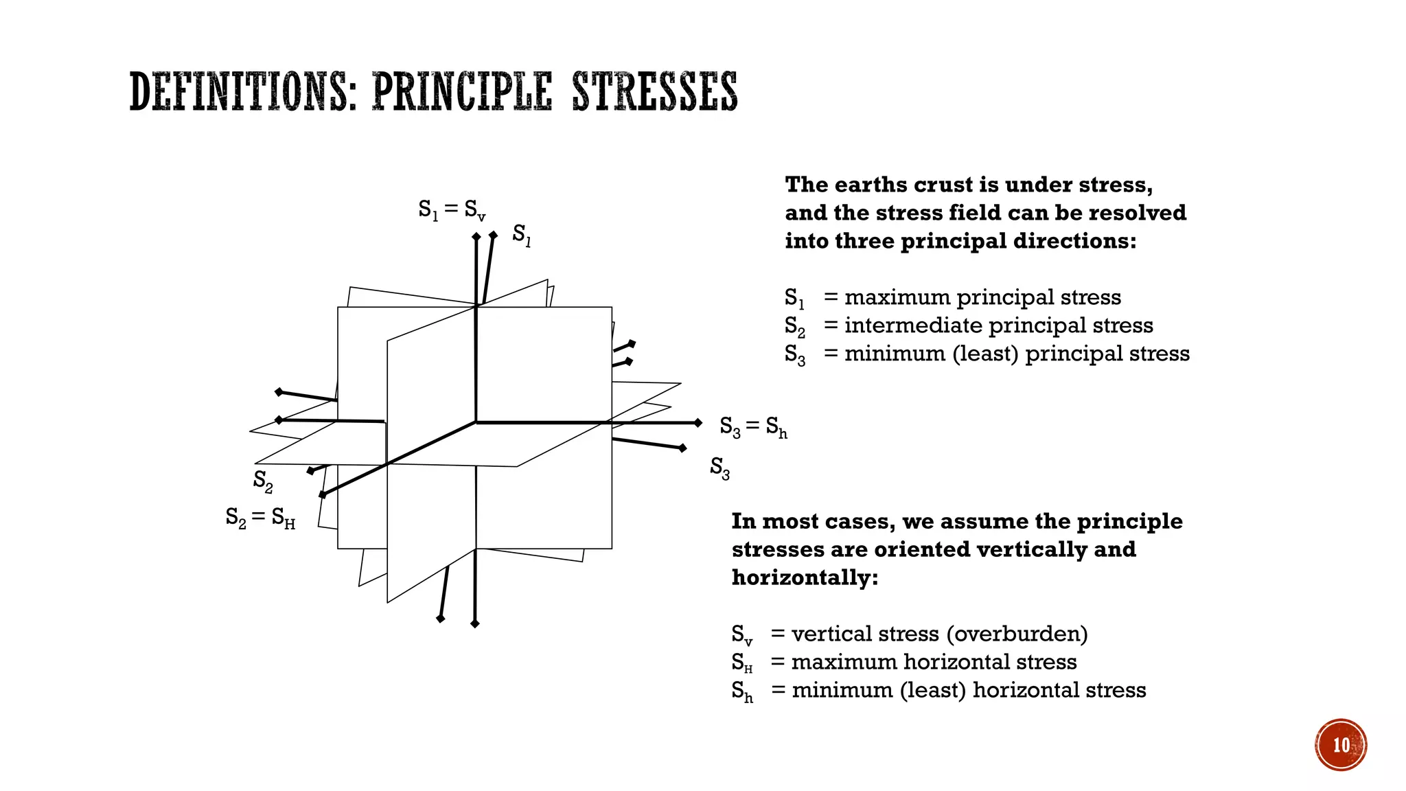
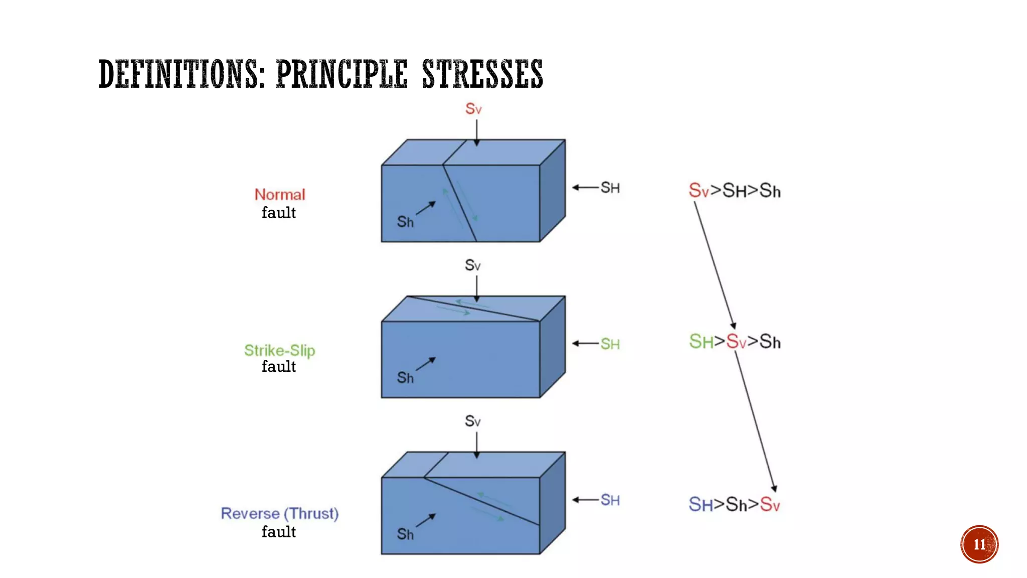
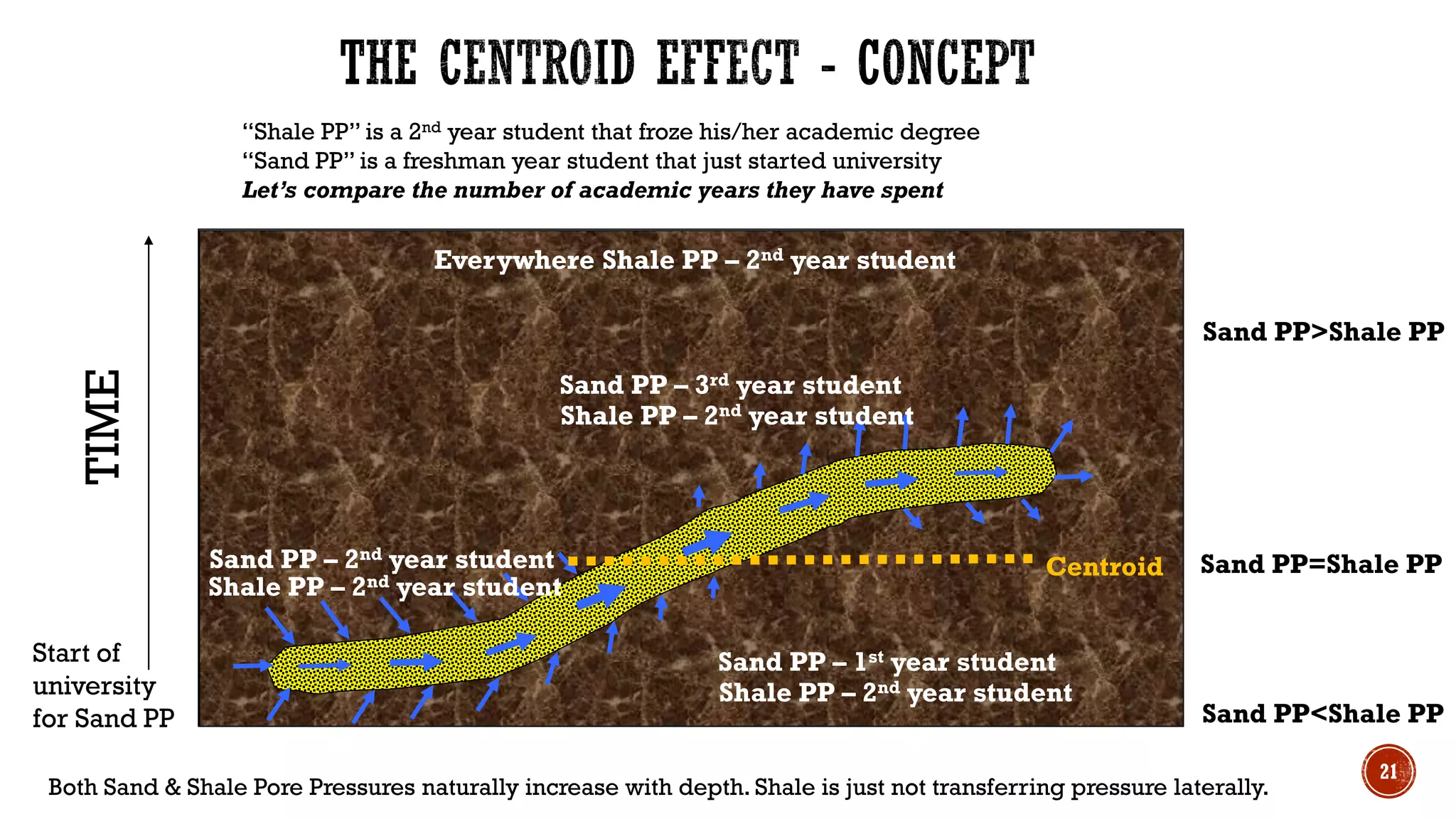
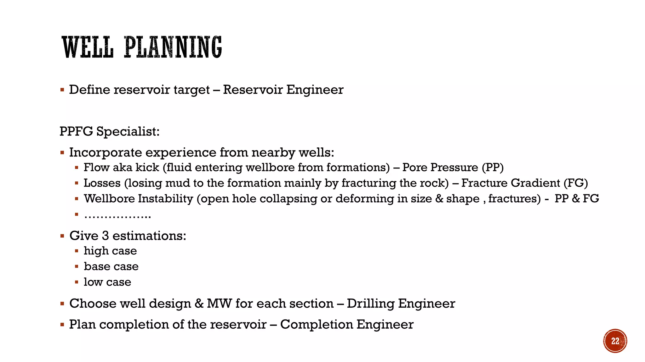
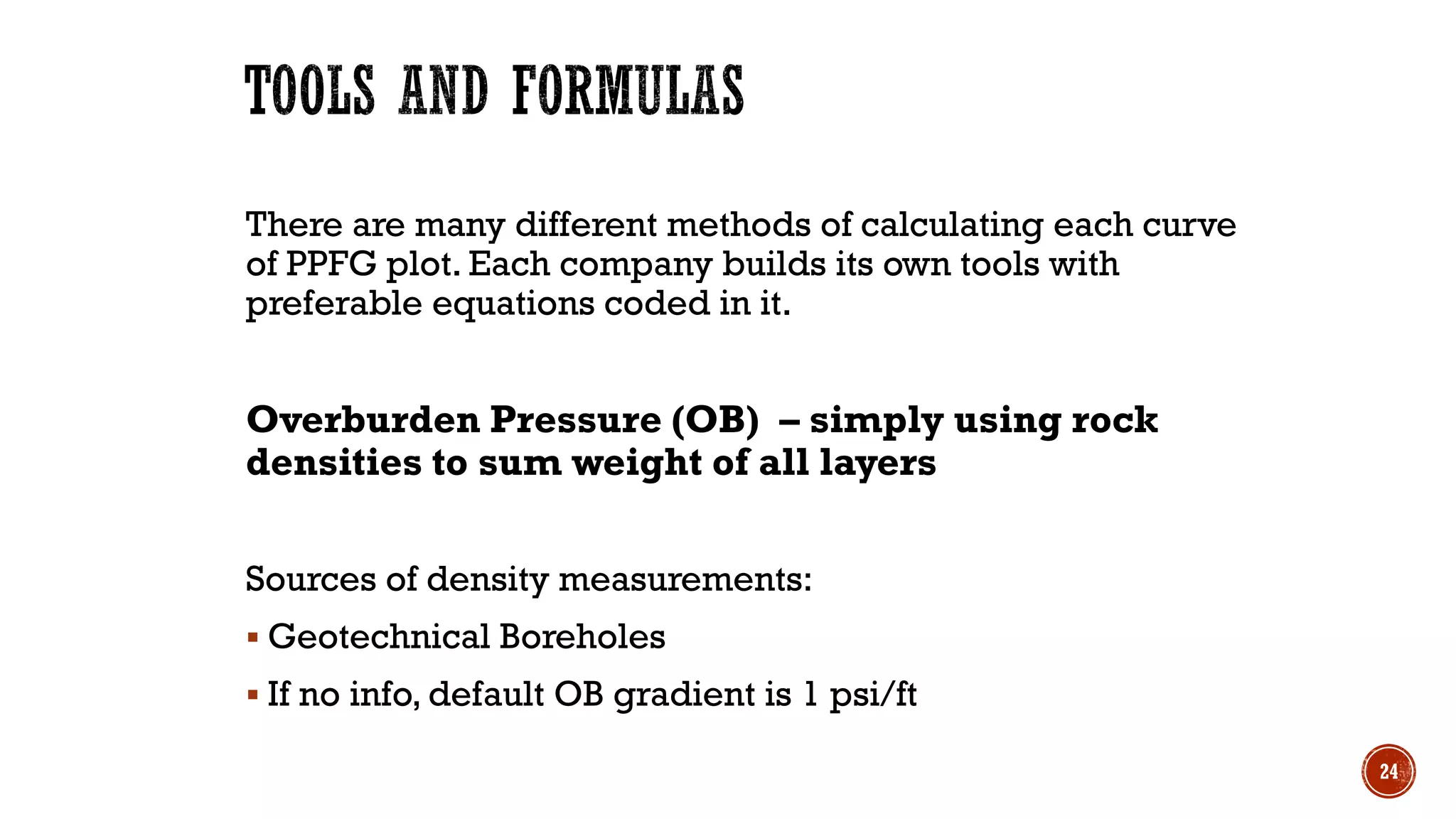
Farida Ismayilova 1
FARIDA ISMAYILOVA
>3 years working in BP. Experience as:
▪ Drilling Geohazards Specialist
▪ PPFG Specialist
Graduate of Azerbaijan State Oil and Industry University:
▪ Bachelor’s degree in Petroleum Engineering (2017)
▪ Master’s degree in Petroleum Engineering (2019)
Don’t hesitate to ask questions during the presentation
2
▪ Basics of PPFG terms & principles
Will enable further study and literature review of the topic
▪ Role of PPFG in well planning
Provide insight on how actually building PPFG works
3
BASICS OF PPFG TERMS & PRINCIPLES
4
(Pore Pressure)
(Overlying layers)
5
• Pressure related problems are one of the primary causes of drilling non-
productive time (NPT):
➢ Kicks and Losses
➢ Stuck pipe, casing, and logging tools
➢ Well design not optimum for actual PPFG conditions
➢ Wellbore instability
• Safety and environment
• Prospectivity ( should we expect a hydrocarbon column, can the targets be
reached economically...)
• The Pore Pressure/Fracture Gradient (PPFG) Forecast is a critical input in the
basis of design all wells.
6
Depth
Pressure
Top of Overpressure
Normal
Pressure
Pore
Pressure
Overburden pressure : pressure exerted
by the overlying sediments/rocks and
fluid. Stress and pore pressure in a rock in
the subsurface develop as a result of the
applied overburden pressure, and any
tectonic forces acting on the rock (if
present).
Normal Pressure (pn) is the equivalent
pressure of a column of water from the
surface to depth. 1.4223psi/m
Pore pressure (p): pressure of fluid
within the pores of a formation.
Overpressure: difference between
normal pressure and pore pressure
Overpressure
7
Depth
Pressure
Top of Overpressure
Normal
Pressure
Pore
Pressure
Vertical Effective Stress (σv
,): difference between
pore and overburden pressure.
Effective stress is the stress felt by the grain matrix
and is what causes compaction
High effective stress > well compacted > low
porosity
Low effective stress > less compacted > high
porosity
Overpressure
Vertical
Effective Stress
8
Depth
Pressure
Fracture Pressure: the pressure required
to induce tensile failure in a rock/sediment.
Fracture pressure can be represented with
different curves for different rock types as
shown here, or as a single composite curve.
PPFGWindow: the difference between
pore and fracture pressure. Sets the PPFG
boundaries for drilling operations.
Shale and Sand
Fracture pressure
9
The earths crust is under stress,
and the stress field can be resolved
into three principal directions:
S1 = maximum principal stress
S2 = intermediate principal stress
S3 = minimum (least) principal stress
S1 = Sv
S2 = SH
S3 = Sh
In most cases, we assume the principle
stresses are oriented vertically and
horizontally:
Sv = vertical stress (overburden)
SH = maximum horizontal stress
Sh = minimum (least) horizontal stress
10
11
fault
fault
fault
MudWeight (MW) ... the average density of the mud being used to
drill, run casing, complete & etc.
Units: gm/cc (grams per cubic centimeter)
ppg (pounds per gallon).
Can be measured at the surface or downhole (can differ by up to ~ 0.5
ppg), depending on the type of mud.
Equivalent Mud Weight (EMW) ... For PPFG analysis, the average
density of drilling mud that under static downhole conditions would
exactly equal the formation pressure, or fracture gradient, at a given
depth. Pressure gradient curves on a PPFG forecast represent EMW.
Both terms are pressure gradients: they describe how rapidly pressure
increases with depth, and are always referenced to a specific datum
(Kelly Bushing, Rotary Table, Sea Level, Mudline, etc...).
12
Equivalent Circulating Density (ECD):
Pressure at a certain depth while circulating
converted to density.
• ECD will vary due to changes in pump rate, MW ,
annulus size, and cuttings load.
Equivalent Static Density (ESD):
Pressure at a certain depth when not circulating
converted to density.
Density of the drilling fluid at depth (when
pumps are off)
• Generally higher than surface mud weight due to
compressibility, cuttings load, etc.
Swab Pressure: a pressure drop induced while
moving pipe in preparation for making a
connection or pulling out of hole
Time
Bottom-Hole Pressure
Connection
Connection
Pumps
Off
Activity
Drill
Drill
Increase Pump Rate
ECD Increases
Hydrostatic remains the
same
Drill
Drill Equivalent Circulating
Density
Equivalent Circulating
Density
Equivalent Circulating
Density
Hydrostatic
ESD
Hydrostatic
ESD
Swab
Swab
PP
PP
13
14
Surface MW
Mud density at surface
conditions
Pumps off = 0
Assume density &
pressure are
interchangeable for easy
understanding of the
concept
No
pressure
loss = 0
-
+
Downhole
conditions
+/-
RESULT:
EMW = ESD
15
Surface MW
Mud density at surface
conditions
Pump
pressure
to circulate
Assume density &
pressure are
interchangeable for easy
understanding of the
concept
Pressure
loss
due to
friction
-
+
Downhole
conditions
+/-
RESULT:
EMW = ECD
16
17
Depth
Pressure
Top of Overpressure
Normal
Pressure
Pore
Pressure
Overpressure
• Compaction Disequilibrium
• Smectite dehydration (Illitization)
• Lateral transfer (Charging)
As load is applied, if fluid is not
allowed to escape, the pore fluid
supports the added overburden
load, and pore pressure increases.
As excess pore pressure bleeds off
through natural permeability, the
load is transferred to the rock frame
resulting in compaction and
porosity reduction.
18
The diagenetic conversion of smectite to
illite creates overpressure as follows:
• Increasing volume of fluids within pore
space of confined system
• Precipitating by-products, which form
permeability barriers
• Collapsing clay structure and transferring
a greater proportion of the total stress to
pore fluid.
12.6% Pore Water
10% Dry Smectite
2.4% Bound Water
41% Illite
34% Other Minerals
And Clays
6% Pore Water
36% Dry Smectite
9% Bound Water
15% Illite
34% Other Minerals
And Clays
19
Permeable, brine filled
formations transfer &
distribute pressure
• Sands drilled up dip have the
same overpressure as down dip,
but pore pressure gradient
(mudweight equivalent) is higher
updip than downdip.
Centroid: the depth at
which fluid flow between
sand and shale is zero
(where pore pressure in
the sand is equal to pore
pressure in the bounding
shale).
Sea level
Mud line
Centroid
20
Sand Pore Pressure (PP) >Shale PP
Sand PP = Shale PP
Sand PP<Shale PP
21
Both Sand & Shale Pore Pressures naturally increase with depth. Shale is just not transferring pressure laterally.
TIME
Mud line
Centroid
Everywhere Shale PP – 2nd year student
Sand PP – 2nd year student
Sand PP>Shale PP
Sand PP=Shale PP
Sand PP<Shale PP
Sand PP – 3rd year student
Sand PP – 1st year student
Shale PP – 2nd year student
Start of
university
for Sand PP
“Shale PP” is a 2nd year student that froze his/her academic degree
“Sand PP” is a freshman year student that just started university
Let’s compare the number of academic years they have spent
▪ Define reservoir target – Reservoir Engineer
PPFG Specialist:
▪ Incorporate experience from nearby wells:
▪ Flow aka kick (fluid entering wellbore from formations) – Pore Pressure (PP)
▪ Losses (losing mud to the formation mainly by fracturing the rock) – Fracture Gradient (FG)
▪ Wellbore Instability (open hole collapsing or deforming in size & shape , fractures) - PP & FG
▪ ……………..
▪ Give 3 estimations:
▪ high case
▪ base case
▪ low case
▪ Choose well design & MW for each section – Drilling Engineer
▪ Plan completion of the reservoir – Completion Engineer
22
ROLE OF PPFG IN WELL PLANNING
23
There are many different methods of calculating each curve
of PPFG plot. Each company builds its own tools with
preferable equations coded in it.
Overburden Pressure (OB) – simply using rock
densities to sum weight of all layers
Sources of density measurements:
▪ Geotechnical Boreholes
▪ If no info, default OB gradient is 1 psi/ft
24
FG Sand - Eaton’s Equation
K0 (key note) – is a coefficient
FG Shale - Brumfield’s Equation (Empirical)
PP - Presgraf equation, Pressure measurement
Sand Fracture
Gradient
PP
k0
OB
25
There is an oil & gas prospect, target:
1. Can you drill and complete a well to reach it? – Feasibility –
planned PPFG
You decide to drill and complete a well:
2. How should you drill & complete the well? – Safe & optimal
well design & Mud Weight (MW), completion plan – planned PPFG
You are drilling a well:
3. Is everything going smoothly as planned? – Monitoring, adjusting
PPFG – real-time PPFG
You finished the well and will plan another soon:
4. What have you learnt? What will it change for your next well?
– post-drill PPFG 26
1. Where to set Casing/Liner shoes?
Will FG at previous shoe depth be sufficient for drilling and cementing
the whole section?
Notes:
Previous shoe depth is usually the weakest point in the
section with lowest FG and risk of mud losses into the
formation.
Typically casing setting depths are chosen from top to
bottom (there is bottom-top too see Heriott-Watt Drilling
book). Reasons:
▪ 1st set casing – conductor defines your starting point
▪ Overpressure (when pressure is higher than hydrostatic
pressure 0.45psi/ft ) starts from shallow depth 27
2. What MudWeight (MW) to
use?
You don’t want to have mud losses to the formation
(losses) or fluids coming from formations (flow)!
Notes:
Losses - happen when drilling pressure > FG
Flow - occurs when drilling pressure < PP
28
FIELD TIMELINE
Only
Seismic
Pilot hole
Geotechnic
al
boreholes
1st
exploration
well
(wildcat)
Development:
drilling more
Is there
oil and
gas?
Is it safe to put
a rig? If yes,
you need initial
info
Well down to the
prospect. New
info. Drill more
wells?
Many more
wells,
production &
experience
29
30

Basic Pressure Concepts

  • 1.
  • 2.
    FARIDA ISMAYILOVA >3 yearsworking in BP. Experience as: ▪ Drilling Geohazards Specialist ▪ PPFG Specialist Graduate of Azerbaijan State Oil and Industry University: ▪ Bachelor’s degree in Petroleum Engineering (2017) ▪ Master’s degree in Petroleum Engineering (2019) Don’t hesitate to ask questions during the presentation 2
  • 3.
    ▪ Basics ofPPFG terms & principles Will enable further study and literature review of the topic ▪ Role of PPFG in well planning Provide insight on how actually building PPFG works 3
  • 4.
    BASICS OF PPFGTERMS & PRINCIPLES 4
  • 5.
  • 6.
    • Pressure relatedproblems are one of the primary causes of drilling non- productive time (NPT): ➢ Kicks and Losses ➢ Stuck pipe, casing, and logging tools ➢ Well design not optimum for actual PPFG conditions ➢ Wellbore instability • Safety and environment • Prospectivity ( should we expect a hydrocarbon column, can the targets be reached economically...) • The Pore Pressure/Fracture Gradient (PPFG) Forecast is a critical input in the basis of design all wells. 6
  • 7.
    Depth Pressure Top of Overpressure Normal Pressure Pore Pressure Overburdenpressure : pressure exerted by the overlying sediments/rocks and fluid. Stress and pore pressure in a rock in the subsurface develop as a result of the applied overburden pressure, and any tectonic forces acting on the rock (if present). Normal Pressure (pn) is the equivalent pressure of a column of water from the surface to depth. 1.4223psi/m Pore pressure (p): pressure of fluid within the pores of a formation. Overpressure: difference between normal pressure and pore pressure Overpressure 7
  • 8.
    Depth Pressure Top of Overpressure Normal Pressure Pore Pressure VerticalEffective Stress (σv ,): difference between pore and overburden pressure. Effective stress is the stress felt by the grain matrix and is what causes compaction High effective stress > well compacted > low porosity Low effective stress > less compacted > high porosity Overpressure Vertical Effective Stress 8
  • 9.
    Depth Pressure Fracture Pressure: thepressure required to induce tensile failure in a rock/sediment. Fracture pressure can be represented with different curves for different rock types as shown here, or as a single composite curve. PPFGWindow: the difference between pore and fracture pressure. Sets the PPFG boundaries for drilling operations. Shale and Sand Fracture pressure 9
  • 10.
    The earths crustis under stress, and the stress field can be resolved into three principal directions: S1 = maximum principal stress S2 = intermediate principal stress S3 = minimum (least) principal stress S1 = Sv S2 = SH S3 = Sh In most cases, we assume the principle stresses are oriented vertically and horizontally: Sv = vertical stress (overburden) SH = maximum horizontal stress Sh = minimum (least) horizontal stress 10
  • 11.
  • 12.
    MudWeight (MW) ...the average density of the mud being used to drill, run casing, complete & etc. Units: gm/cc (grams per cubic centimeter) ppg (pounds per gallon). Can be measured at the surface or downhole (can differ by up to ~ 0.5 ppg), depending on the type of mud. Equivalent Mud Weight (EMW) ... For PPFG analysis, the average density of drilling mud that under static downhole conditions would exactly equal the formation pressure, or fracture gradient, at a given depth. Pressure gradient curves on a PPFG forecast represent EMW. Both terms are pressure gradients: they describe how rapidly pressure increases with depth, and are always referenced to a specific datum (Kelly Bushing, Rotary Table, Sea Level, Mudline, etc...). 12
  • 13.
    Equivalent Circulating Density(ECD): Pressure at a certain depth while circulating converted to density. • ECD will vary due to changes in pump rate, MW , annulus size, and cuttings load. Equivalent Static Density (ESD): Pressure at a certain depth when not circulating converted to density. Density of the drilling fluid at depth (when pumps are off) • Generally higher than surface mud weight due to compressibility, cuttings load, etc. Swab Pressure: a pressure drop induced while moving pipe in preparation for making a connection or pulling out of hole Time Bottom-Hole Pressure Connection Connection Pumps Off Activity Drill Drill Increase Pump Rate ECD Increases Hydrostatic remains the same Drill Drill Equivalent Circulating Density Equivalent Circulating Density Equivalent Circulating Density Hydrostatic ESD Hydrostatic ESD Swab Swab PP PP 13
  • 14.
    14 Surface MW Mud densityat surface conditions Pumps off = 0 Assume density & pressure are interchangeable for easy understanding of the concept No pressure loss = 0 - + Downhole conditions +/- RESULT: EMW = ESD
  • 15.
    15 Surface MW Mud densityat surface conditions Pump pressure to circulate Assume density & pressure are interchangeable for easy understanding of the concept Pressure loss due to friction - + Downhole conditions +/- RESULT: EMW = ECD
  • 16.
  • 17.
    17 Depth Pressure Top of Overpressure Normal Pressure Pore Pressure Overpressure •Compaction Disequilibrium • Smectite dehydration (Illitization) • Lateral transfer (Charging)
  • 18.
    As load isapplied, if fluid is not allowed to escape, the pore fluid supports the added overburden load, and pore pressure increases. As excess pore pressure bleeds off through natural permeability, the load is transferred to the rock frame resulting in compaction and porosity reduction. 18
  • 19.
    The diagenetic conversionof smectite to illite creates overpressure as follows: • Increasing volume of fluids within pore space of confined system • Precipitating by-products, which form permeability barriers • Collapsing clay structure and transferring a greater proportion of the total stress to pore fluid. 12.6% Pore Water 10% Dry Smectite 2.4% Bound Water 41% Illite 34% Other Minerals And Clays 6% Pore Water 36% Dry Smectite 9% Bound Water 15% Illite 34% Other Minerals And Clays 19
  • 20.
    Permeable, brine filled formationstransfer & distribute pressure • Sands drilled up dip have the same overpressure as down dip, but pore pressure gradient (mudweight equivalent) is higher updip than downdip. Centroid: the depth at which fluid flow between sand and shale is zero (where pore pressure in the sand is equal to pore pressure in the bounding shale). Sea level Mud line Centroid 20 Sand Pore Pressure (PP) >Shale PP Sand PP = Shale PP Sand PP<Shale PP
  • 21.
    21 Both Sand &Shale Pore Pressures naturally increase with depth. Shale is just not transferring pressure laterally. TIME Mud line Centroid Everywhere Shale PP – 2nd year student Sand PP – 2nd year student Sand PP>Shale PP Sand PP=Shale PP Sand PP<Shale PP Sand PP – 3rd year student Sand PP – 1st year student Shale PP – 2nd year student Shale PP – 2nd year student Shale PP – 2nd year student Start of university for Sand PP “Shale PP” is a 2nd year student that froze his/her academic degree “Sand PP” is a freshman year student that just started university Let’s compare the number of academic years they have spent
  • 22.
    ▪ Define reservoirtarget – Reservoir Engineer PPFG Specialist: ▪ Incorporate experience from nearby wells: ▪ Flow aka kick (fluid entering wellbore from formations) – Pore Pressure (PP) ▪ Losses (losing mud to the formation mainly by fracturing the rock) – Fracture Gradient (FG) ▪ Wellbore Instability (open hole collapsing or deforming in size & shape , fractures) - PP & FG ▪ …………….. ▪ Give 3 estimations: ▪ high case ▪ base case ▪ low case ▪ Choose well design & MW for each section – Drilling Engineer ▪ Plan completion of the reservoir – Completion Engineer 22
  • 23.
    ROLE OF PPFGIN WELL PLANNING 23
  • 24.
    There are manydifferent methods of calculating each curve of PPFG plot. Each company builds its own tools with preferable equations coded in it. Overburden Pressure (OB) – simply using rock densities to sum weight of all layers Sources of density measurements: ▪ Geotechnical Boreholes ▪ If no info, default OB gradient is 1 psi/ft 24
  • 25.
    FG Sand -Eaton’s Equation K0 (key note) – is a coefficient FG Shale - Brumfield’s Equation (Empirical) PP - Presgraf equation, Pressure measurement Sand Fracture Gradient PP k0 OB 25
  • 26.
    There is anoil & gas prospect, target: 1. Can you drill and complete a well to reach it? – Feasibility – planned PPFG You decide to drill and complete a well: 2. How should you drill & complete the well? – Safe & optimal well design & Mud Weight (MW), completion plan – planned PPFG You are drilling a well: 3. Is everything going smoothly as planned? – Monitoring, adjusting PPFG – real-time PPFG You finished the well and will plan another soon: 4. What have you learnt? What will it change for your next well? – post-drill PPFG 26
  • 27.
    1. Where toset Casing/Liner shoes? Will FG at previous shoe depth be sufficient for drilling and cementing the whole section? Notes: Previous shoe depth is usually the weakest point in the section with lowest FG and risk of mud losses into the formation. Typically casing setting depths are chosen from top to bottom (there is bottom-top too see Heriott-Watt Drilling book). Reasons: ▪ 1st set casing – conductor defines your starting point ▪ Overpressure (when pressure is higher than hydrostatic pressure 0.45psi/ft ) starts from shallow depth 27
  • 28.
    2. What MudWeight(MW) to use? You don’t want to have mud losses to the formation (losses) or fluids coming from formations (flow)! Notes: Losses - happen when drilling pressure > FG Flow - occurs when drilling pressure < PP 28
  • 29.
    FIELD TIMELINE Only Seismic Pilot hole Geotechnic al boreholes 1st exploration well (wildcat) Development: drillingmore Is there oil and gas? Is it safe to put a rig? If yes, you need initial info Well down to the prospect. New info. Drill more wells? Many more wells, production & experience 29
  • 30.