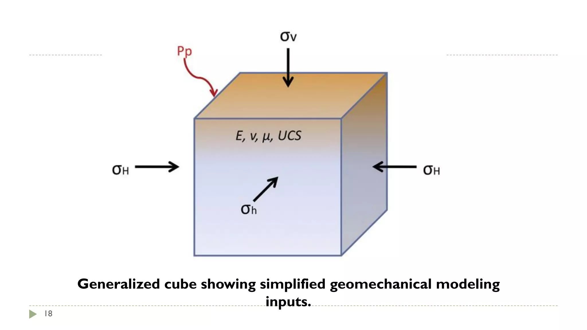
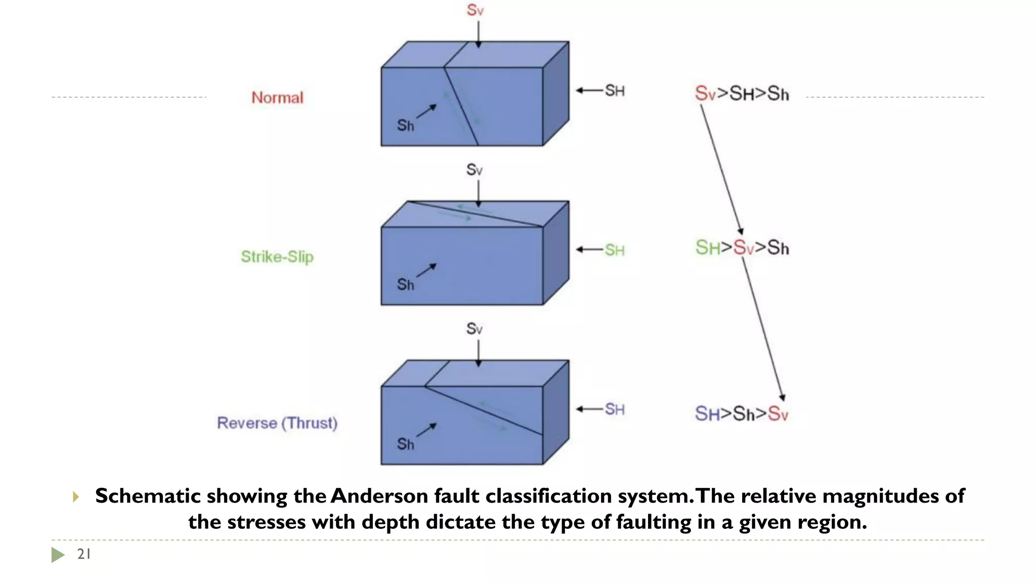
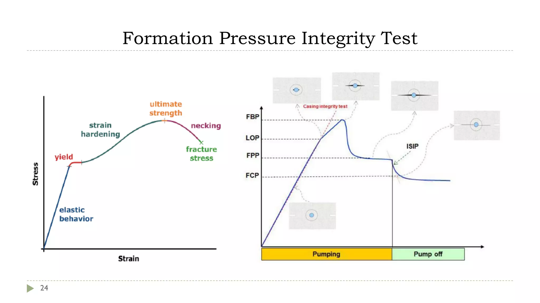
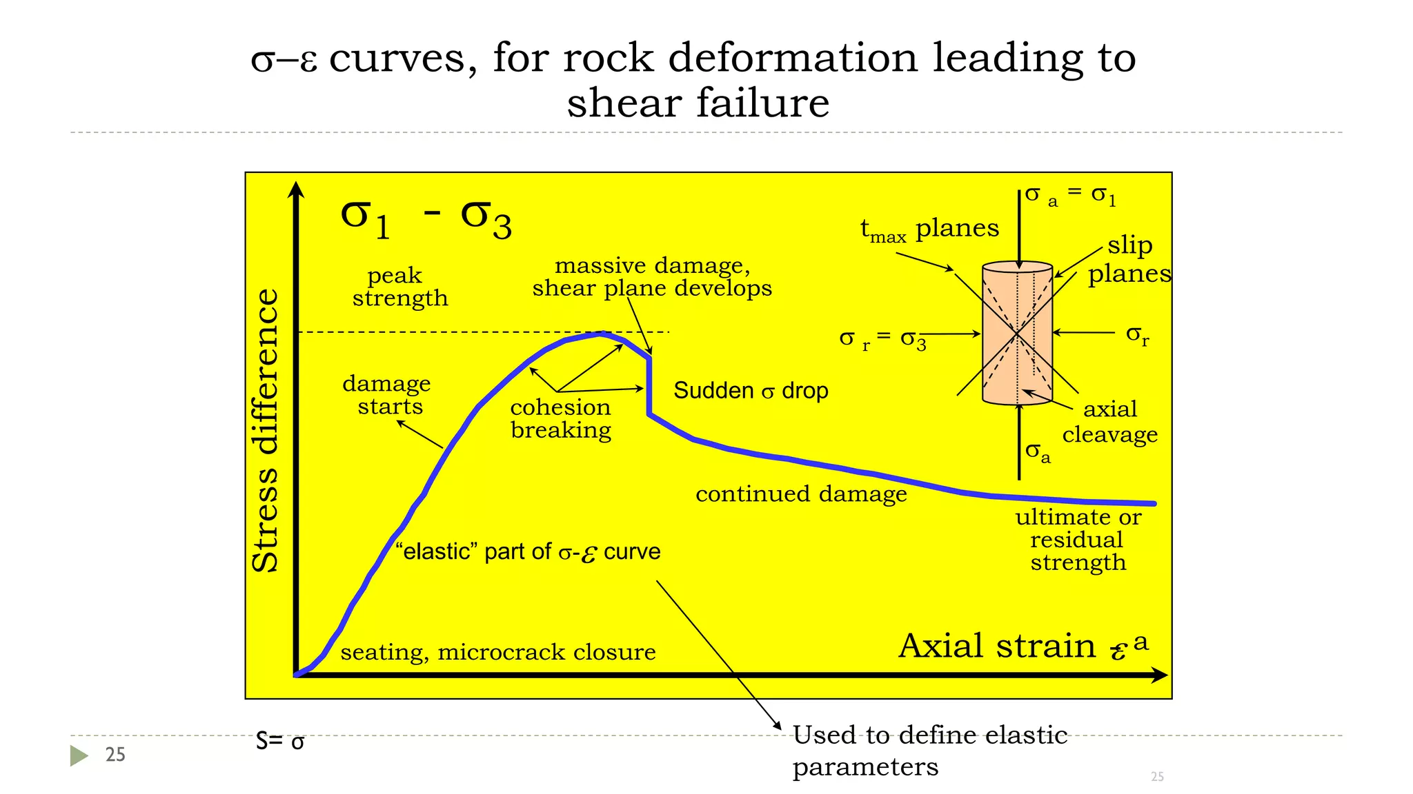
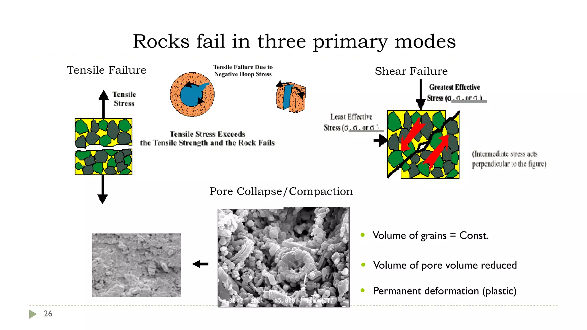
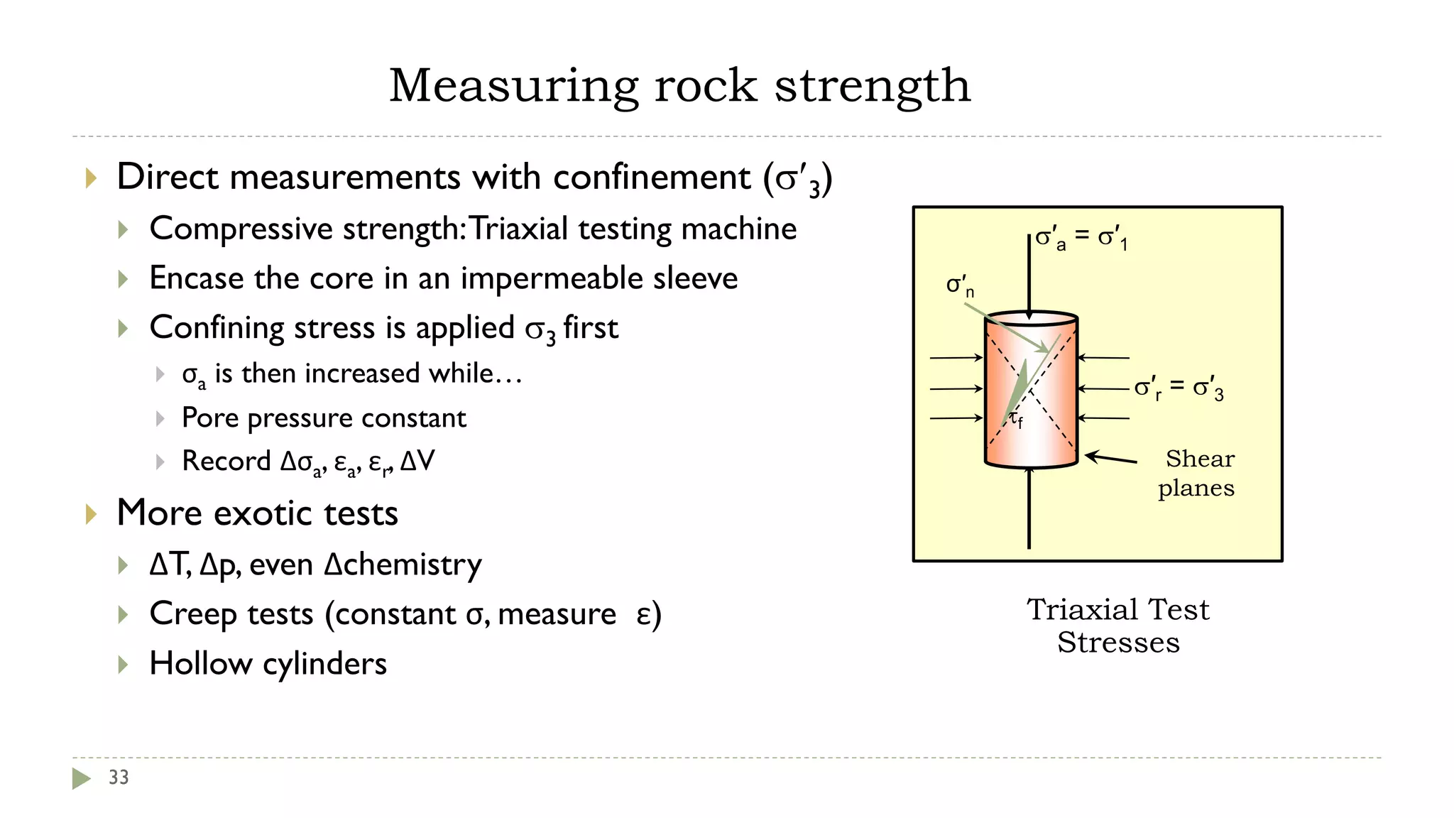
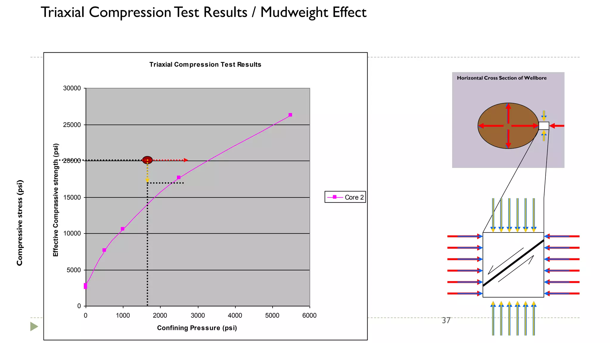
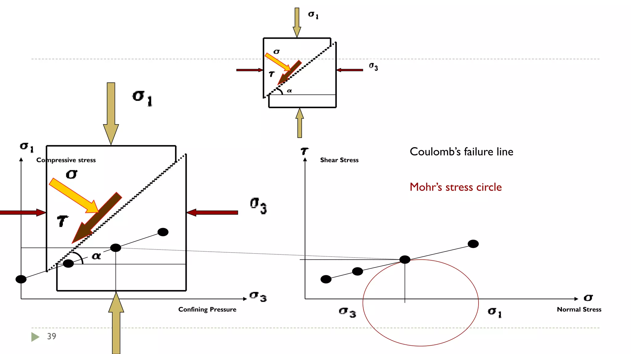
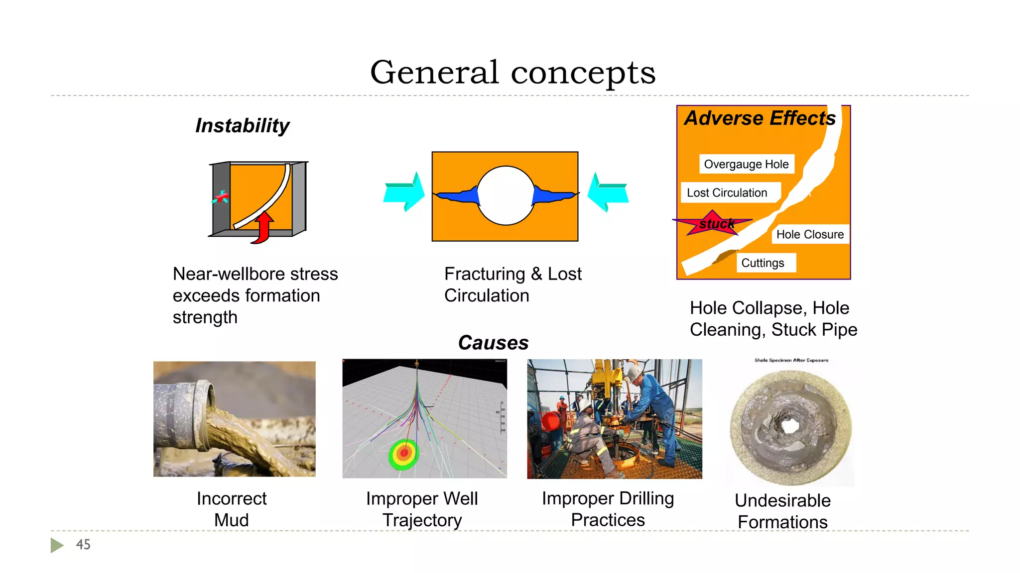
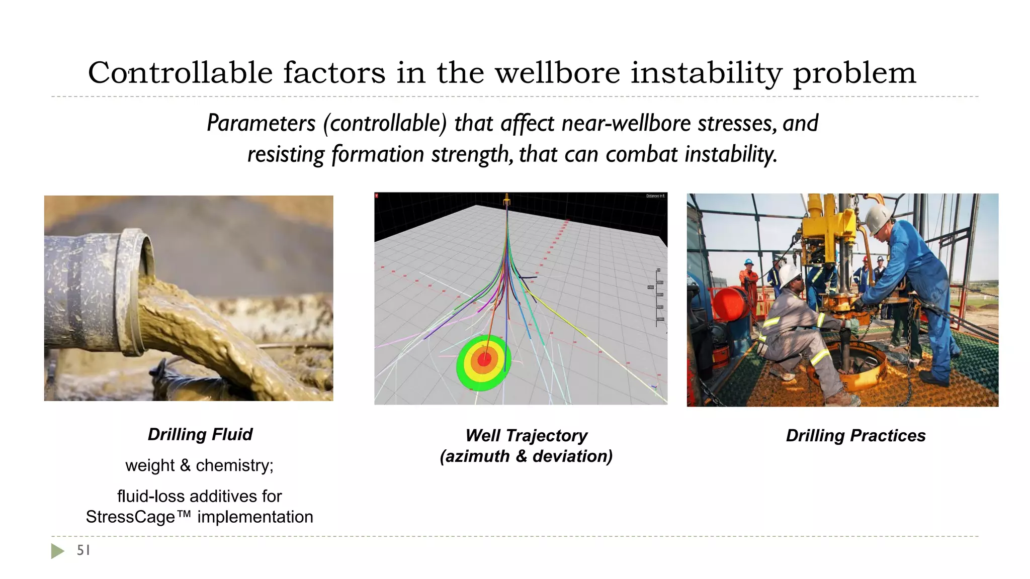
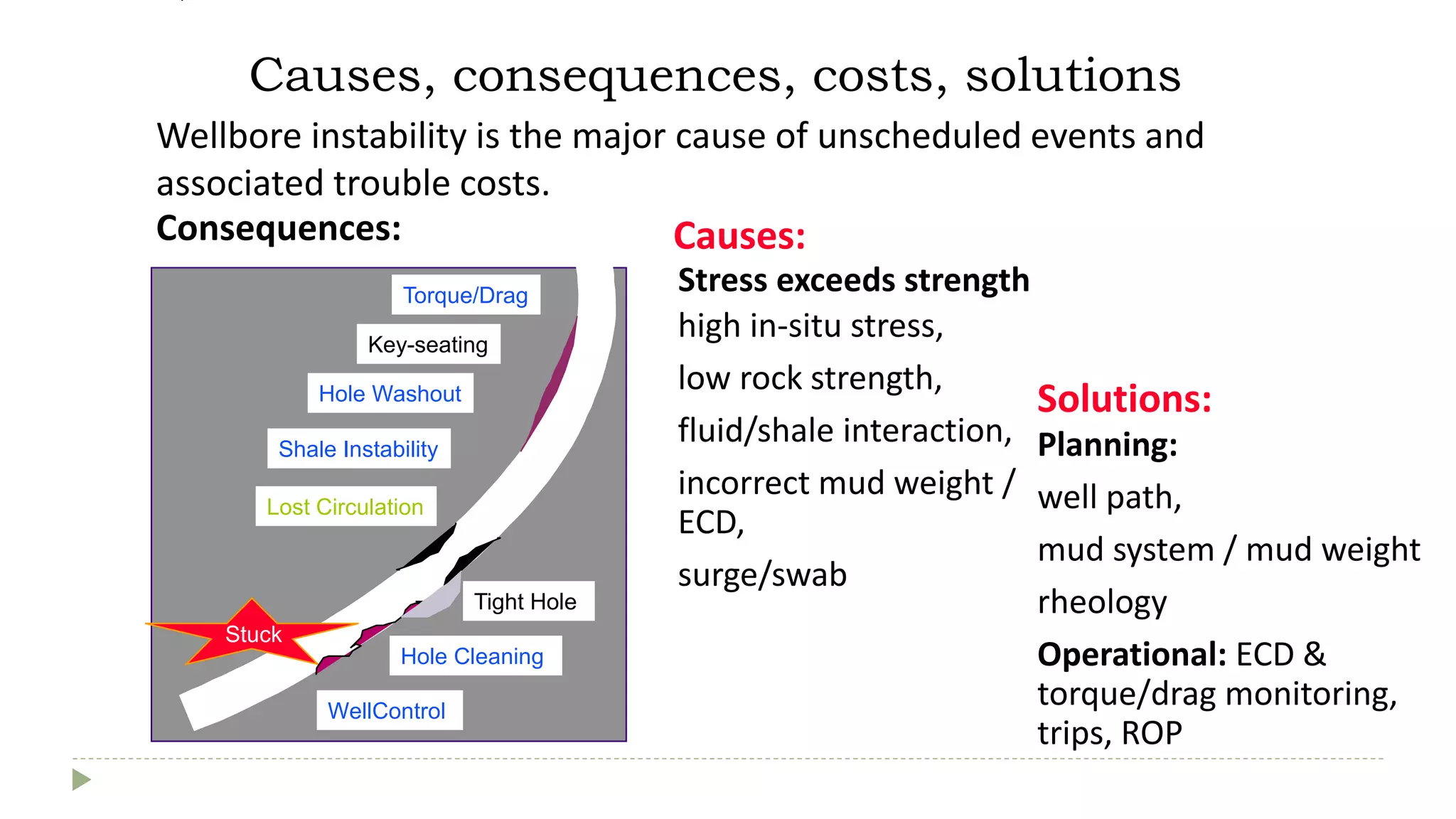
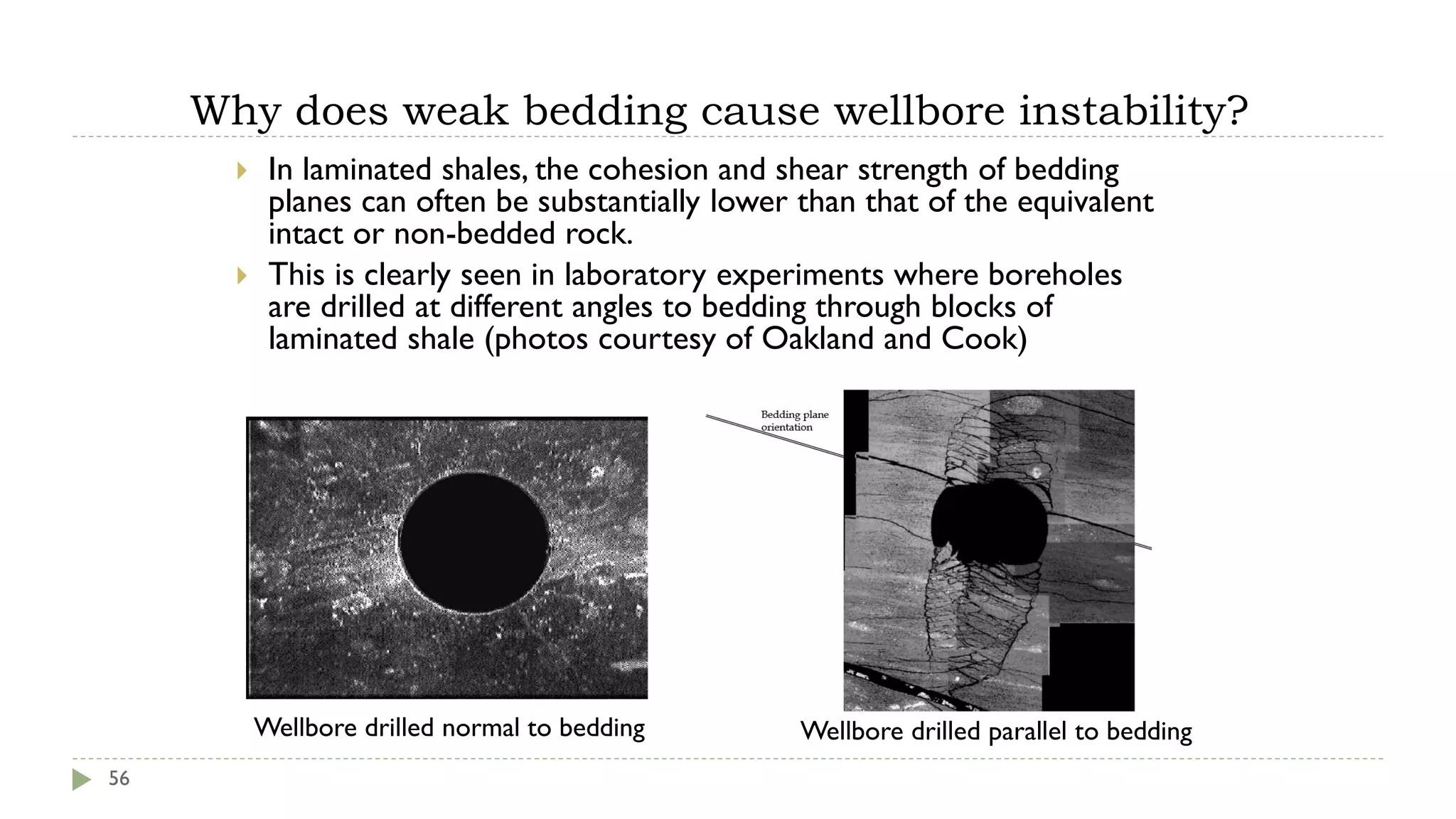
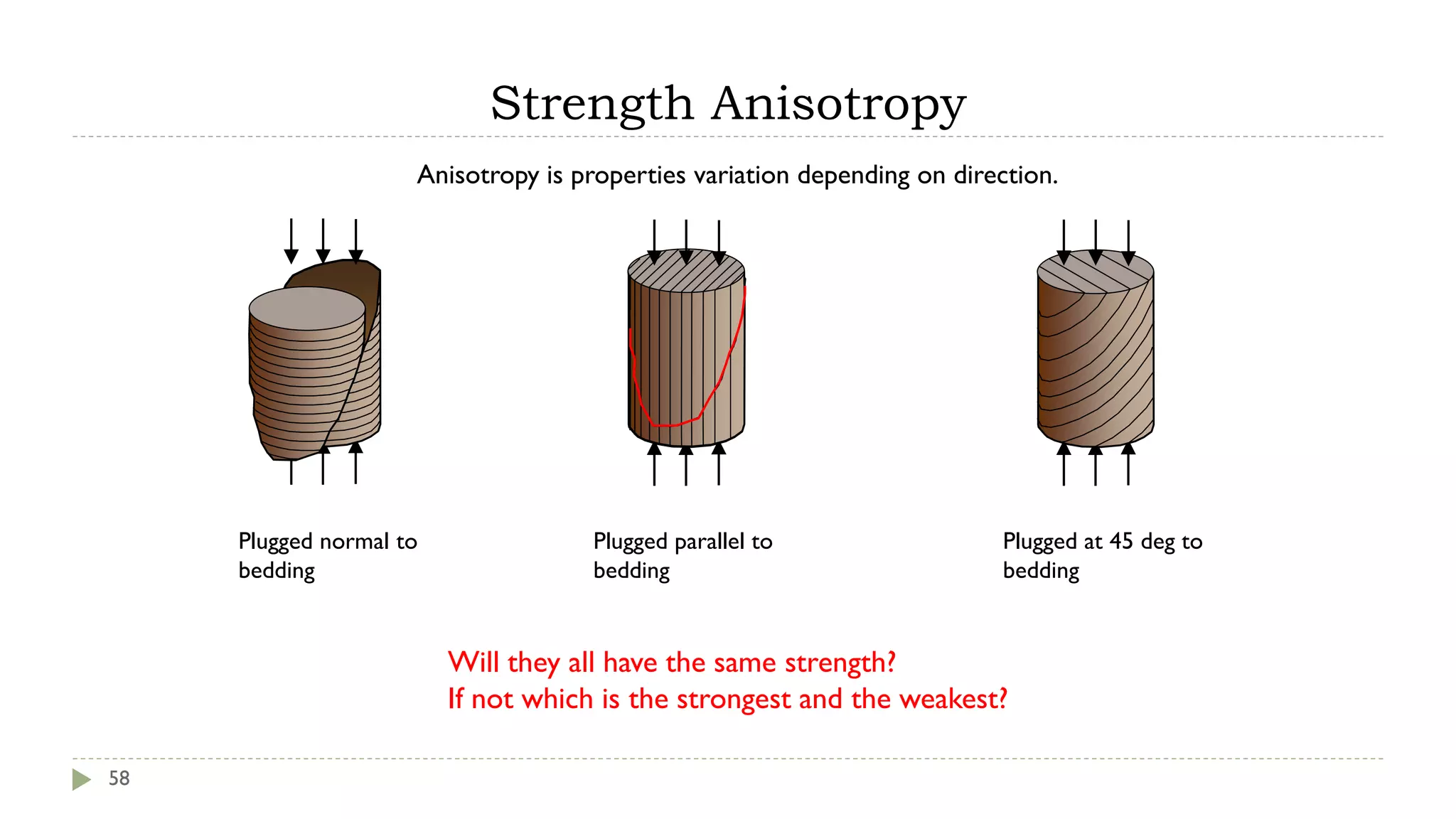
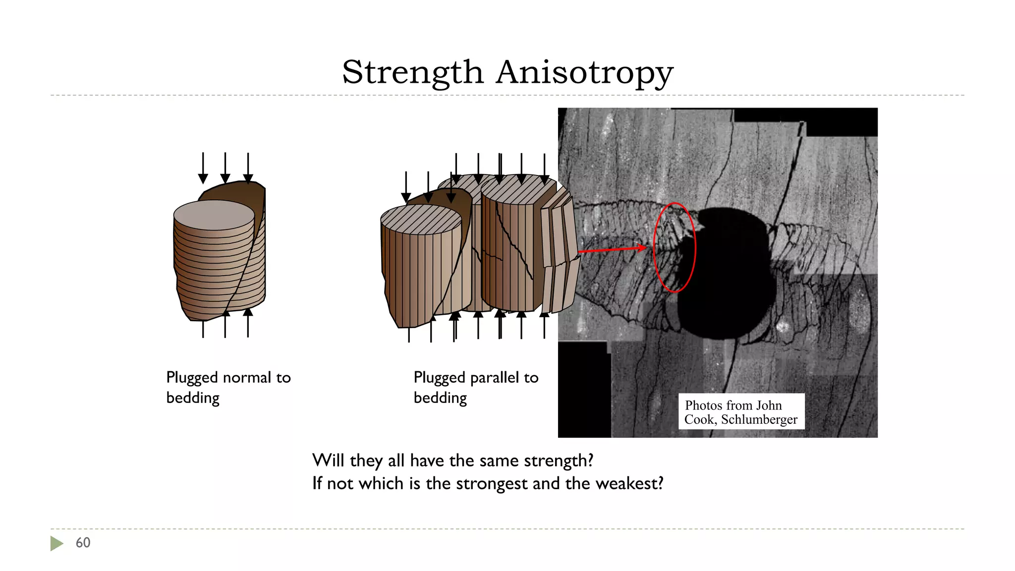
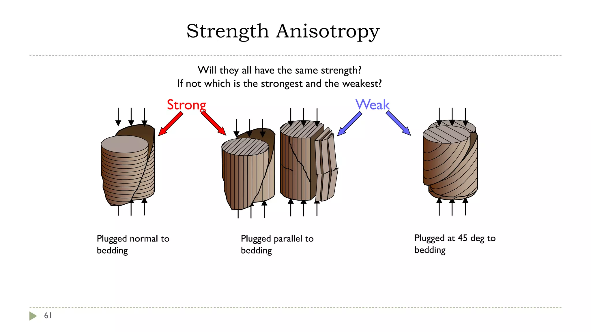
The extensive slide-pack starts with introducing physics and basics on geomechanics. A lot of stress and rock strength concepts are explored. Then it moves on to explain the importance of the discipline for drilling, injection, sanding. Apart from giving theory to understand more difficult content that follow, it throws in practical application and prepares good ground for further study of geomechanical literature.
Stress analysis is the essence that is needed while planning exploration, drilling and development operations in oil and gas industries. Proper knowledge of Geomechanics will help us to reduce the risk of failure as well as provide a better picture of stresses inside the earth. From Hydrofracturing to directional drilling, stresses play their parts.
That is my presentation for my grad research about reservoir geomechanics, hope you find it useful, and my source book was reservoir geomechanics for prof Mark Zoback, soon the PDF copy will be available as well.
Briefly explaining the basics of Pore Pressure Fracture Gradient (PPFG) plot & its role in planning, drilling & decision making. Please, refer to my "Formation pressure" upload for more details on pressure concepts.
The presentation highlights the root causes of major drilling issues such as formation pressure uncertainty, subsurface feature like mud volcanoes, major fault, poor well planning & etc. Then it elaborates on consequences of all above on examples of wellbore instability, sticking, gumbo & so on.
The borehole environment are created by the drilling process.
It begins with the fluid within the borehole which is usually drilling mud but can be air or water.
The resistivity of the borehole fluid is referred to as Rm.
During a period of erosion and sedimentation, grains of sediment are continuously building up on top of each other, generally in a water filled environment. As the thickness of the layer of sediment increases, the grains of the sediment are packed closer together, and some of the water is expelled from the pore spaces. However, if the pore throats through the sediment are interconnecting all the way to surface the pressure of the fluid at any depth in the sediment will be same as that which would be found in a simple colom of fluid. The pressure in the fluid in the pores of the sediment will only be dependent on the density of the fluid in the pore space and the depth of the pressure measurement (equal to the height of the colom of liquid). it will be independent of the pore size or pore throat geometry.
calculating reservoir pressure, knowing Depth of gas-oil. oil water interface, GOC AND WOC, numeric method to calculate interface. importance of isobaric maps in estimating reservoir pressure.
Introduction first starts by explaining sedimentation of reservoir rocks. Then it moves on to trap elements and responsibilities of a reservoir engineer.
A saturated set of slides that talk about multiple drilling equipment processes & aspects. Examples: rig types, systems, drilling mud, bits, pipes & etc.
Özüllər və qazma qurğuları, sistemləri, qazma baltaları və daha bir çox avadanlıq və proses barədə məlumat. Ən sonda istifadə olunan terminlərin ingiliscə tərcüməsi verilmişdir.
The slide-pack covers a large variety of artificial lift methods. Explanations are supported by breakdown of pros and cons, calculations and questions. Questions will shed light of roughly how to decide which method(s) to use in a specific case.
The slides cover reservoir/fluid properties and production parameters of the Zhetybay oil and gas field located in Khazakstan. Information about geology, porosity-permeability, production and injection allow you to get an idea about drive mechanisms in the field.
Abstracts are saturated summary of a research work and is part of academics writing. When applying for conferences, neat structure of an abstract can guarantee admission.
The content defines geophysics and focuses on roles of seismic on exploration, well planning. It provides insights on integration of various disciplines.
The importance of geohazards for safety, rig/well integrity & drilling. It includes real incidents & worst case scenarios. Pressure concepts, seismic and diagrams are utilized to explain given examples.
Global warming concerns leading to decarbonization is shifting energy from fossil fuels to renewable energy. The slides briefly touch on different ways of decarbonizing & alternative energy resources.
Exploring formation pressures based on Chapter 5 of Heriot-Watt Drilling Engineering book. Pressure prediction, well planning, well bore stability aspects are also covered in the slide-pack.
Geocience skills have a place in the future. Geophysical & geotechnical data, interpretation will be required for identifying the best places & ways to install wind turbines.
Skin effekti - quyuətrafı zonada müxtəlif səbəblərdən keçiriciliyin dəyişməsi
Təqdimat skin anlayışı, onun səbəbləri, növləri barədə informasiya verir.
Təqdimatda animasiya olduğu üçün təqdimatı yükləyib baxın.
Təqdimat qazma qurğularının növləri, komponentləri,qazma məhlulunun sirkulyasiyası və təmizlənməsi prosesi və avadanlıqları və s. barədə qısa məlumat verir.
NO1 Uk best vashikaran specialist in delhi vashikaran baba near me online vas...Amil Baba Dawood bangali
Contact with Dawood Bhai Just call on +92322-6382012 and we'll help you. We'll solve all your problems within 12 to 24 hours and with 101% guarantee and with astrology systematic. If you want to take any personal or professional advice then also you can call us on +92322-6382012 , ONLINE LOVE PROBLEM & Other all types of Daily Life Problem's.Then CALL or WHATSAPP us on +92322-6382012 and Get all these problems solutions here by Amil Baba DAWOOD BANGALI
#vashikaranspecialist #astrologer #palmistry #amliyaat #taweez #manpasandshadi #horoscope #spiritual #lovelife #lovespell #marriagespell#aamilbabainpakistan #amilbabainkarachi #powerfullblackmagicspell #kalajadumantarspecialist #realamilbaba #AmilbabainPakistan #astrologerincanada #astrologerindubai #lovespellsmaster #kalajaduspecialist #lovespellsthatwork #aamilbabainlahore#blackmagicformarriage #aamilbaba #kalajadu #kalailam #taweez #wazifaexpert #jadumantar #vashikaranspecialist #astrologer #palmistry #amliyaat #taweez #manpasandshadi #horoscope #spiritual #lovelife #lovespell #marriagespell#aamilbabainpakistan #amilbabainkarachi #powerfullblackmagicspell #kalajadumantarspecialist #realamilbaba #AmilbabainPakistan #astrologerincanada #astrologerindubai #lovespellsmaster #kalajaduspecialist #lovespellsthatwork #aamilbabainlahore #blackmagicforlove #blackmagicformarriage #aamilbaba #kalajadu #kalailam #taweez #wazifaexpert #jadumantar #vashikaranspecialist #astrologer #palmistry #amliyaat #taweez #manpasandshadi #horoscope #spiritual #lovelife #lovespell #marriagespell#aamilbabainpakistan #amilbabainkarachi #powerfullblackmagicspell #kalajadumantarspecialist #realamilbaba #AmilbabainPakistan #astrologerincanada #astrologerindubai #lovespellsmaster #kalajaduspecialist #lovespellsthatwork #aamilbabainlahore #Amilbabainuk #amilbabainspain #amilbabaindubai #Amilbabainnorway #amilbabainkrachi #amilbabainlahore #amilbabaingujranwalan #amilbabainislamabad
Immunizing Image Classifiers Against Localized Adversary Attacksgerogepatton
This paper addresses the vulnerability of deep learning models, particularly convolutional neural networks
(CNN)s, to adversarial attacks and presents a proactive training technique designed to counter them. We
introduce a novel volumization algorithm, which transforms 2D images into 3D volumetric representations.
When combined with 3D convolution and deep curriculum learning optimization (CLO), itsignificantly improves
the immunity of models against localized universal attacks by up to 40%. We evaluate our proposed approach
using contemporary CNN architectures and the modified Canadian Institute for Advanced Research (CIFAR-10
and CIFAR-100) and ImageNet Large Scale Visual Recognition Challenge (ILSVRC12) datasets, showcasing
accuracy improvements over previous techniques. The results indicate that the combination of the volumetric
input and curriculum learning holds significant promise for mitigating adversarial attacks without necessitating
adversary training.
Saudi Arabia stands as a titan in the global energy landscape, renowned for its abundant oil and gas resources. It's the largest exporter of petroleum and holds some of the world's most significant reserves. Let's delve into the top 10 oil and gas projects shaping Saudi Arabia's energy future in 2024.
Sachpazis:Terzaghi Bearing Capacity Estimation in simple terms with Calculati...Dr.Costas Sachpazis
Terzaghi's soil bearing capacity theory, developed by Karl Terzaghi, is a fundamental principle in geotechnical engineering used to determine the bearing capacity of shallow foundations. This theory provides a method to calculate the ultimate bearing capacity of soil, which is the maximum load per unit area that the soil can support without undergoing shear failure. The Calculation HTML Code included.
About
Indigenized remote control interface card suitable for MAFI system CCR equipment. Compatible for IDM8000 CCR. Backplane mounted serial and TCP/Ethernet communication module for CCR remote access. IDM 8000 CCR remote control on serial and TCP protocol.
• Remote control: Parallel or serial interface.
• Compatible with MAFI CCR system.
• Compatible with IDM8000 CCR.
• Compatible with Backplane mount serial communication.
• Compatible with commercial and Defence aviation CCR system.
• Remote control system for accessing CCR and allied system over serial or TCP.
• Indigenized local Support/presence in India.
• Easy in configuration using DIP switches.
Technical Specifications
Indigenized remote control interface card suitable for MAFI system CCR equipment. Compatible for IDM8000 CCR. Backplane mounted serial and TCP/Ethernet communication module for CCR remote access. IDM 8000 CCR remote control on serial and TCP protocol.
Key Features
Indigenized remote control interface card suitable for MAFI system CCR equipment. Compatible for IDM8000 CCR. Backplane mounted serial and TCP/Ethernet communication module for CCR remote access. IDM 8000 CCR remote control on serial and TCP protocol.
• Remote control: Parallel or serial interface
• Compatible with MAFI CCR system
• Copatiable with IDM8000 CCR
• Compatible with Backplane mount serial communication.
• Compatible with commercial and Defence aviation CCR system.
• Remote control system for accessing CCR and allied system over serial or TCP.
• Indigenized local Support/presence in India.
Application
• Remote control: Parallel or serial interface.
• Compatible with MAFI CCR system.
• Compatible with IDM8000 CCR.
• Compatible with Backplane mount serial communication.
• Compatible with commercial and Defence aviation CCR system.
• Remote control system for accessing CCR and allied system over serial or TCP.
• Indigenized local Support/presence in India.
• Easy in configuration using DIP switches.
Welcome to WIPAC Monthly the magazine brought to you by the LinkedIn Group Water Industry Process Automation & Control.
In this month's edition, along with this month's industry news to celebrate the 13 years since the group was created we have articles including
A case study of the used of Advanced Process Control at the Wastewater Treatment works at Lleida in Spain
A look back on an article on smart wastewater networks in order to see how the industry has measured up in the interim around the adoption of Digital Transformation in the Water Industry.
2. Agenda
2
Basic concepts
Rock failure
Testing rock strength
Wellbore instability
Water injection
Sanding
Stress cage
“I am dying, Sir”
Well
Geomechanics
3. Why the industry needs geomechanics ?? To..
3
Understand stress distribution in the field/basin
Prevent/remediate mud losses (stress cage, loss circulation material)
Choose the optimal well trajectory (well intersection angle)
Predict pore pressure and fracture gradient resulting from water injection and
depletion (stress path)
Understand sanding (rock matrix failure), fracture propagation in case of water
injection by fracturing
Advise on wellbore instability issues
5. Important terminology
5
− Stress:
− Effective stress: ’
− Strain:
− Elasticity: E, v
− Tensile failure
− Pore collapse
− Shear failure
− Failure criteria
− Yield surface
− Mohr-Coulomb
Deformation Failure
Applied geomechanics deals with the measurement and estimation of
stresses within the earth, and how those stresses apply to oilfield
operations.
6. Stress and pressure
6
Geomechanics deals with stress and pressure
Pressure is that part of the boundary forces supported
by the fluid phase only
Effective stress is the net force acting
a – Axial
stress
r –
Radial
stress
po
Pore
pressure
A
Fa
a
=
A
• - stress changes
• p - pressure changes
• C - chemistry changes
• T - temperature changes
All lead to ΔV - volume changes
Quantifying ΔV is fundamental to
geomechanics
7. Stress
7
Stress is force divided
by the area the force
is working on.
Units
Pa (Pascal=N/m2) SI
PSI (pounds per
square inch)
8. Strain
8
Strain is a measure
of deformation.
Strain (elongation
or shortening).
9. Effects of increased force
9
What happens if you deform an object with an increased force?
Typically the object will compress in the direction of applied load and expand
in the direction of no load (or less load).
No
Force
Force
applied
10. Relationship between load and deformation (stress
and strain)
10
The slope of stress-strain curve with constant confining pressure gives the stiffness,
often referred to as theYoung’s Modulus.
11. Hooke’s law (simple definition)
11
Hooke postulated that:
The deformation (strain) is
proportional to the load
(stress) and inversely
proportional to the stiffness.
Elastic Limit
Permanent strain or
plastic deformation
Failure
12. Relationship between compression and
expansion
12
The negative ratio of expansion over shortening is called the Poisson’s Ratio (n).
Note that in geomechaincs compression is positive!
14. Effective stress principle
14
Imagine a pore in between
three grains in the
reservoir without a pore
fluid.
The effective stress is
equal to the load on the
grains, i.e. the total stress.
Imagine the same pore in a
reservoir filled with water.
The pressure of the water
is unloading the grains and
reducing the grain contact
force, i.e. reducing the
effective stress.
Imagine we inject water at
high pressure into the pore.
The higher pressure of the
water is unloading the grains
further and reducing the
grain contact force further,
i.e. reducing the effective
stress even further.
15. Effective stress principle
15
In the earth, the stresses are going through the solid.
The pressure in the pore is carrying some of the load.
How effective the pore pressure is to unload the grains depends on
the grain structure/geometry and is given by the poroelastic constant.
Pf
16. Poroelasticity, effective stress
16
• Where is the poroelastic constant and is the pore pressure.
is theoretically a value between the porosity of the rock and 1
Weak rocks has usually ~1
Other effective stress coefficients exists for acoustics, resistivity and
permeability, these can be larger than one.
f
P
−
=
'
Poroelasticity describes the interaction between fluid flow and solids
deformation within a porous medium.
21. 21
Schematic showing the Anderson fault classification system.The relative magnitudes of
the stresses with depth dictate the type of faulting in a given region.
23. Rock failure
23
When rocks are loaded past their elastic limit (i.e. permanent irreversible
deformation), cracks start to grow in the cement between the grains and grains
start to crack.
The cracks are initially distributed across the whole rock volume. However, as the
cracking progresses, a localization of cracks takes place forming larger global
fractures that can be observed with the naked eye.
The way the global cracks develop depends on the external load and the rock
properties.
It is the effective stresses that matter to deformation
25. − curves, for rock deformation leading to
shear failure
25
25
Stress
difference
1 - 3
Axial strain - a
peak
strength
seating, microcrack closure
“elastic” part of - curve
massive damage,
shear plane develops
damage
starts
Sudden drop
cohesion
breaking
continued damage
ultimate or
residual
strength
a
r
r = 3
a = 1
tmax planes
slip
planes
axial
cleavage
Used to define elastic
parameters
S= σ
26. Rocks fail in three primary modes
26
Tensile Failure Shear Failure
Pore Collapse/Compaction
• Volume of grains = Const.
• Volume of pore volume reduced
• Permanent deformation (plastic)
27. Pulling the rock apart
27
If you pull on a rock specimen it
will fail along a fairly well defined
global crack.
The micro cracks have been
concentrated in a plane with
maximum tensile stress.
This failure is brittle.
The rock’s tensile strength is
relatively low.
28. Compressing the rock with equal stresses
28
The loading condition with equal stresses around the
specimen is referred to as hydrostatic.
The same loading condition as if you wrap the specimen
in waterproof rubber and drop it into the deep ocean.
The rock is generally ‘strong’ under this loading
condition.
The micro cracks will be distributed across the sample
with no visible cracks. In some cases one can observe
compaction bands.
As the crack distribution reaches a certain density, the
grains and fragments can find a new packing
arrangement by reducing the porosity (pore collapse).
The rock loses some of its load bearing capacity at pore
collapse yield. It gets less stiff (softer) the failure is
ductile.
28
σ3
= σ1
σ1
29. Compressing the rock with unequal
stresses
29
As the load is increasing in one direction while it
is kept constant or reduced in another, the
micro cracks will tend to coalesce to form global
shear bands.
The angle of the shear band, relative to the
maximum principal stress, will be determined by
a strength measure called internal friction angle.
The load bearing capacity is reduced to a
residual governed by the friction of the fracture
surfaces.
This failure mode is called shear failure and is
generally brittle.
29
σ 3
σ 1
30. Failure mechanics
30
Typical test specimen for
uniaxial or triaxial test
Typical rock behavior in triaxial tests (i.e., the
peak strength is increased as the confining stress
(3)is increased
Brittle
Ductile
31. Shear failure of a sandstone
31
a
r = 3
a = 1
High quality
cylinder
L = 2D
Flat ends
High angle shear
plane
Zone of dilation
and crushing
33. Measuring rock strength
33
Direct measurements with confinement (3)
Compressive strength:Triaxial testing machine
Encase the core in an impermeable sleeve
Confining stress is applied 3 first
σa is then increased while…
Pore pressure constant
Record Δσa, εa, εr, ΔV
More exotic tests
ΔT, Δp, even Δchemistry
Creep tests (constant σ, measure ε)
Hollow cylinders
Triaxial Test
Stresses
′r = ′3
′a = ′1
σ′n
tf
Shear
planes
34. Testing Rock Strength
34
Triaxial test animations
Presenting triaxial test results
Using triaxial test results for wellbore stability analysis
Unconfined Compression Strength test video
35. Triaxial Test
35
Confining Pressure (psi)
Compressive
Stress
(psi)
1000 2000 3000 4000 5000 6000
5000
10000
15000
20000
25000
30000
Break
Risk area
Safe area
46. Effect of mud weight
46
Increasing mud weight
promotes stability
Support by the drilling fluid pressure
helps keeps the blocks in place, and
so promotes stability.
But fluid-loss control needs to be
good to stop fluid leaking into the
rock and destabilizing the blocks!
Pmud
47. 'Predicting' onset of instability
47
We now have methods of estimating in situ stresses (e.g. Sv and σhmin from PPFG
plots, an estimate of σHmax).
We also have methods of measuring or estimating rock strength and deformation.
We can calculate stresses around wellbore.
Putting these together allows prediction of shearing initiation on the borehole wall,
giving
…an estimate of 'breakouts initiation' or the onset of Wellbore Instability.
49. Causes:
• Mud weight too high
• Thermal cooling in HPHT wells
• high horizontal stress
anisotropy h < v < H
Consequences:
• Mud losses
• Wellbore breathing
(ballooning)
• Lost circulation/
well control
Breakouts
breakouts
Tensile
fractures
h
H
H – Maximum horizontal stress
h – Minimum horizontal stress
H – Maximum horizontal stress
h – Minimum horizontal stress
breakouts
Tensile
fractures
h
H
H – Maximum horizontal stress
h – Minimum horizontal stress
H – Maximum horizontal stress
h – Minimum horizontal stress
breakouts
Instability mode:
Tensile failure of intact rock
49
50. Operational mud weight window
50
Borehole Geometry
‘STABLE WINDOW’
‘SAFE WINDOW’
Pore Frac. High MW
Low MW
A
A’
Sh
Borehole Geometry
‘STABLE WINDOW’
‘SAFE WINDOW’
Borehole Geometry
‘STABLE WINDOW’
‘SAFE WINDOW’
Pore Frac. High MW
Low MW
A
A’
Sh
Borehole Geometry
‘STABLE WINDOW’
‘SAFE WINDOW’
Pore Frac. High MW
Low MW
A
A’
A
A’
Sh
51. Controllable factors in the wellbore instability problem
51
Well Trajectory
(azimuth & deviation)
Drilling Fluid
weight & chemistry;
fluid-loss additives for
StressCage™ implementation
Drilling Practices
Parameters (controllable) that affect near-wellbore stresses, and
resisting formation strength, that can combat instability.
52. Causes of wellbore instability that have to be
designed for …
52
Adverse formations
Reactive shales
Fractured formations
Plastic formations
Over-pressured formations
Depleted formations
Weak formations
In situ conditions
Abnormal horizontal stresses
Abnormal temperatures
Solutions
mud type / chemistry
chemistry, fluid-loss control, practices
mud density
mud density
fluid-loss control, StressCage™
mud density
mud density, trajectory
mud type, drilling practices
53. What does wellbore stability mean?
Stable
wellbore Breakout -
Acceptable only
when failure is
limited – focus on
mud weight first
Washout - Avoidable
– focus on mud and
practices first
Severe WBS problems -
Complex issue – be
open-minded and
address root cause(s)
Unstable wellbore
54. Wellbore instability is the major cause of unscheduled events and
associated trouble costs.
Consequences:
Planning:
well path,
mud system / mud weight
rheology
Operational: ECD &
torque/drag monitoring,
trips, ROP
Solutions:
high in-situ stress,
low rock strength,
fluid/shale interaction,
incorrect mud weight /
ECD,
surge/swab
Causes:
Stress exceeds strength
Stuck Pipe
STUCK
Hole Cleaning
Hole Washout
Lost Circulation
Shale Instability
Torque/Drag
WellControl
Key-seating
Stuck
Tight Hole
Causes, consequences, costs, solutions
56. Why does weak bedding cause wellbore instability?
In laminated shales, the cohesion and shear strength of bedding
planes can often be substantially lower than that of the equivalent
intact or non-bedded rock.
This is clearly seen in laboratory experiments where boreholes
are drilled at different angles to bedding through blocks of
laminated shale (photos courtesy of Oakland and Cook)
56
Wellbore drilled normal to bedding Wellbore drilled parallel to bedding
58. Strength Anisotropy
58
Plugged parallel to
bedding
Plugged at 45 deg to
bedding
Will they all have the same strength?
If not which is the strongest and the weakest?
Plugged normal to
bedding
Anisotropy is properties variation depending on direction.
59. Plugged at 45 deg to
bedding
Will they all have the same strength?
If not which is the strongest and the weakest?
Plugged parallel to
bedding
Strength Anisotropy
59
Photos from John
Cook, Schlumberger
Plugged normal to
bedding
60. Plugged at 45 deg to
bedding
Will they all have the same strength?
If not which is the strongest and the weakest?
Strength Anisotropy
60
Plugged parallel to
bedding
Plugged normal to
bedding
Plugged at 45 deg to
bedding
Plugged at 45 deg to
bedding Photos from John
Cook, Schlumberger
61. Will they all have the same strength?
If not which is the strongest and the weakest?
Strength Anisotropy
61
Plugged parallel to
bedding
Plugged normal to
bedding
Plugged at 45 deg to
bedding
Strong Weak
62. Strength vs Well Trajectory
62
Strong
StrengthTesting
or
Vertical well
Strong Strong
63. Strong Weak Weak
+
High-angle well
Strength vs Well Trajectory
63
StrengthTesting
or
Vertical well
+
Strong Strong
Photos
from
John
Cook,
Schlumberger
65. Water Injection vs Geomechanics
65
Pros:
Slows down depletions
Prevents pore collapse, compaction
Keeps pore pressure, subsequently fracture gradient high
Cons:
Water injection creates fractures
High injection rates damages rock matrix around the wellbore of the injector
When the water reaches a producer, water brings solids, sand particles.
Again destroys the integrity of rocks, completion (quality of gravel pack which
is mostly used in ACG)
66. Fracture Direction and Effect of Stress Contrasts
Overburden
Max horizontal
stress
Min horizontal
stress
Injection fluid pressure
Injection
Pressure
66
Layer A
Layer B
Layer C
Injection will not initiate any
fractures and the injected fluid
will not propagate.
Injec. Pres. < Min/Max horiz stress
oooooofor Layers A,B,C
67. Max horizontal
stress
Min horizontal
stress
Injection fluid pressure
Overburden
Injection
Pressure
Fracture Direction and Effect of Stress Contrasts
67
Layer A
Layer B
Layer C
Injec. Pres. > Min horiz. stress
ooooooat Layer B
Injection Pressure is increased
to allow injected volume
propagate through creating
fractures.
Fractures resulting from
injection will open against
the minimum horizontal
stress
68. 68
Sanding issues vs Geomechanics
The production of solids together with the reservoir fluid
Besides sand, solid production can include chalks, coals, limestone, etc.
69. World Map of Sanding Regions
69
In 2016 around 65% of
production came from sand
prone reservoirs at BP.
That can grow due to both
inherently weaker rocks and
more extreme operating
conditions in terms of
reservoir pressure depletion
and sand face drawdown. Regions facing
sanding issues
Courtesy of Hans Vaziri/Yuxing Xiao
70. Sand Production Patterns
70
• Sporadic sanding – transient sand production caused by
abrupt changes in downhole flowing pressure. Most
frequently occur during:
▪ Shut-in
▪ Bean-up
• Continuous sanding – massive sanding generally due to:
▪ Excessive drawdown
▪ Excessive depletion
71. Sanding and Rock Mechanics
71
Sanding is a Rock Mechanics Issue
The important rock mechanics factors are:
The tensile and shear strength of the reservoir
The in situ stresses and pore pressures
The hydrodynamic drag forces on the matrix
Alteration of rock properties (damage)
Weakening of cohesion due to rock/fluid
interaction
Alterations of stresses and pressures with time
Understanding the physics is vital
Completion strategy is critical
Well management is key
Courtesy of Dussault Maurice
72. Mechanisms of Sand Production
72
Rock failures due to high effective stresses
High draw down, low confining stress (low frictional strength)
High depletion
Drag forces of the produced fluid bring the failed materials
from the perforation tunnels or formation to the wellbore.
The failure of the perforation due to the onset of water
production (reduction in capillary pressure).
Cohesion is destroyed, weakening
As “cavity” grows, high shear stresses on the walls lead to
weakening and dilation
73. Failure of Formation Causes Sand
Production
73
Shear failure caused by production drawdown
Low wellbore pressure
Increased effective stresses
Shear failure caused by reservoir depletion
Differential increase in stresses
Shearing can lead to breaking of bonds and changing of
material properties
Tensile failure caused by high flow rate
Self stabilizing because as cavity grows, fluid gradient
becomes smaller and sand production tends to stop
Localized failure (e.g. wormhole) may lead to additional
stress concentration and further sand production
74. Mechanism of Sand Production
74
SAFE
TENSILE
FAILURE
SHEAR
FAILURE
Pore pressure
Drawdown
pressure
•High drawdown
results in shear failure
•High pore pressure
causes tensile failure
After Morita et al. (1987)
77. Stress Cage Concept
77
Stress case - prevention
LCM – remediation
(Lost Circulation Material)
Stress Cage short fracture(s) are
induced as wellbore pressure
exceeds fracture pressure
LCM mud block and isolate the induced
fractures from the wellbore
Allows the fluid within the fracture to
drain into rock matrix
Further fracture growth is prevented.
79. 79
Tornado Plot representing fracture width sensitivity to different parameters.
80. 80
Stress Cage Envelope of experience (global dataset)
Increases
100micron=0.1mm
• The more fracture pressure is exceeded, the
wider fracture is initiated.
• There is a limit on the size of stress cage
particle. Increasing the limit will result in
sagging of the material in the solution.