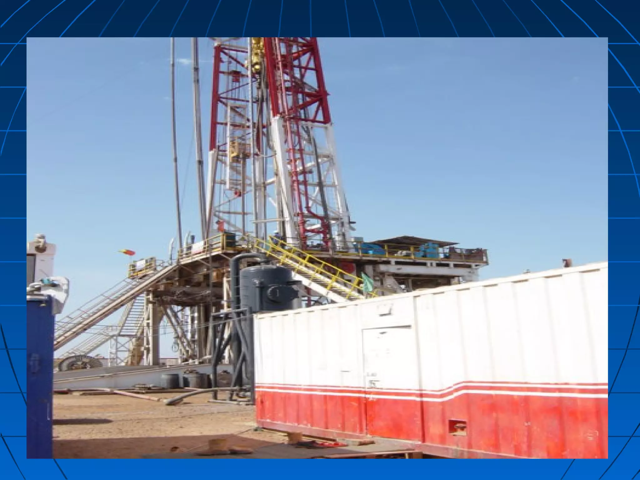
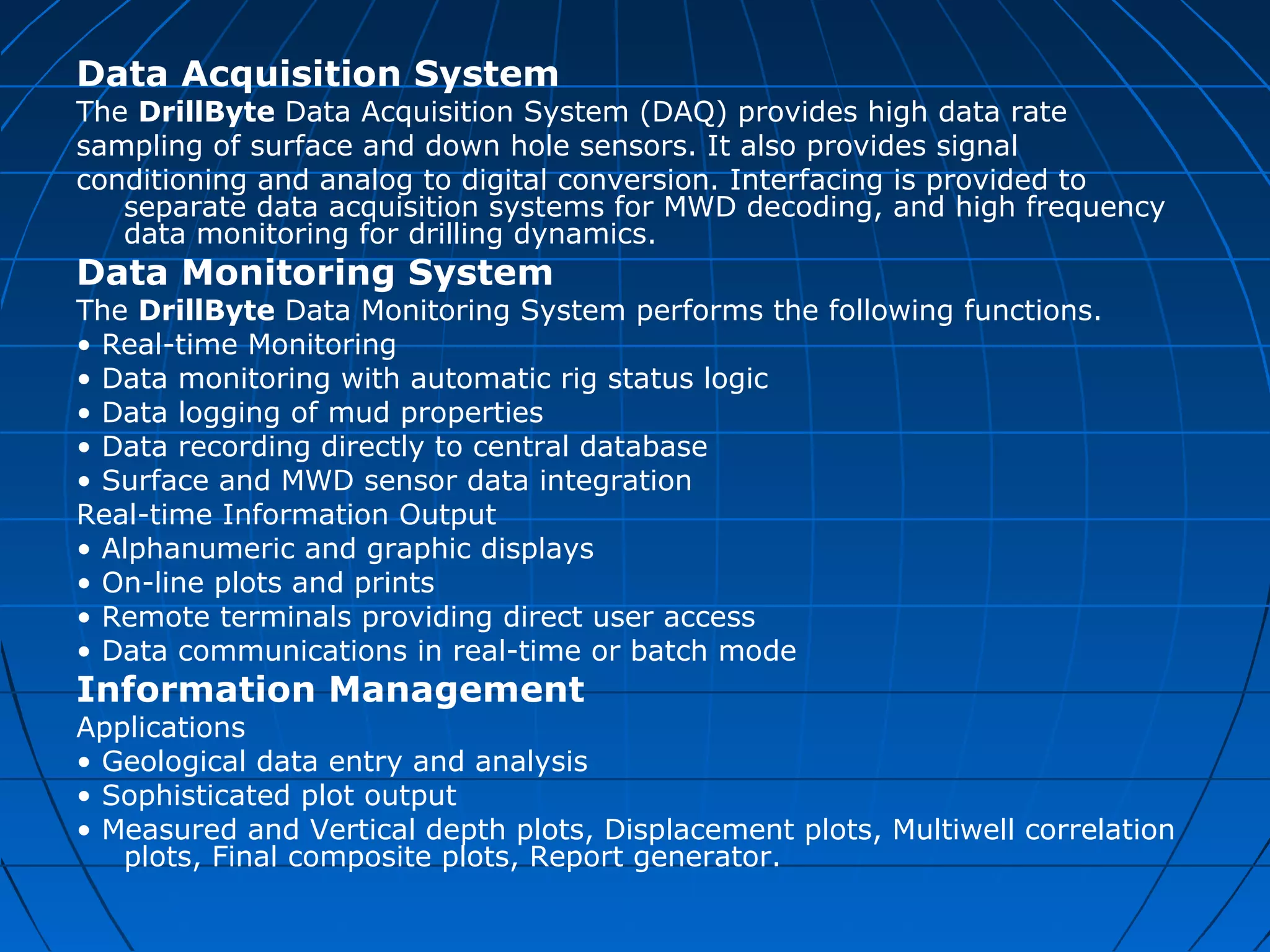
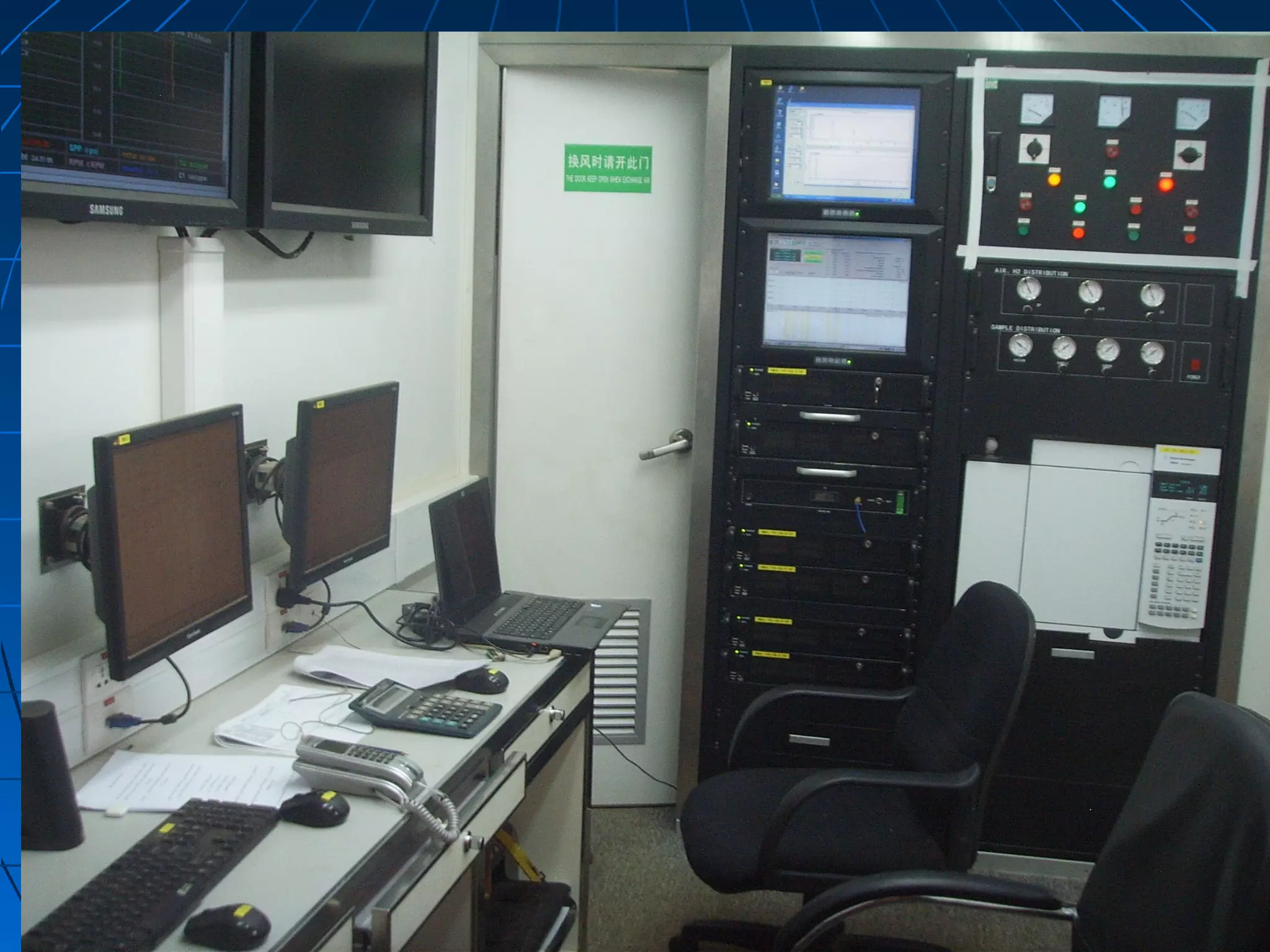
THE GOAL of topic research of MUD LOGGING as bellow:
Primary objective is delineating hydrocarbon (shows & gas), necessary service also that to introduce high qualitatively and quantitatively obtains data from drilling as reference guide, and makes observations of drilled rocks, drilling fluids and drilling parameters in order to formulate and display concepts of the optional, the mud logging unit is the information data base on the rig site to serve both exploration and drilling program.
THE GOAL of research topic to explore the MUD LOGGING as bellow:
Primary objective is delineating hydrocarbon (shows & gas), necessary service also that to introduce high qualitatively and quantitatively obtains data from drilling as reference guide, and makes observations of drilled rocks, drilling fluids and drilling parameters in order to formulate and display concepts of the optional, the mud logging unit is the information data base on the rig site to serve both exploration and drilling program.
The fourth presentation of a series of presentations on Operations Geology. Very basic, just to introduce beginners to operations geology. I hope the end users will find this and the following presentations very helpful.
The objective of this project is to investigate the measurement methods while drilling a well and perform a general assessment and comparison on the methods.
The presentation highlights the root causes of major drilling issues such as formation pressure uncertainty, subsurface feature like mud volcanoes, major fault, poor well planning & etc. Then it elaborates on consequences of all above on examples of wellbore instability, sticking, gumbo & so on.
Seismic data Interpretation On Dhodak field PakistanJamal Ahmad
I (Jamal Ahmad) presented this on 21 Feb, 2009 to defend my M.Phil dissertation in Geophysics at QAU, Islamabad, Pakistan. For more information about this, you may contact me directly at jamal.qau@gmail.com.
Our Porosity & permeability analysis product is based on the unique advantages of the Nuclear Magnetic Resonance (NMR) technique. Using permanent magnetic fields and electromagnetic energy of specific frequency, the hydrogen nuclei of the formation fluids are excited. Their response provides a lithology-independent measurement of the total porosity and the pore size distribution of the rock or sediment.
Learn more in our product sheet
fjncdjbcxfknvswykbfdbkvcsibcxjvxjbcfjcfbvbcjvgbcbbcbPrediction in petroleum simulations refers to the process of forecasting and estimating various aspects of oil and gas reservoir behavior and production performance using simulation models. Petroleum simulations involve modeling and simulating the complex processes that occur in underground reservoirs, such as fluid flow, phase behavior, rock properties, and well interactions.
In the context of petroleum engineering, simulation models are used to predict and analyze key reservoir parameters and production behavior. These predictions can include:
1. Reservoir Performance: Simulation models can predict the behavior of fluids (oil, gas, and water) within the reservoir, including flow rates, pressure changes, and fluid movement. These predictions help engineers understand how the reservoir will perform over time, including factors such as production rates, recovery factors, and pressure depletion.
2. Well Performance: Simulations can predict the performance of individual wells, including productivity, pressure drawdown, and fluid compositions. This information is crucial for well planning, optimization, and decision-making related to drilling, completion, and production strategies.
3. Fluid Behavior: Simulation models can predict the behavior of hydrocarbon fluids under different reservoir conditions, such as phase behavior (vapor-liquid-gas equilibrium), fluid compositions, and fluid properties. This information is vital for understanding fluid flow, reservoir drive mechanisms, and the potential for enhanced oil recovery (EOR) techniques.
4. Reservoir Management: Simulations help in predicting the effectiveness of reservoir management strategies, such as water flooding, gas injection, or steam injection for enhanced oil recovery. Engineers can simulate different scenarios and predict their impact on reservoir performance, production rates, and ultimate recovery.
5. Uncertainty Analysis: Simulations can also incorporate uncertainty analysis to assess the range of possible outcomes and quantify the associated risks. By considering uncertainties in parameters such as reservoir properties or production data, engineers can generate probabilistic predictions that provide insights into the range of potential outcomes.
Overall, prediction in petroleum simulations plays a crucial role in reservoir characterization, field development planning, production optimization, and decision-making in the oil and gas industry. It helps engineers and decision-makers understand reservoir behavior, evaluate different strategies, and make informed decisions to maximize hydrocarbon recovery and optimize production.define about prediction in simulationsPrediction in simulations refers to the process of estimating or forecasting the future behavior or outcomes of a system based on its current state and known dynamics. Simulations are often used to model complex systems, such as physical phenomena, economic systems, or
MineExcellence Drilling a cloud and mobile-based Platform to store, manage, document and retrieve drill related information. It may be related to …
• Daily Electronic Plod Reports
• Pre-Start Checklist
• Drill Logs
• Basic Payroll
• Invoicing
• Asset Management
Optimize your drilling operations by easy to use technology – It helps increase visibility and efficiency of all aspects of your drilling operations.
Web and mobile based data platform for key decision-making
Increasing the productivity of the companies providing an end-to-end solution across all or part of the entire drilling operation
Suitable for blast hole, exploration, geotechnical, water-well, and oil & gas drilling
A very motivated and experience Geologist in oil and gas industry. Senior Mud Logging Data Engineer since 2003; and Wellsite Geologist & Geo-Pressure Predict Engineer since 2010. Most of experienced as one man Offshore Wellsite Geologist in exploration well with high pressure and high temperature, and some horizontal production wells with very thin and critical target.
Good skills of persuading and communicating with much kind of people, especially of dealing with problem, job deadline due. Capable of working very hard, under pressure and independently.
The file discuss many topics of well logging
01 Introduction
02 Drilling fluid invasion
03 Resistivity & ARCHIE Equations
04 SP
05 resistivity log
06 gamma ray log
07 sonic log
08 density log
09 neutron log
10 litho density
11 tdt
12 plt
Abnormal pressure Zones
caliper log
Notes on shale and clay mineral
Adoption of the applied surface-backpressure types of managed pressure drilling (MPD) technologies in deepwater have mainly involved the use of a rotating control device (RCD). The RCD creates a closed drilling system in which the flow out of the well is diverted towards an automated MPD choke manifold (with a high-resolution mass flow meter) that aside from regulating backpressure also increases sensitivity and reduces reaction time to kicks, losses, and other unwanted drilling events. This integration of MPD equipment into floating drilling rigs to provide them with MPD capabilities, including the capacity to perform pressurized mud cap drilling (PMCD) and riser gas mitigation (RGM), has produced improvements not only in drillability and efficiency, but most importantly in process safety. Case histories on how MPD has performed will be presented on the following: • allowed drilling to reach target depth in rank wildcat deepwater wells that have formations prone to severe circulation losses and narrow mud weight windows; • increased drilling efficiency by minimizing non-productive time associated with downhole pressure-related problems and by allowing for the setting of deeper casing seats; • enhanced operational and process safety by allowing for immediate detection of kicks, losses and other critical downhole events. • provided riser gas mitigation capabilities that can detect a gas influx once it enters the drilling fluid stream, and not after it has already broken out above the rig blow-out preventers (BOPs).
Sharpen existing tools or get a new toolbox? Contemporary cluster initiatives...Orkestra
UIIN Conference, Madrid, 27-29 May 2024
James Wilson, Orkestra and Deusto Business School
Emily Wise, Lund University
Madeline Smith, The Glasgow School of Art
Have you ever wondered how search works while visiting an e-commerce site, internal website, or searching through other types of online resources? Look no further than this informative session on the ways that taxonomies help end-users navigate the internet! Hear from taxonomists and other information professionals who have first-hand experience creating and working with taxonomies that aid in navigation, search, and discovery across a range of disciplines.
This presentation, created by Syed Faiz ul Hassan, explores the profound influence of media on public perception and behavior. It delves into the evolution of media from oral traditions to modern digital and social media platforms. Key topics include the role of media in information propagation, socialization, crisis awareness, globalization, and education. The presentation also examines media influence through agenda setting, propaganda, and manipulative techniques used by advertisers and marketers. Furthermore, it highlights the impact of surveillance enabled by media technologies on personal behavior and preferences. Through this comprehensive overview, the presentation aims to shed light on how media shapes collective consciousness and public opinion.
Acorn Recovery: Restore IT infra within minutesIP ServerOne
Introducing Acorn Recovery as a Service, a simple, fast, and secure managed disaster recovery (DRaaS) by IP ServerOne. A DR solution that helps restore your IT infra within minutes.
0x01 - Newton's Third Law: Static vs. Dynamic AbusersOWASP Beja
f you offer a service on the web, odds are that someone will abuse it. Be it an API, a SaaS, a PaaS, or even a static website, someone somewhere will try to figure out a way to use it to their own needs. In this talk we'll compare measures that are effective against static attackers and how to battle a dynamic attacker who adapts to your counter-measures.
About the Speaker
===============
Diogo Sousa, Engineering Manager @ Canonical
An opinionated individual with an interest in cryptography and its intersection with secure software development.
This presentation by Morris Kleiner (University of Minnesota), was made during the discussion “Competition and Regulation in Professions and Occupations” held at the Working Party No. 2 on Competition and Regulation on 10 June 2024. More papers and presentations on the topic can be found out at oe.cd/crps.
This presentation was uploaded with the author’s consent.
Competition and Regulation in Professional Services – KLEINER – June 2024 OEC...
Presentation1 practical purposes of mud logging
1. PRACTICAL PURPOSES OFPRACTICAL PURPOSES OF
MUD LOGGINGMUD LOGGING
By: Elharith MohamedBy: Elharith Mohamed
EleasilyEleasily
CHINA NATIONALCHINA NATIONAL
LOGGING CORPORATIONLOGGING CORPORATION
2. MUD LOGGING DEFINITIONMUD LOGGING DEFINITION::
MUD LOGGING is serve to providesMUD LOGGING is serve to provides
monitor well site activities and tomonitor well site activities and to
analyze the drilling cuttings for lithologyanalyze the drilling cuttings for lithology
identification and hydrocarbonidentification and hydrocarbon
evaluation. The resulting plots of thoseevaluation. The resulting plots of those
activities and cutting analysis versusactivities and cutting analysis versus
depth is termed a MUD LOG.depth is termed a MUD LOG.
3. Mud logging:Mud logging:
IIs a useful evaluation technique thats a useful evaluation technique that
has developed since the advent ofhas developed since the advent of
rotary drilling in the 1920s. Sincerotary drilling in the 1920s. Since
mud circulates constantly duringmud circulates constantly during
drilling, mud logging can providedrilling, mud logging can provide
information on a continuousinformation on a continuous
formation evaluation.formation evaluation.
4. THE GOAL OF MUD LOGGING?THE GOAL OF MUD LOGGING?
- Primary objective is delineatingPrimary objective is delineating
hydrocarbon (shows & gas), necessaryhydrocarbon (shows & gas), necessary
service also that to introduce highservice also that to introduce high
qualitatively and quantitatively obtainsqualitatively and quantitatively obtains
data from drilling as reference guide, anddata from drilling as reference guide, and
makes observations of drilled rocks,makes observations of drilled rocks,
drilling fluids and drilling parameters indrilling fluids and drilling parameters in
order to formulate and display concepts oforder to formulate and display concepts of
the optional, the mud logging unit is thethe optional, the mud logging unit is the
information data base on the rig site toinformation data base on the rig site to
serve both exploration and drillingserve both exploration and drilling
program.program.
5. Purpose MUD LOGGINGPurpose MUD LOGGING involves:involves:
- Observing drilling efficiency,Observing drilling efficiency,
depth and ROP, lag timedepth and ROP, lag time
determination.determination.
- Comprehensive formationComprehensive formation
evaluation,evaluation, cuttings samplingcuttings sampling
and lithological description.and lithological description.
-- Gas sampling and analysis.Gas sampling and analysis.
- Apply drilling safety.- Apply drilling safety.
6. The mud logging unit crew should beThe mud logging unit crew should be
able to provide:able to provide:
_ Personnel trained in the interpretation of all_ Personnel trained in the interpretation of all
derived data, capable of providing interpretationderived data, capable of providing interpretation
and observations to the well site geologist and toand observations to the well site geologist and to
the company man.the company man.
_ Monitor drilling parameters and abnormal events._ Monitor drilling parameters and abnormal events.
_ Monitor mud properties and the pit volumes._ Monitor mud properties and the pit volumes.
_ Monitor gas and its components using FID,_ Monitor gas and its components using FID,
Chromatograph-Integrator, CO2and H2S.Chromatograph-Integrator, CO2and H2S.
_ Data processing, storage, display and_ Data processing, storage, display and
transmission to oil company in town.transmission to oil company in town.
_ Print out, store and display mud logs, pressure_ Print out, store and display mud logs, pressure
logs and other logs needed at the well site.logs and other logs needed at the well site.
_ Perform specialized tests and analyses._ Perform specialized tests and analyses.
7. MUD LOGGING UNITSMUD LOGGING UNITS
Common types of units:Common types of units:
Drillbyte mud logging unit.Drillbyte mud logging unit.
Advantage mud logging unit.Advantage mud logging unit.
8.
9. Type one:Type one: DrillByte system is Baker
Hughes INTEQ’s wellsite geological and
engineering information management
service.
A totally integrated information service is an
essential factor in successfully locating
hydrocarbons while drilling exploration and
development wells safely and
economically. The provision of useful
information in a timely manner requires
the DrillByte system approach to data
management through a central integrated
database which can store all the
engineering and geological information.
10. Information output from DrillByte is
displayed in a format that is easily
interpreted so operational decisions can be
made correctly and quickly.
DrillByte uses a high-resolution graphic
user-interface (GUI) to simplify operation
of the system for local and remote users.
This GUI enables the users to concentrate
on interpretation and evaluation.
Advanced, but user friendly engineering and
geological applications are provided with
the DrillByte service for processing the
data to enhance the evaluation process.
11. DrillByte OverviewDrillByte Overview
DrillByte uses a multi-tasking, multi-user system,
with a high resolution graphic interface, and runs
on a client/server architecture.
DrillByte is divided into five major components:
• Data Acquisition
• Data Monitoring
• Drilling Dynamics Monitoring
• Information Management
• MWD Processing
12. Data Acquisition System
The DrillByte Data Acquisition System (DAQ) provides high data rate
sampling of surface and down hole sensors. It also provides signal
conditioning and analog to digital conversion. Interfacing is provided to
separate data acquisition systems for MWD decoding, and high frequency
data monitoring for drilling dynamics.
Data Monitoring System
The DrillByte Data Monitoring System performs the following functions.
• Real-time Monitoring
• Data monitoring with automatic rig status logic
• Data logging of mud properties
• Data recording directly to central database
• Surface and MWD sensor data integration
Real-time Information Output
• Alphanumeric and graphic displays
• On-line plots and prints
• Remote terminals providing direct user access
• Data communications in real-time or batch mode
Information Management
Applications
• Geological data entry and analysis
• Sophisticated plot output
• Measured and Vertical depth plots, Displacement plots, Multiwell correlation
plots, Final composite plots, Report generator.
13. Engineering Assistance Programs
• Mud hydraulics analysis
• Bit optimization
• Well control
• Directional survey analysis
• Torque and Drag analysis
• Formation Pressure analysis
MWD Processing
• Real time data processing
• Tool communications
• Memory data processing
• Log presentation
14. Type two:Type two: Advantage mud loggingAdvantage mud logging
unitunit
The main service feature is:The main service feature is:Minimum human interference:
- Random errors minimized, best accuracy.
More time for interpretation & More time for
monitor.
Fully computerized service:
- High speed data processing (possible
data transmission)
Better presentation of data & On time
decision making.
Best possible equipment design:
Maximum possible accuracy.
Intrinsic safety:
- Safety environment
- Safety equipment & Efficient warning
system.
15. The cabin should have been pre configured, the
following is introduce of computers functions:
ADV1 : Real-time. machine which will run all data
acquisition, real-time processing and data storage-
Dlogger. This machine is to be left to these core programs
and not used for reports or pit monitoring.
ADV2 : Monitoring & Rig link Sever. machine which the
Data engineer will do pit monitoring with RtPlot and Riglink
IE6. He can also do reports and make logs with case.
ADV3 : Mud logger. machine is for inputting lithologies
into GEO and producing logs with CASE. Can also run IE6
rig link or RtPlot for monitoring the well.
ADV4 : Database. Machine is set aside purely to run
Server and Riglink server applications. Nothing including
IE6 should be run.
ADV5 : Displays. computer for replicating the (VGA)
display to the drill floor, tool pusher and geologist and
company man via Black box repeaters or VGA splitters.
16. As real time monitoring system theAs real time monitoring system the
units is renewal and update timely,units is renewal and update timely,
two types of units connecting directlytwo types of units connecting directly
to office client and department officeto office client and department office
by (RDT) system real data transfer.by (RDT) system real data transfer.
The drilling data convert while drillingThe drilling data convert while drilling
by electrical sensors locate in rig partby electrical sensors locate in rig part
and connected on unit, the unitand connected on unit, the unit
system is responsible to analyzesystem is responsible to analyze
sensors information to parameters assensors information to parameters as
two type digital number and curves.two type digital number and curves.
19. Sensors functionSensors function
1.1. Block height: Monitor the position of the traveling block,Block height: Monitor the position of the traveling block,
operate as ROP indicator Measure depth, locate in theoperate as ROP indicator Measure depth, locate in the
draw work.draw work.
2.2. Hook load: Measure the tension on the cable from drawHook load: Measure the tension on the cable from draw
work, location: deadline.work, location: deadline.
3. SPP: the system measure the pressure of mud on the
standpipe, locate in stand pipe pressure.
4. Rotary torqueRotary torque measure torque being applied to the drill string,
location: Rotary table or top drive motor power cable.
5. Pit volumePit volume measure the ultrasonic transmitter time to
calculate the mud in the tank, location: mud pit.
6. Rotary table system: technical data: Sensor type: Proximity
switch, measure range: 0 ~ 300 rpm/spm.
20. Sensors function continueSensors function continue
7.7. Mud temperature system:Mud temperature system: use resistance change (Pt) to
measure mud temperature.
8. Mud Density Measuring System:Mud Density Measuring System: the system use twin remote
diaphragm sensors to measures mud density in and out,
location: In-section pit, Out-Shale shake.
9. Mud Conductivity Measuring System:Mud Conductivity Measuring System: a probe type sensor is used
to measure an induced current in the mud loop, location:
In-section pit, Out-Shale shake.
10. Mud flow out systemMud flow out system : a variable position paddle is used to
measure the amount of mud in the flow line quantity,
location: flow line.
11. H2S sensor:H2S sensor: technical Data: Sensor type: electrochemical
measure range: 0 ~ 100 ppm, Signal output: Computer,
alarms
Location: Rig floor, shale shaker, caller, mud logging
unit.
21. Gas systemGas system
Major purpose data supplied by mud loggingMajor purpose data supplied by mud logging
is gas data, a mud logging consist of gasis gas data, a mud logging consist of gas
system to determine gas data aftersystem to determine gas data after
complex measurement, gas systemcomplex measurement, gas system
involve:involve:
_ Chromatograph._ Chromatograph.
_ Degasser._ Degasser.
_ Hydrogen._ Hydrogen.
_ Air compressor._ Air compressor.
_ FID component._ FID component.
_ CO2 sensor._ CO2 sensor.
23. MUDLOGGING PERSONNELMUDLOGGING PERSONNEL
DUTIES & RESPONSIBILITIESDUTIES & RESPONSIBILITIES
DATA ENGINEER( Unit leader).DATA ENGINEER( Unit leader).
The Unit leader is the senior mud logging engineerThe Unit leader is the senior mud logging engineer
on the location. He has primary responsibility foron the location. He has primary responsibility for
the maintenance, management and provision ofthe maintenance, management and provision of
service by the logging unit, its equipment andservice by the logging unit, its equipment and
personnel to the client.personnel to the client.
Mud Logger.Mud Logger.
He is responsible for the maintenance and correctHe is responsible for the maintenance and correct
operation of the equipment. He is responsible foroperation of the equipment. He is responsible for
the collection and presentation of the informationthe collection and presentation of the information
monitored in accordance with company standardmonitored in accordance with company standard
procedures and customer requirements to ensureprocedures and customer requirements to ensure
a high quality service.a high quality service.
25. Purpose of sample description:Purpose of sample description:
Sample describe to observe :Sample describe to observe :
_ Lithology._ Lithology.
_ Hydrocarbon shows._ Hydrocarbon shows.
_ Porosity._ Porosity.
_ Other geological properties._ Other geological properties.
26.
27. The materials supplies for proper sampleThe materials supplies for proper sample
examination at the well site is updateexamination at the well site is update
timely, below are some additionaltimely, below are some additional
comments on the equipments and suppliescomments on the equipments and supplies
to ensure they acceptable standards.to ensure they acceptable standards.
BINOCULAR MICROSCOPE:BINOCULAR MICROSCOPE:
To observed cutting samples type andTo observed cutting samples type and
distributions of grain include accessoriesdistributions of grain include accessories
minerals, binocular magnification rangeminerals, binocular magnification range
from 5x to 30x, accordingly must havefrom 5x to 30x, accordingly must have
grain size comparator to determine graingrain size comparator to determine grain
size.size.
28.
29. FLUORSCOPE:FLUORSCOPE:
This is ULTRAVIALOT light box anThis is ULTRAVIALOT light box an
important part for oil on cuttingimportant part for oil on cutting
detector, the 3600A wave length isdetector, the 3600A wave length is
standard for UV inspection, with thestandard for UV inspection, with the
fluoroscope an organic solvent usedfluoroscope an organic solvent used
to distinguish between hydrocarbonto distinguish between hydrocarbon
and mineral fluorescence.and mineral fluorescence.
31. Solvent Cut TestSolvent Cut Test
Chemicals Used For The Solvent CutChemicals Used For The Solvent Cut
Test:Test:
The solvent cut test is useful inThe solvent cut test is useful in
determining the quality of the show.determining the quality of the show.
You can use different solvents forYou can use different solvents for
this test:this test:
35. CHEMICAL ACID:CHEMICAL ACID:
A dilute hydrochloric acid (10%) isA dilute hydrochloric acid (10%) is
recommended when examiningrecommended when examining
samples. A carbonates stainingsamples. A carbonates staining
solution of Alizarin red should besolution of Alizarin red should be
available when drilling carbonates,available when drilling carbonates,
Phenolphthalein can be use toPhenolphthalein can be use to
detect casing cement.detect casing cement.
37. CUTTINGCUTTING DESCRIPTIONS:DESCRIPTIONS:
Order Of Written Descriptions areOrder Of Written Descriptions are
written using abbreviations. Thewritten using abbreviations. The
AAPG standard set of abbreviationsAAPG standard set of abbreviations
are normally used, but some clientsare normally used, but some clients
would require that their own set ofwould require that their own set of
abbreviations.abbreviations.
38. ATTENTION: THE GUIDE LINE DESCRIPITONATTENTION: THE GUIDE LINE DESCRIPITON
MUST FOLLOW:MUST FOLLOW:
Classification, color, hardnessin duration,Classification, color, hardnessin duration,
grain size, grain shape, sorting, luster,grain size, grain shape, sorting, luster,
cement matrix, visual porosity,cement matrix, visual porosity,
accessories, hydrocarbon content.accessories, hydrocarbon content.
Examples:Examples:
Sst:Sst: trnsl - trnsp, lt gy, off wh, uncons, vf - crs gr,trnsl - trnsp, lt gy, off wh, uncons, vf - crs gr,
subang - subrnd, mod w srtd, qtz, arg mtx, mica,subang - subrnd, mod w srtd, qtz, arg mtx, mica,
glau, p-fr vis por, n vis o stn, tr spt fnt yel dirglau, p-fr vis por, n vis o stn, tr spt fnt yel dir
fluor, tr slow strmg fnt mky wh cut fluor, no visfluor, tr slow strmg fnt mky wh cut fluor, no vis
resd o.resd o.
CLYST:CLYST: lt gy -med gy, occ dk gy, sbblky -blky, modlt gy -med gy, occ dk gy, sbblky -blky, mod
hd, mic mica, sl calc.hd, mic mica, sl calc.
Ls:Ls: oolitic grainstone, buff- brn, med gr, mod hd,oolitic grainstone, buff- brn, med gr, mod hd,
arg, Brach, glau, gd vis por, no oil shows.arg, Brach, glau, gd vis por, no oil shows.
39. According to environmental depositionAccording to environmental deposition
formation color change, that indicateformation color change, that indicate
for formation top some time, thefor formation top some time, the
following is depositional color origins:following is depositional color origins:
_ Red and brown back to oxidizing_ Red and brown back to oxidizing
environment.environment.
_ Green and grey spouse to be_ Green and grey spouse to be
reducing environment.reducing environment.
_ dark brown possible to be source_ dark brown possible to be source
rock.rock.
_ black color indicate for anaerobic_ black color indicate for anaerobic
environment.environment.
40. Sample types:Sample types:
The several sample types is:The several sample types is:
_ Wet un wash samples._ Wet un wash samples.
_ Wash and dried samples._ Wash and dried samples.
_ Geochemical samples._ Geochemical samples.
_ Paleontological / samples ( bios rat_ Paleontological / samples ( bios rat
sample).sample).
_ Metal shavings._ Metal shavings.
_ Mud samples._ Mud samples.
41. Mud Log PresentationMud Log Presentation
A mud log in its essential form is an interpretativeA mud log in its essential form is an interpretative
tool.tool.
The production of a mud log requires consummateThe production of a mud log requires consummate
skill derived from a geological background,skill derived from a geological background,
training and field experience.training and field experience.
A mud log should contain the following track:A mud log should contain the following track:
_ ROP/WOB track._ ROP/WOB track.
_ Depth track._ Depth track.
_ Cuttings litho logy track._ Cuttings litho logy track.
_ Gas track._ Gas track.
_ Chromatography track._ Chromatography track.
43. LAG TIME OR BOTTOM UP:LAG TIME OR BOTTOM UP:
This a technique required for mud, gas orThis a technique required for mud, gas or
other materials to travel from the bottomother materials to travel from the bottom
of the hole to place at which they areof the hole to place at which they are
collected.collected.
Purpose of lag time:Purpose of lag time:
- InformationInformation’’s about litho logy and changes about litho logy and change
in facieses vs. depth interval.in facieses vs. depth interval.
- Correlation of the cutting samples and gasCorrelation of the cutting samples and gas
to the formation and depth at which theyto the formation and depth at which they
are originated.are originated.
- Geometry of the hole condition (caving orGeometry of the hole condition (caving or
tight hole).tight hole).
44.
45. LAG DEFINITIONLAG DEFINITION
Lag define asLag define as the time mud takes to travelthe time mud takes to travel
inside the hole between two specifiedinside the hole between two specified
depth points.depth points.
The time taken between the surface to theThe time taken between the surface to the
bottom of the hole is called lag down orbottom of the hole is called lag down or
Lag in.Lag in.
The time taken between the bottom of theThe time taken between the bottom of the
hole to the surface is called lag-up orhole to the surface is called lag-up or
bottoms up.bottoms up.
The surface to surface time is calledThe surface to surface time is called
Complete cycle or In/Out time.Complete cycle or In/Out time.
46. Calculate methods types:Calculate methods types:
There is two types of lag time checkThere is two types of lag time check
- Lag time check manually.Lag time check manually.
- Lag time check by computer.Lag time check by computer.
47. Lag time check by computerLag time check by computer
EQUATION:EQUATION:
Theo: lag time:Theo: lag time: lag strokelag stroke minutesminutes
total spmtotal spm
Act: lag time:Act: lag time: cycle timecycle time –– down timedown time minutesminutes
total spmtotal spm
Caving or tight hole:Caving or tight hole: Act: lag timeAct: lag time –– Theo: lag timeTheo: lag time x100x100
Theo: lag timeTheo: lag time
49. V annu. = V hole - V drl.string (OD)
DOWN TIME = V drl string (ID)/ MUD FLOW IN
MUD FLOW IN = TOTAL SPM X VOLUME/STK(PUMP OUTPUT)
VOLUME/STK = LINER((ID)/2)
2
X STK LENGTH X EV X 3 X 3.14(TRIPLEX)
LAG TIME CHECK
THEO. T. =V annu./ MUD FLOW IN
ACT. T. =CYCLE T.- DOWN TIME
CAV.(%) = (ACT. T. - THEO. T.)/THEO. T
V = L X (D/2)2
X 3.14
V drilling string =V DC + V HWDP +V DP (ID)
V drilling string = V DC + V HWDP +V DP (OD)
V hole = V csg + V open hole