Downloaded 36 times

![BONDING OF CFRP
PLATES :
Test results
Test Specimen Fbr [KN] Ybr [mm] Εbr
Specimen 1 Curing 161 70 6.61
without oscillation
Specimen 4 176 75 6.55
Curing with oscillation](https://image.slidesharecdn.com/presentationonratingstrengtheningofbridgesjntu-hydbyraghavendra-130401154604-phpapp01/75/Presentation-on-rating-strengthening-of-bridges-jntu-hyd-by-raghavendra-11-2048.jpg)


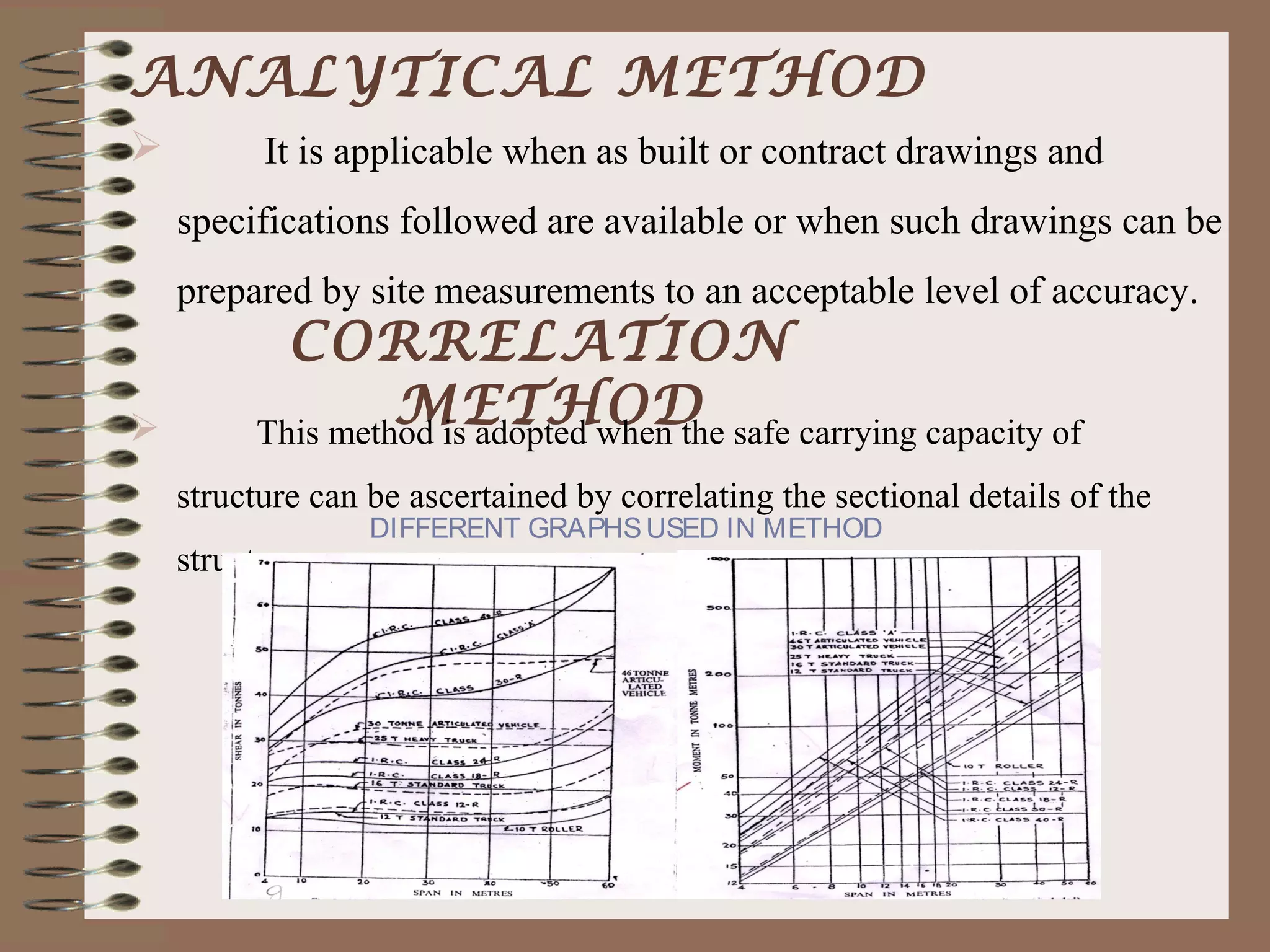
The document outlines the process and methodology for rating the safety and load-bearing capacity of bridges, detailing various rating methods such as analytical, correlation, and load test methods. It includes procedures for calculating safe axle loads, strengthening techniques, and posting restrictions to ensure bridge safety. The conclusion emphasizes the importance of proper rating to prevent accidents and supports follow-up actions like repairs or demolitions as necessary.


