Download as PDF, PPTX

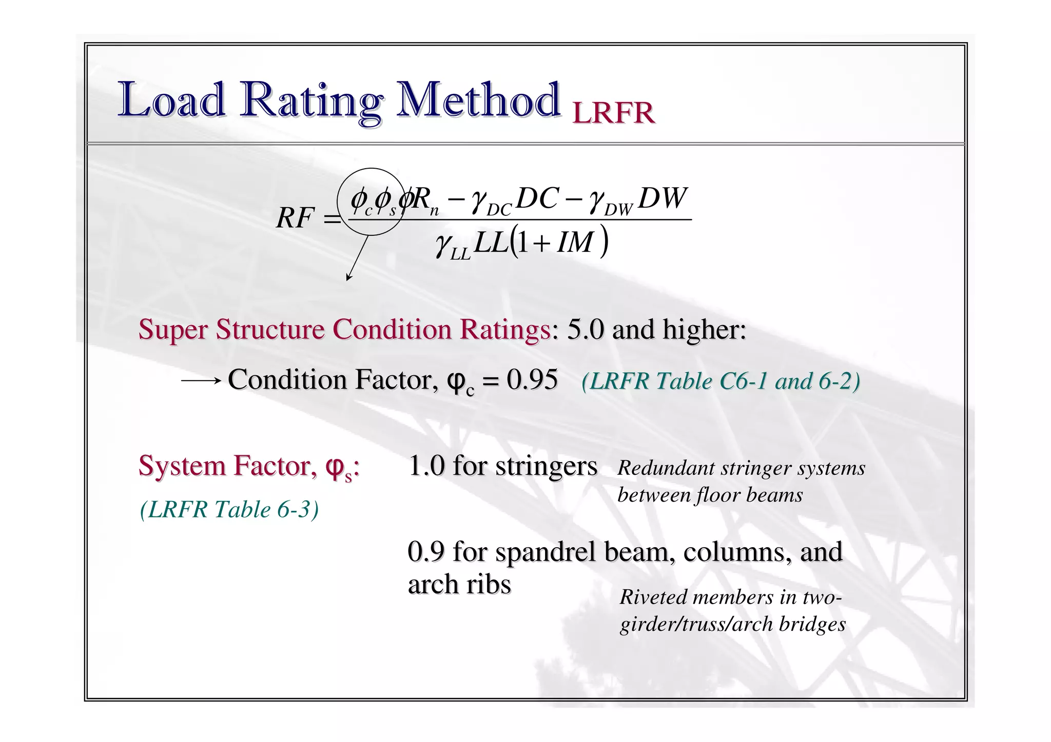
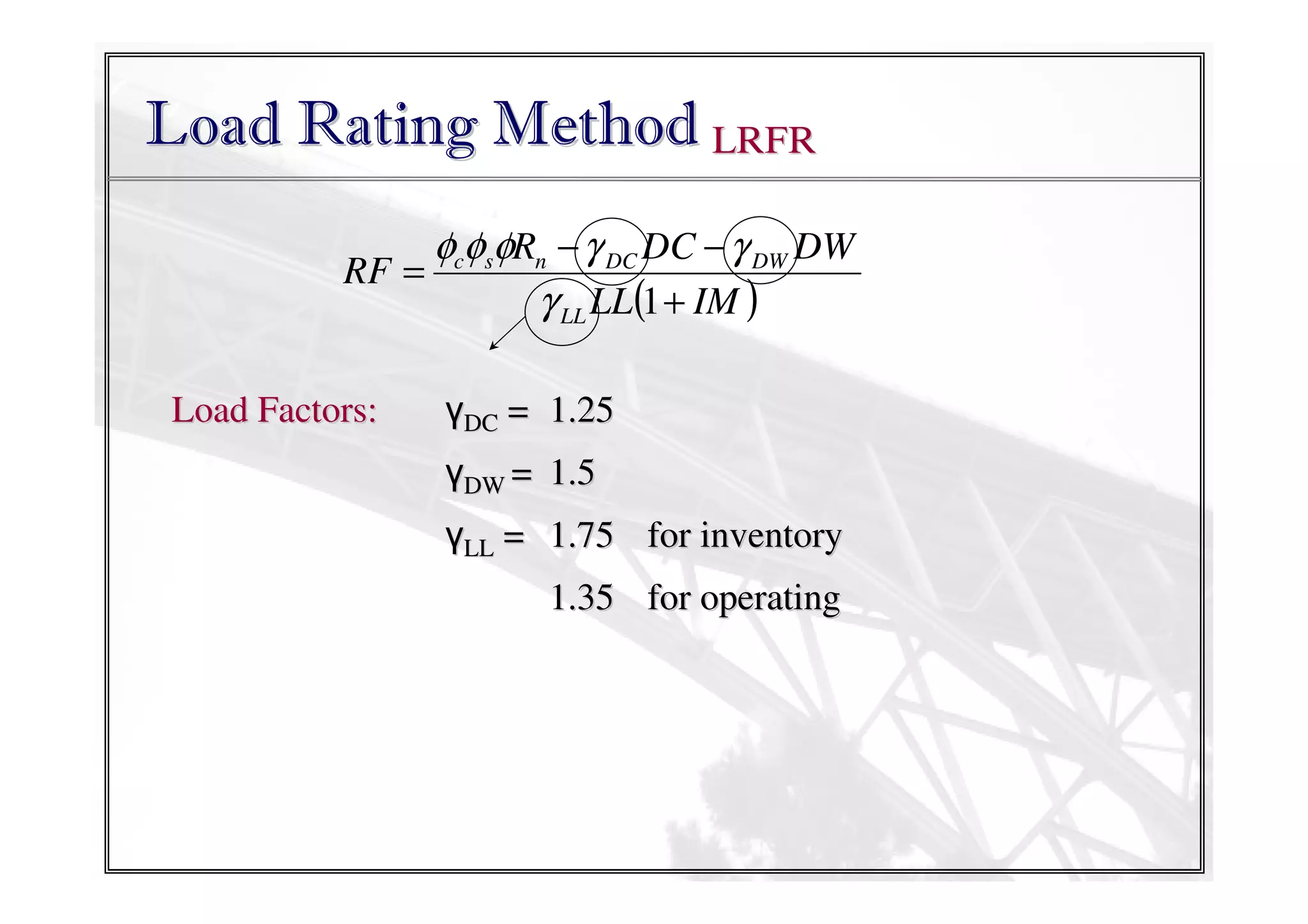
![Load Rating Method LRFR
(a) TRUCK LOADS: HS-20 and Design Tandem
8k
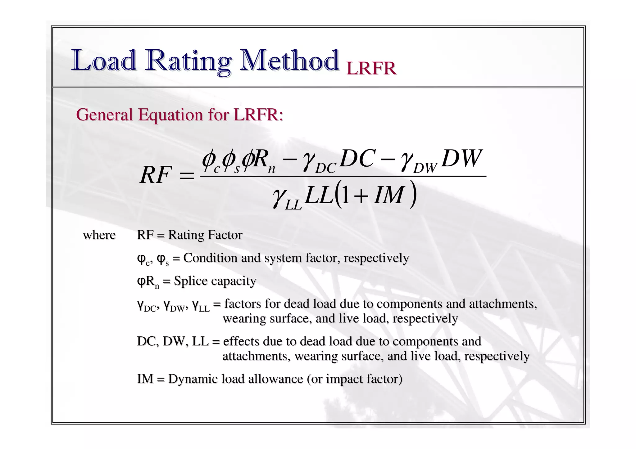
φcφsφRn − γ DC DC − γ DW DW
RF = 32k
32k
25k
γ LL LL(1 + IM )
25k
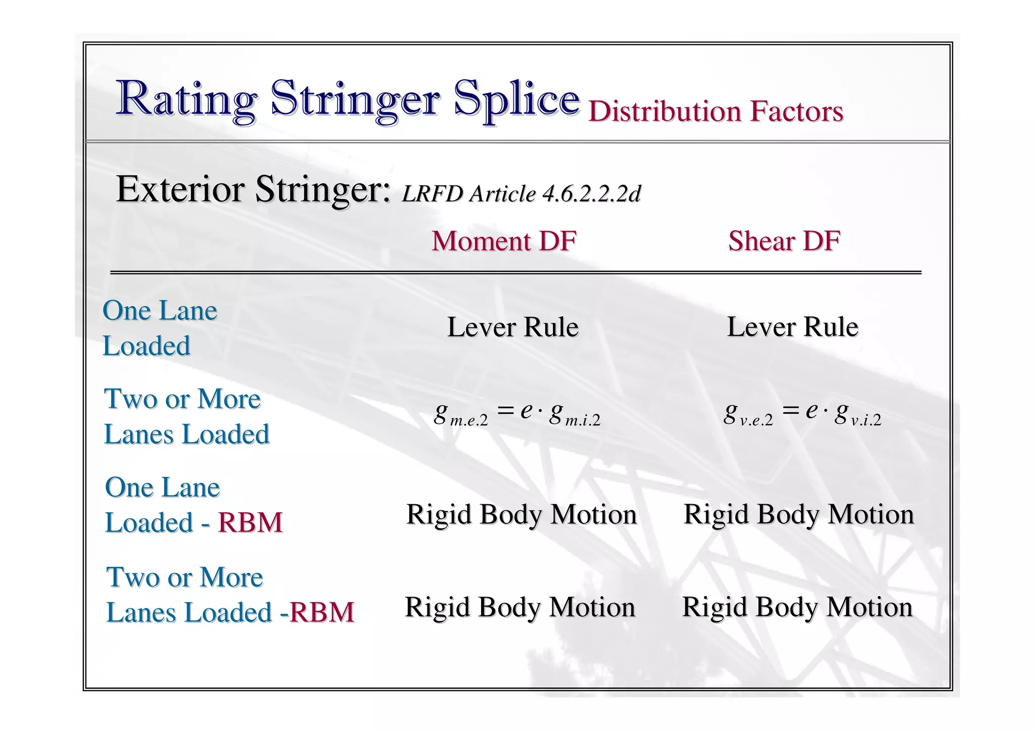
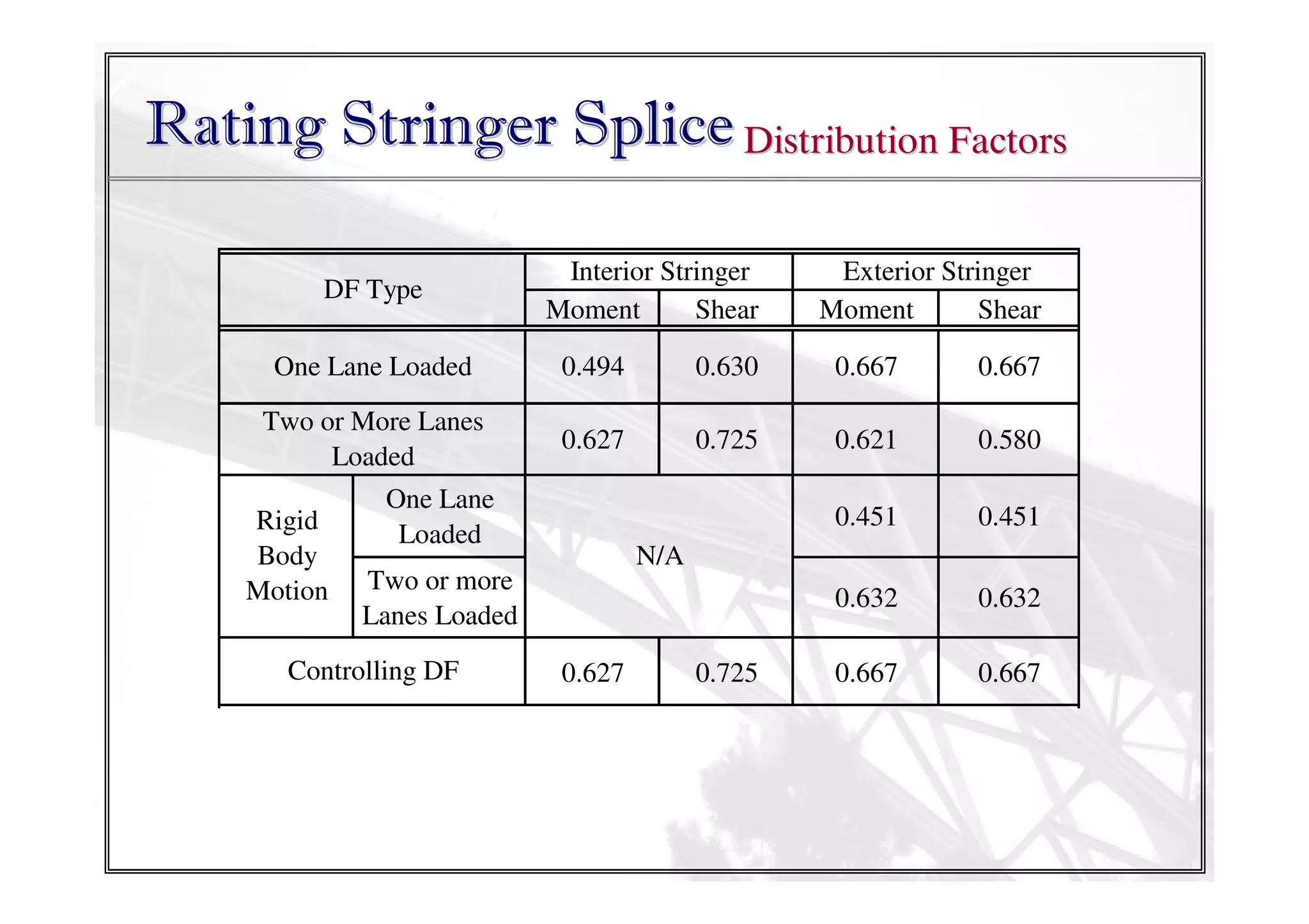
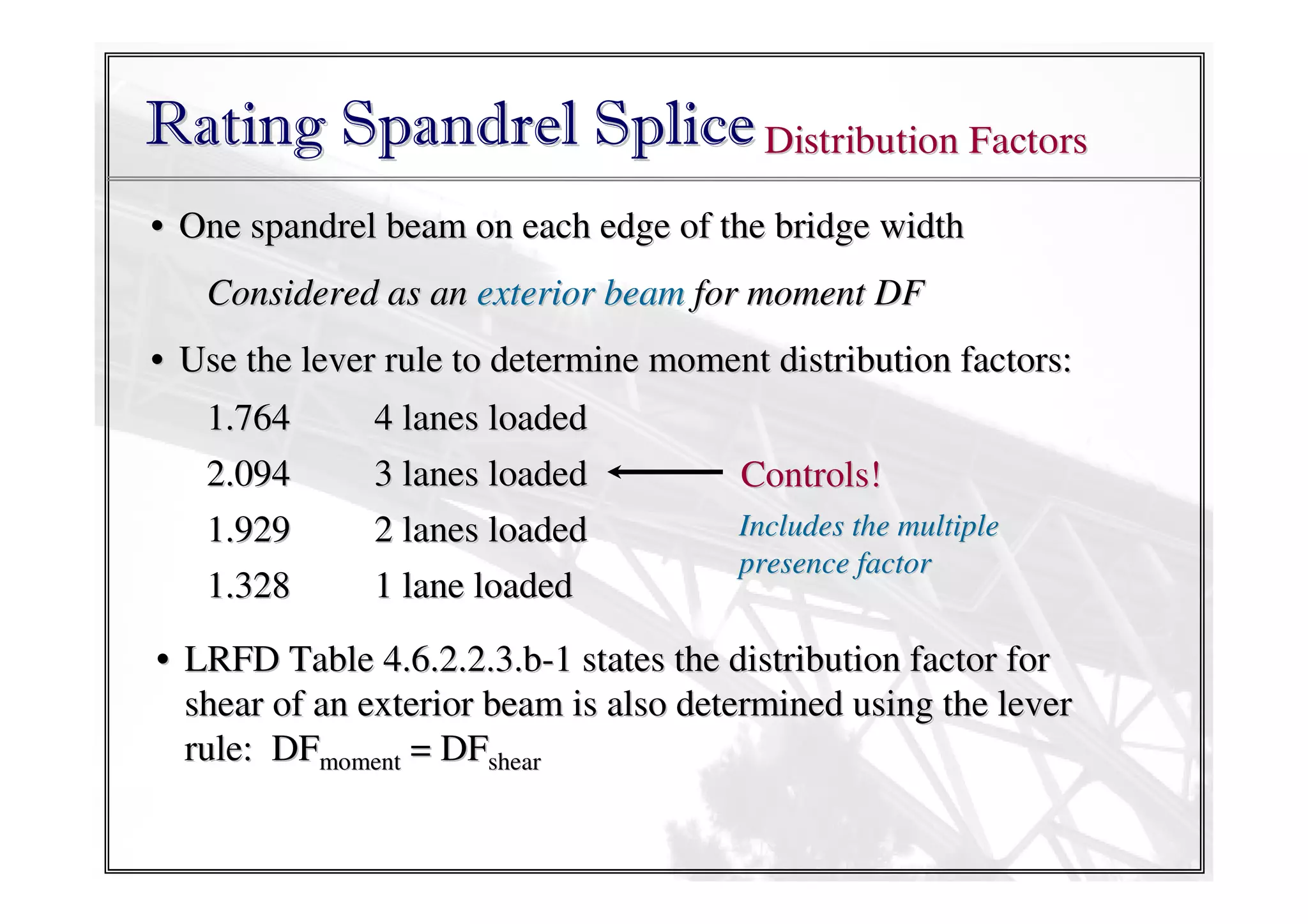
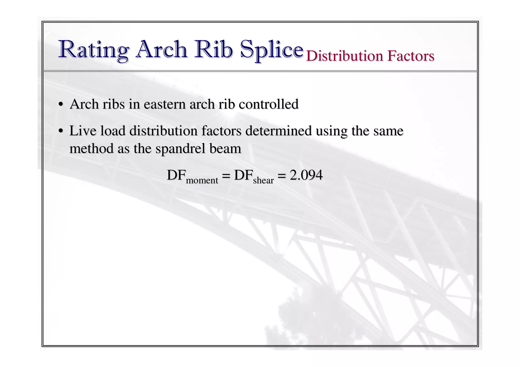
For each member, distribution factor for different force effects
must be applied: i.e., to 30moment or DFshear
4 ft
14ft
14 DF ft
Live Load Effect = γ LL DF [Lane + Design Tandem IM)]
Truck (1 + (Longitudinal)
HS-20 (Longitudinal)
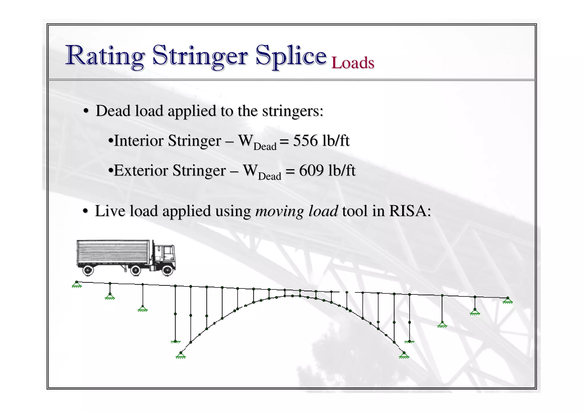
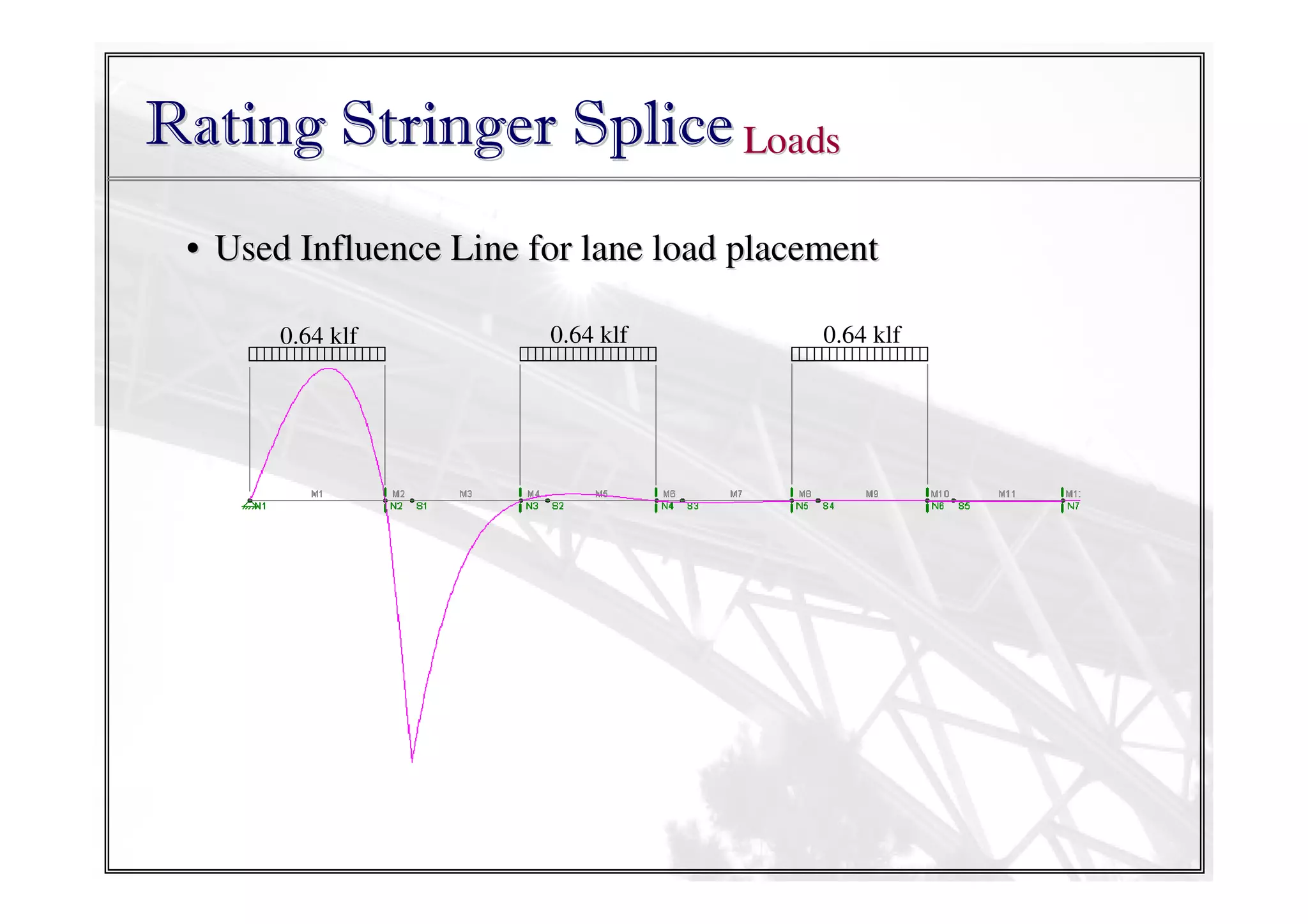
(b) LANE LOAD
Controlled by larger effect between HS-20 or Design Tandem
Lane Load = 0.64 klf](https://image.slidesharecdn.com/sapienzauniversityofrome60minpartiiconnectionsmodified-131208082842-phpapp01/75/CM-Jauregui-Sapienza-University-of-Rome-60-min-part-ii-connections-modified-12-2048.jpg)

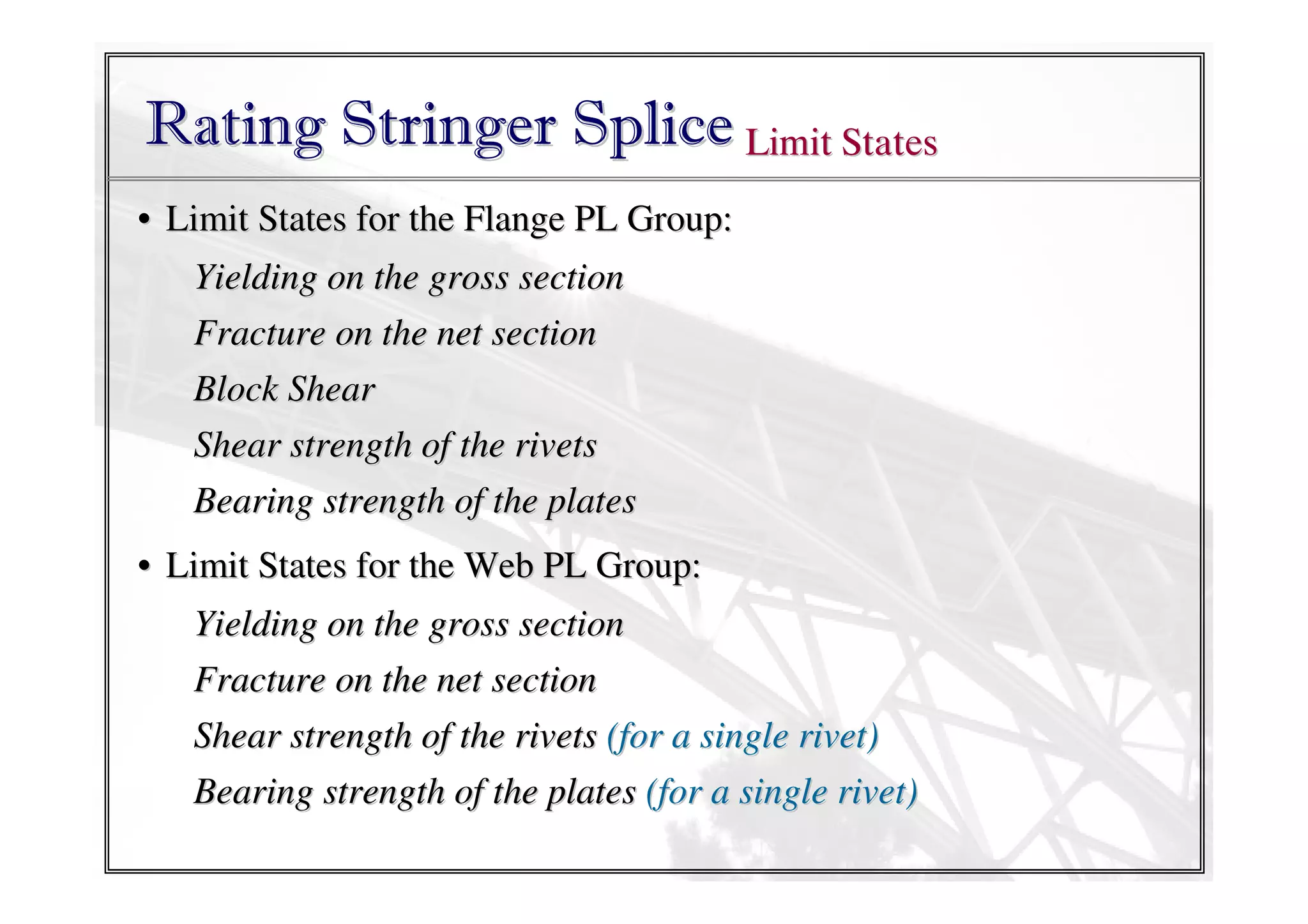


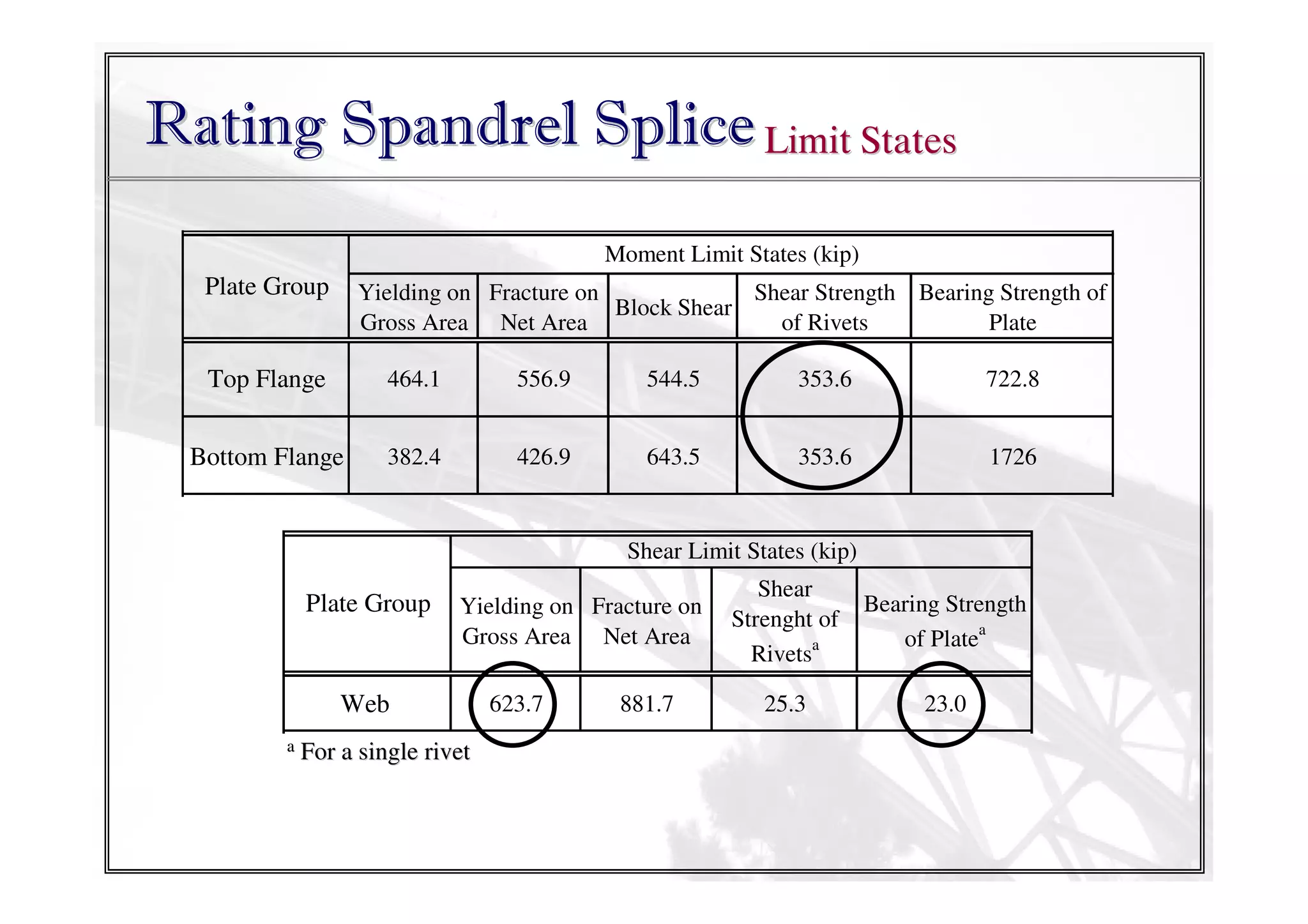

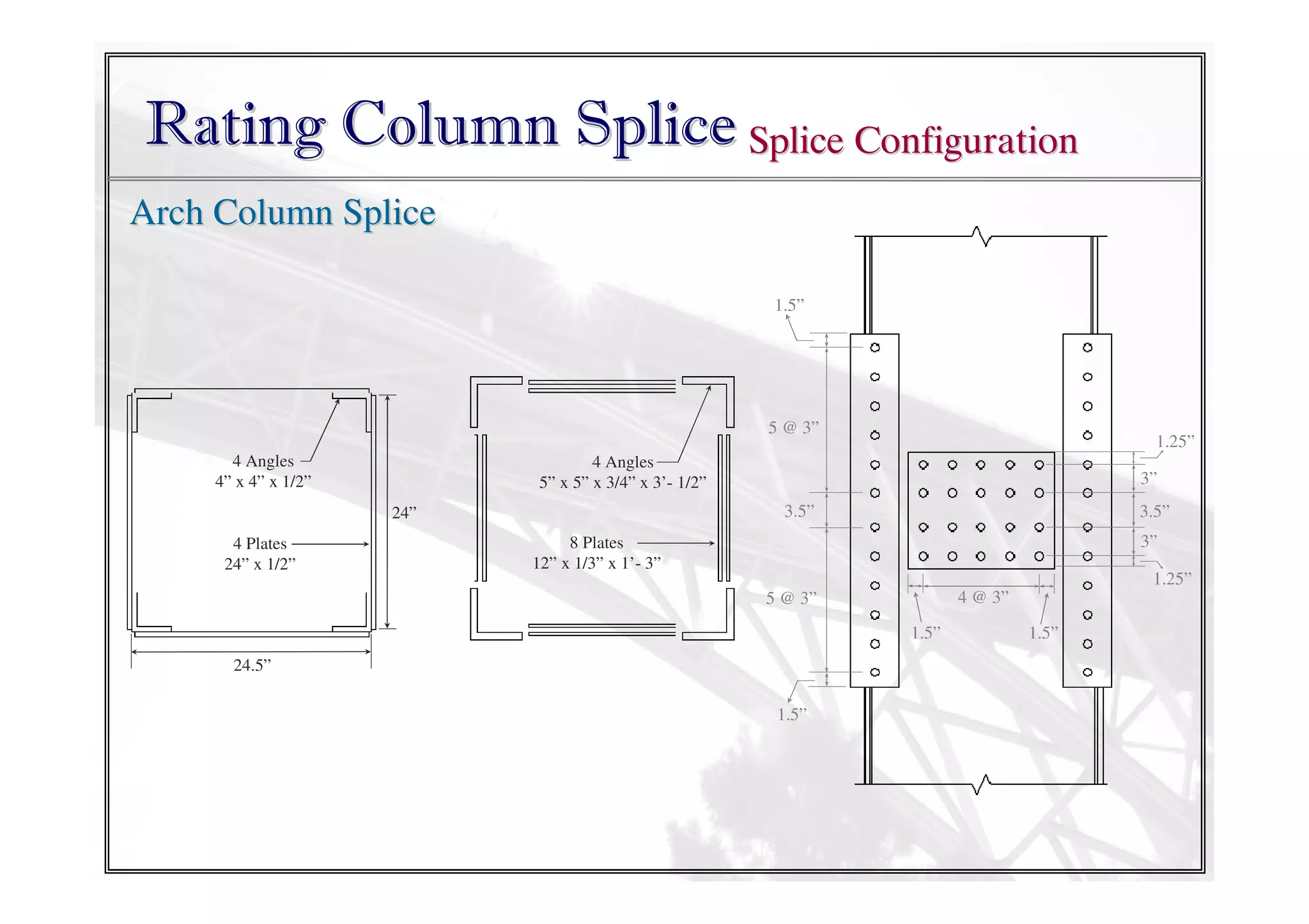
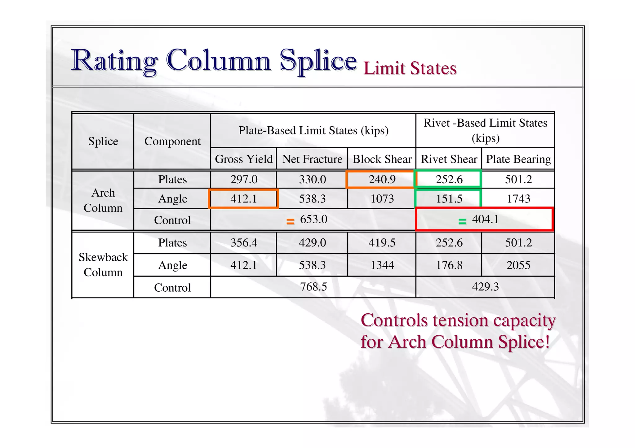
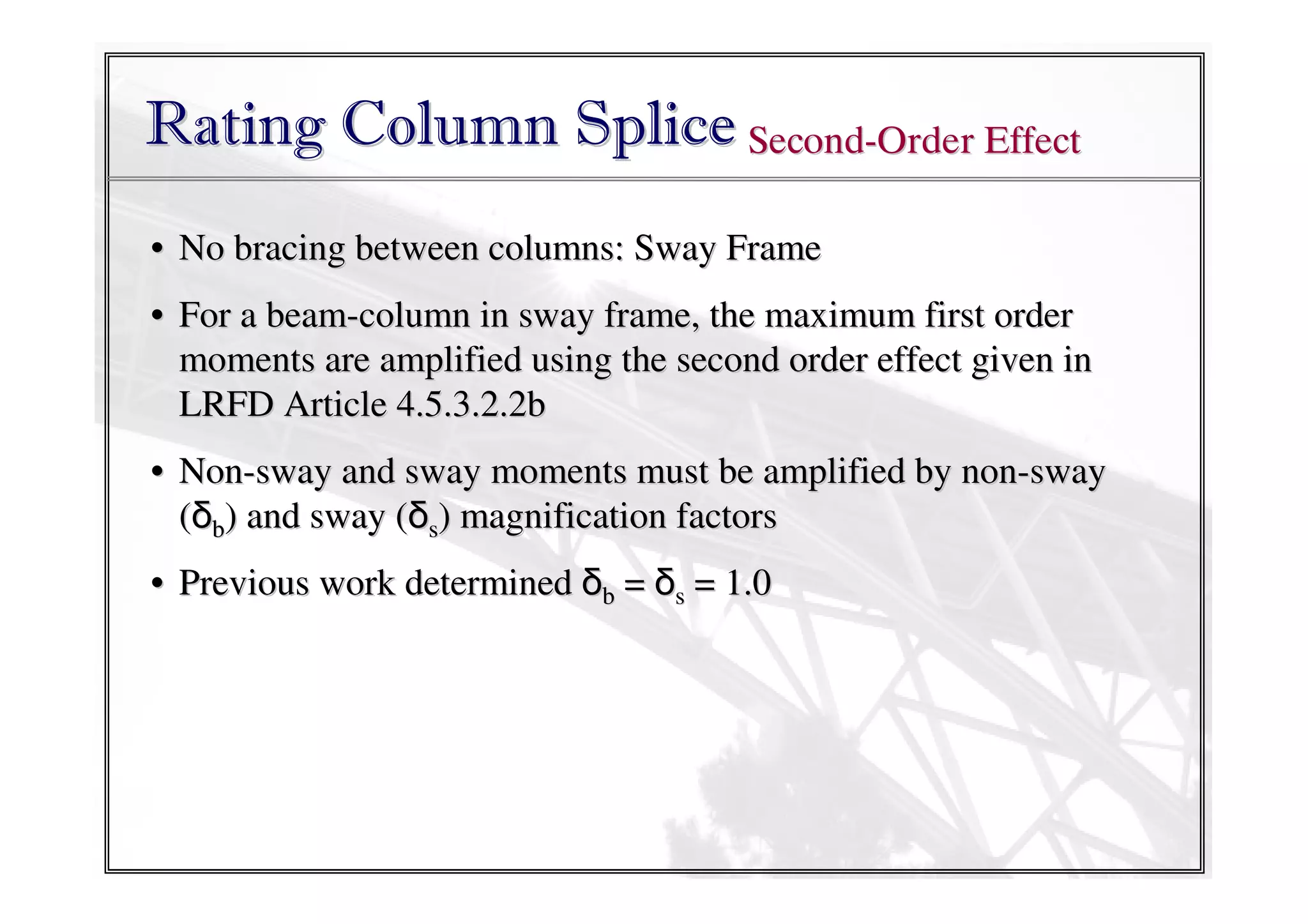
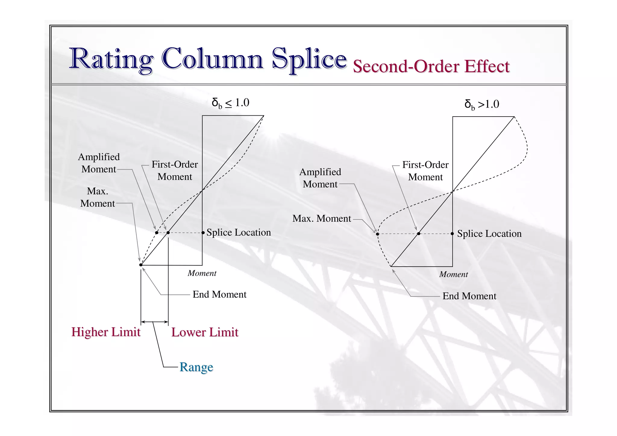
![Rating Column Splice Limit States
Flange Plates:
Gross yielding
PL based
Limit States Net fracture
Block shear
Rivet based Shear strength of rivets
Limit States Bearing strength of PL
Total Capacity = smaller of
[φRnFlangePL + φRnAngles]PL-Based
[φRnFlangePL + φRnAngles]Rivet-Based
Angles:
Gross yielding
Net fracture
Block shear
Shear strength of rivets
Bearing strength of PL](https://image.slidesharecdn.com/sapienzauniversityofrome60minpartiiconnectionsmodified-131208082842-phpapp01/75/CM-Jauregui-Sapienza-University-of-Rome-60-min-part-ii-connections-modified-38-2048.jpg)

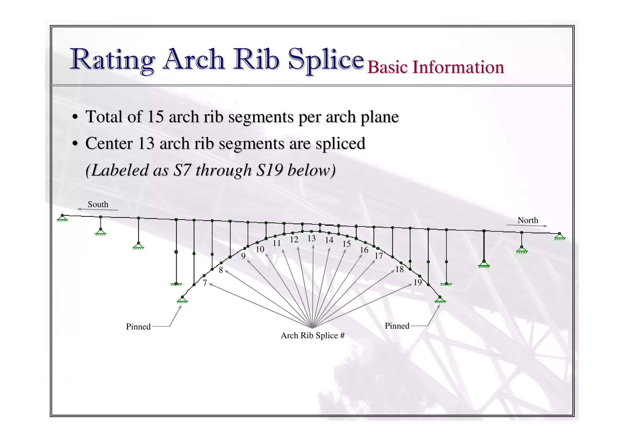


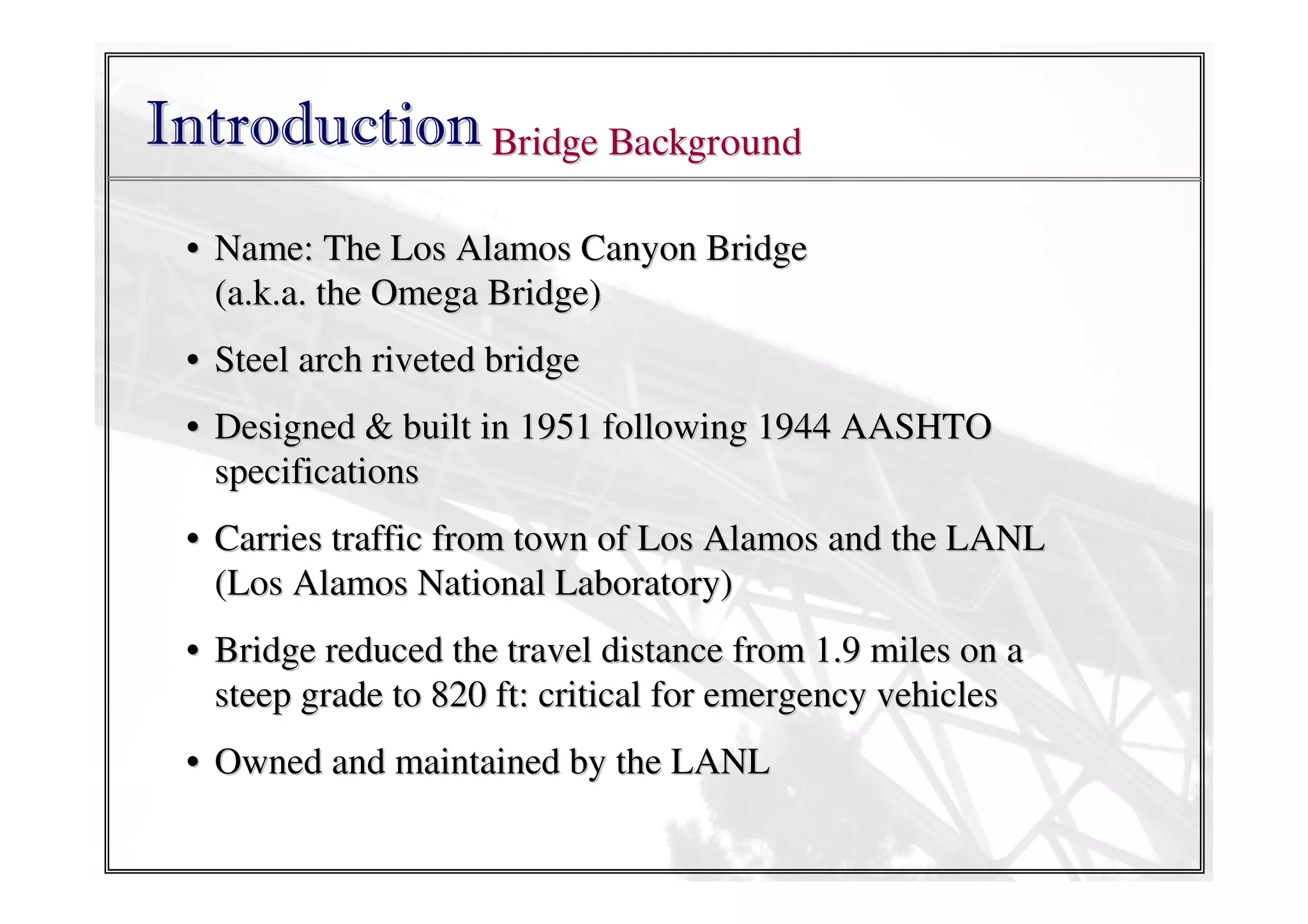
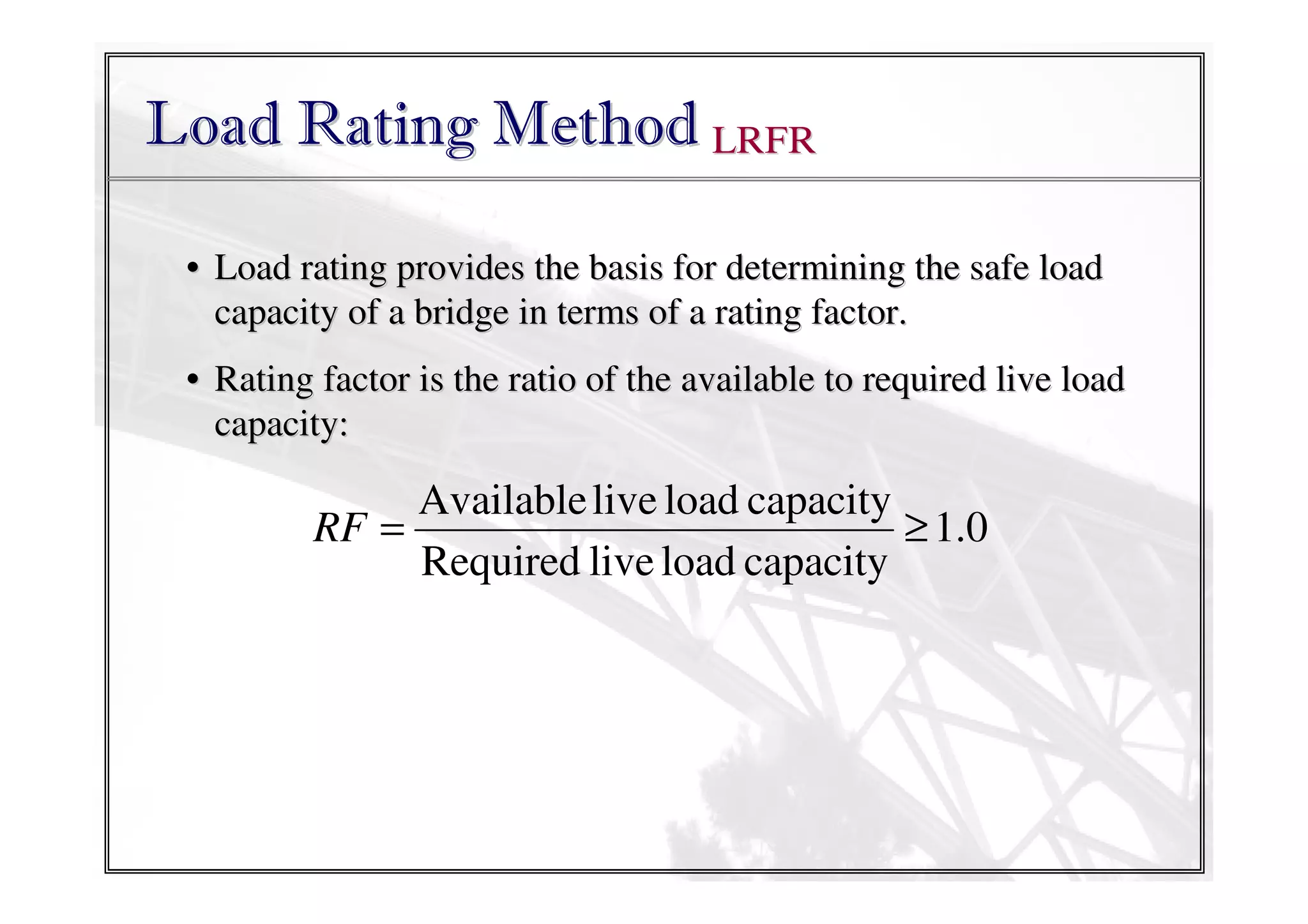
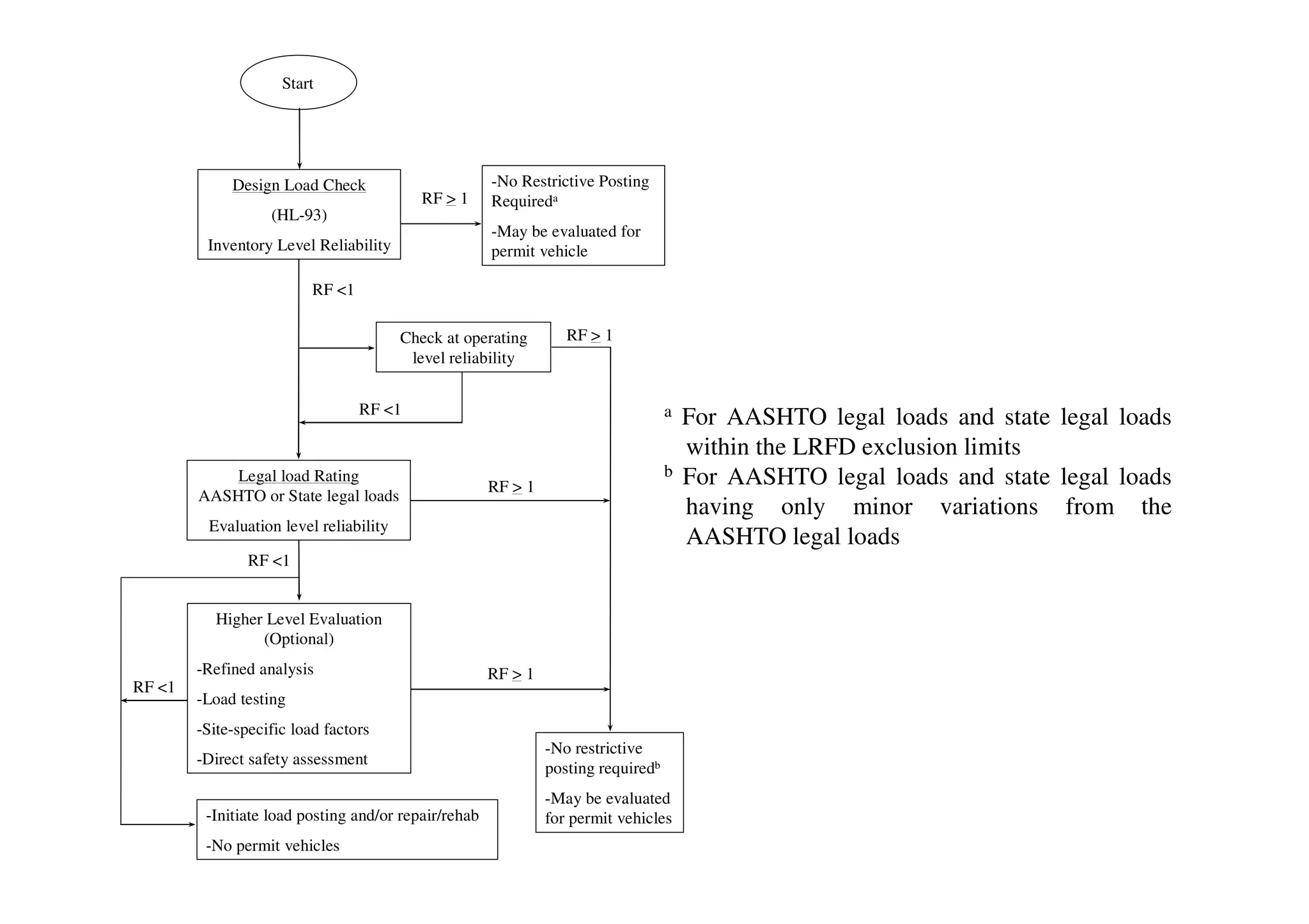
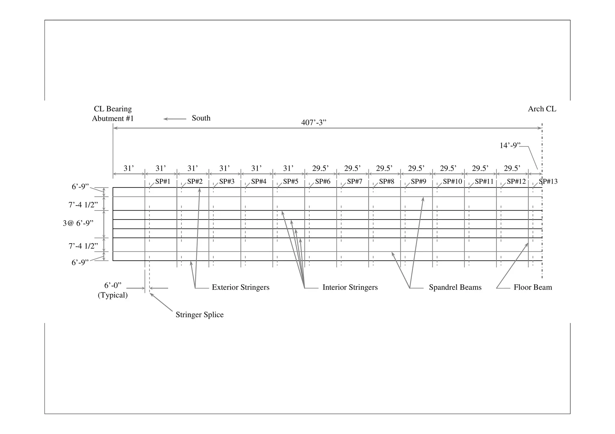
The document details the load rating methodology for the Los Alamos Canyon Bridge, a riveted steel arch bridge built in 1951. It outlines the load rating process using the Load and Resistance Factor Rating (LRFR) method, which assesses the bridge's capacity through various rating factors and design load checks. Additionally, it provides specific load ratings for the bridge's components, including stringers, splices, and columns, while emphasizing the importance of evaluating connection capacities to prevent critical failures.


![Vibe Coding vs. Spec-Driven Development [Free Meetup]](https://cdn.slidesharecdn.com/ss_thumbnails/vibecodingvsspecdrivendevelopment-251209105622-43f455e7-thumbnail.jpg?width=640&height=640&fit=bounds)


