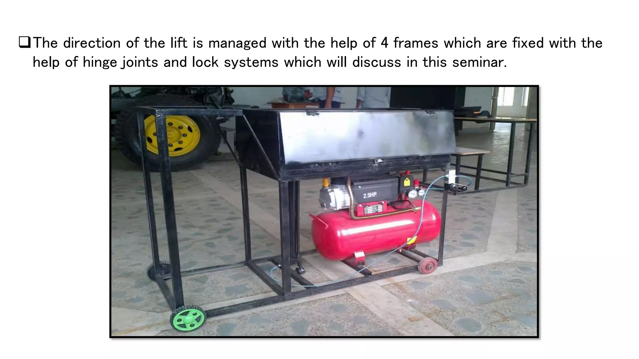
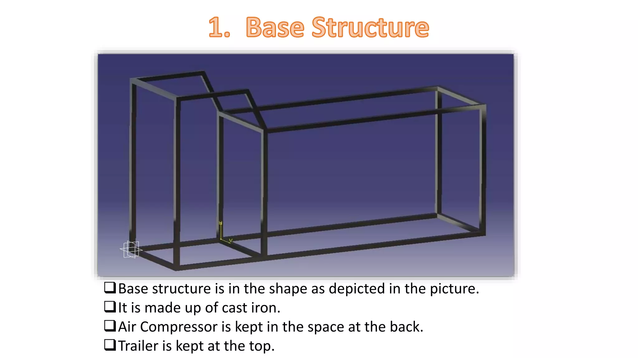
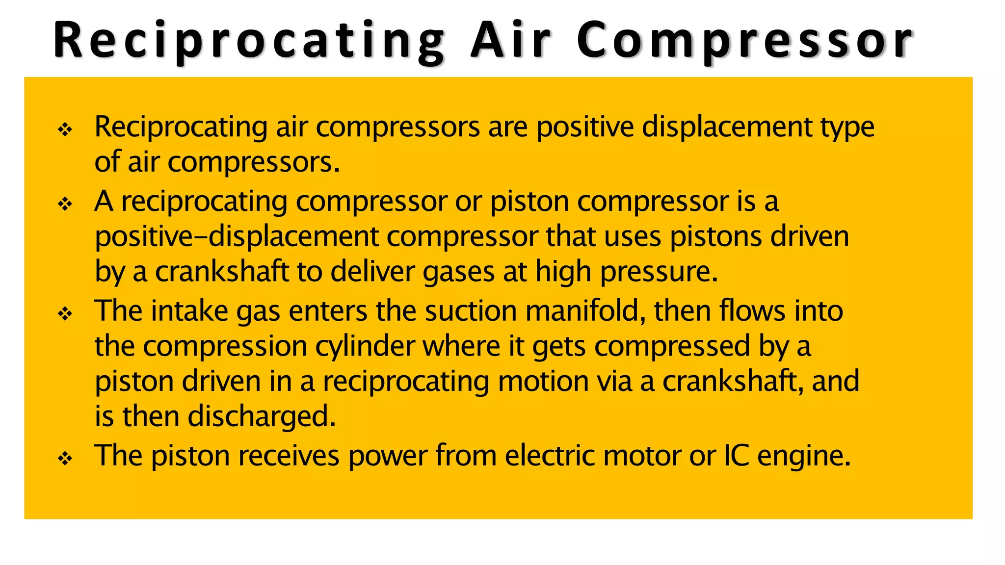
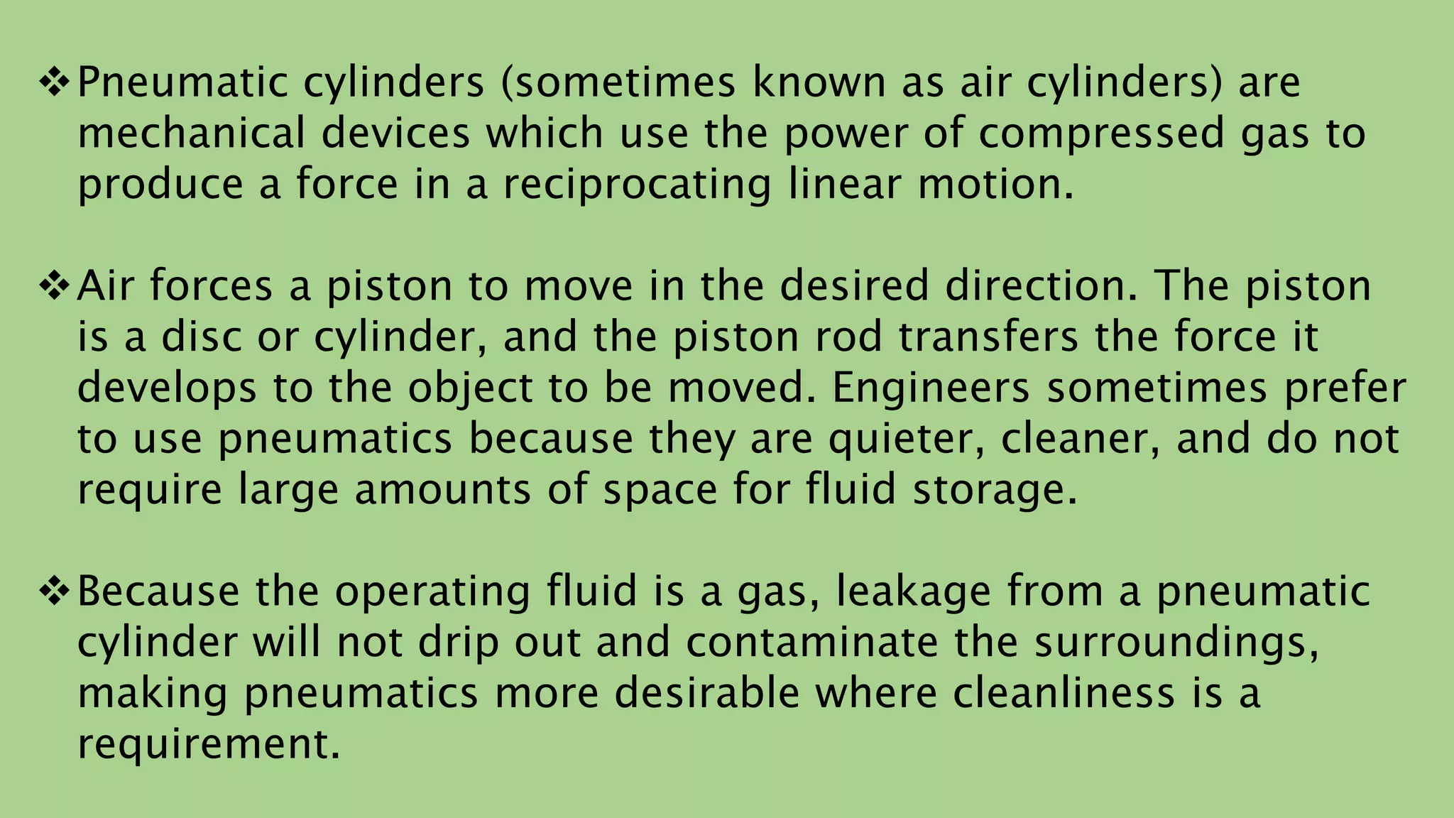
A Project Seminar on
3 AXIS PNEUMATIC TRAILER
Batch : 2011-2015
Regd. No.: 1101229332 – 1101229341
Department of Mechanical Engineering,
Dhaneswar Rath Institute of Engineering and Management Studies, Cuttack
Biju Patnaik University of Technology,
Odisha
 A 3 axis pneumatic trailer is a lifting system in automobile at the time of
emergency. In this lifting system pneumatically operated one, here the additional
pneumatic cylinder and control valve is provided to the automobile itself.
 The advantageous property of this machine is that the trailer at the back can be
lifted diagonally in three direction to unload the goods i.e. Back side, Left side and
Right side.
 A control valve is used to activate/deactivate the air input. The valve is opened at
the time of emergency and the compressed air goes back to the pneumatic
cylinder. Then the compressed air passes through the tube , and then pushes the
pneumatic cylinder, so that the lifting is applied at the time of opened cylinder.
The direction of the lift is managed with the help of 4 frames which are fixed with the
help of hinge joints and lock systems which will discuss in this seminar.
1) Base Structure
2) Air Compressor
3) Control Valve
4) Pneumatic Cylinder
5) Trailer
Base structure is in the shape as depicted in the picture.
It is made up of cast iron.
Air Compressor is kept in the space at the back.
Trailer is kept at the top.
 An air compressor is a device that converts power (usually from an
electric motor, a diesel engine or a gasoline engine) into potential energy
by forcing air into a smaller volume and thus increasing its pressure.
 The energy in the compressed air can be stored
while the air remains pressurized. The energy can
be used for a variety of applications, usually by
utilizing the kinetic energy of the air as it is
depressurized.
Air compressors are classified according to method of energy transfer and
pressure generation.
i.e. Positive Displacement Compressors and Dynamic Compressors
Positive displacement compressors work on the principle of increasing the
pressure of air by reducing the volume of air in an enclosed chamber.
Dynamic compressors works on the principle of imparting the energy by
rotating vanes of impeller on air flowing through casing that increases
pressure in air.
AirCompressor
Positive
Displacement
Reciprocating
Rotatry
Dynamic
Centrifugal
Axial Flow
Ejector
Reciprocating Air Compressor
 Reciprocating air compressors are positive displacement type
of air compressors.
 A reciprocating compressor or piston compressor is a
positive-displacement compressor that uses pistons driven
by a crankshaft to deliver gases at high pressure.
 The intake gas enters the suction manifold, then flows into
the compression cylinder where it gets compressed by a
piston driven in a reciprocating motion via a crankshaft, and
is then discharged.
 The piston receives power from electric motor or IC engine.
Intake Air Cleaner
Cylinder
Pressure Gauge
Pressure Control
Valve
Air Outlet
Compressed Air
Tank
Safety Guard
Electric Motor
Safety Valve
Belt
Single Stage Reciprocating Air Compressor
Flow Control
Valve
Ball Valve
Direction
Control Valve
Flow Control Valve
Flow Control Valves are used to reduce the
rate of flow in a section of a pneumatic circuit,
resulting in a slower actuator speed. Flow
Control Valves control flow in only one
direction, allowing free flow in the opposite
direction.
Ball Valve
A ball valve is a form of quarter-turn valve which uses a hollow,
perforated and pivoting ball (called a "floating ball") to control flow
through it. It is open when the ball's hole is in line with the flow and
closed when it is pivoted 90-degrees by the valve handle. The handle
lies flat in alignment with the flow when open, and is perpendicular to
it when closed, making for easy visual confirmation of the valve's
status.
Direction Control Valve
The direction control valve is used to control the direction of flow of
compressed air. Usually classified into normally open(NO) and
normally closed (NC)valves. The normally open valves will permit flow
from inlet port of valve to outlet port normally the flow will be cut by
changing the position of the valve. The normally closed valves will not
permit flow from inlet port of valve to outlet port normally the flow
will be permitted only by changing the position of the valve.
Pneumatic cylinders (sometimes known as air cylinders) are
mechanical devices which use the power of compressed gas to
produce a force in a reciprocating linear motion.
Air forces a piston to move in the desired direction. The piston
is a disc or cylinder, and the piston rod transfers the force it
develops to the object to be moved. Engineers sometimes prefer
to use pneumatics because they are quieter, cleaner, and do not
require large amounts of space for fluid storage.
Because the operating fluid is a gas, leakage from a pneumatic
cylinder will not drip out and contaminate the surroundings,
making pneumatics more desirable where cleanliness is a
requirement.
Ball joints are spherical bearings that connect the control arms to the steering
knuckles. A ball joint is used for allowing free movement in two planes at the
same time, including rotating in those planes. Combining two such joints with
control arms enables motion in all three planes, allowing the front end of an
automobile to be steered and a spring and shock (damper) suspension to make
the ride comfortable.
Ball Joints
x- axis
y- axis
(-y) -axis
along x-axis along y-axis
Frame 1
Frame 2
Frame 3
Fixed Frame
When we need to lift the trailer at the backward direction then all the frames
i.e. F1 + F2 + F3 are locked together to act as a single frame and the hinge at the dotted
line works to undergo the operation.
When we need to lift the trailer in left-direction then frames F2 + F3 are locked
together with the fixed frame to act as one and on the other hand F1 act as another
frame. Hinge at the place of dotted line works to undergo the operation.
When we need to lift the trailer right-ward then frames F1 + F2 are locked together to
act as one and on the other hand F3 is locked with the fixed frame to act as another
frame. Hinge at the place of dotted line works to undergo the operation.
3 AXIS PNEUMATIC TRAILER

3 AXIS PNEUMATIC TRAILER

  • 1.
    A Project Seminaron 3 AXIS PNEUMATIC TRAILER Batch : 2011-2015 Regd. No.: 1101229332 – 1101229341 Department of Mechanical Engineering, Dhaneswar Rath Institute of Engineering and Management Studies, Cuttack Biju Patnaik University of Technology, Odisha
  • 2.
     A 3axis pneumatic trailer is a lifting system in automobile at the time of emergency. In this lifting system pneumatically operated one, here the additional pneumatic cylinder and control valve is provided to the automobile itself.  The advantageous property of this machine is that the trailer at the back can be lifted diagonally in three direction to unload the goods i.e. Back side, Left side and Right side.  A control valve is used to activate/deactivate the air input. The valve is opened at the time of emergency and the compressed air goes back to the pneumatic cylinder. Then the compressed air passes through the tube , and then pushes the pneumatic cylinder, so that the lifting is applied at the time of opened cylinder.
  • 3.
    The direction ofthe lift is managed with the help of 4 frames which are fixed with the help of hinge joints and lock systems which will discuss in this seminar.
  • 4.
    1) Base Structure 2)Air Compressor 3) Control Valve 4) Pneumatic Cylinder 5) Trailer
  • 5.
    Base structure isin the shape as depicted in the picture. It is made up of cast iron. Air Compressor is kept in the space at the back. Trailer is kept at the top.
  • 6.
     An aircompressor is a device that converts power (usually from an electric motor, a diesel engine or a gasoline engine) into potential energy by forcing air into a smaller volume and thus increasing its pressure.  The energy in the compressed air can be stored while the air remains pressurized. The energy can be used for a variety of applications, usually by utilizing the kinetic energy of the air as it is depressurized.
  • 7.
    Air compressors areclassified according to method of energy transfer and pressure generation. i.e. Positive Displacement Compressors and Dynamic Compressors Positive displacement compressors work on the principle of increasing the pressure of air by reducing the volume of air in an enclosed chamber. Dynamic compressors works on the principle of imparting the energy by rotating vanes of impeller on air flowing through casing that increases pressure in air.
  • 8.
  • 9.
    Reciprocating Air Compressor Reciprocating air compressors are positive displacement type of air compressors.  A reciprocating compressor or piston compressor is a positive-displacement compressor that uses pistons driven by a crankshaft to deliver gases at high pressure.  The intake gas enters the suction manifold, then flows into the compression cylinder where it gets compressed by a piston driven in a reciprocating motion via a crankshaft, and is then discharged.  The piston receives power from electric motor or IC engine.
  • 10.
    Intake Air Cleaner Cylinder PressureGauge Pressure Control Valve Air Outlet Compressed Air Tank Safety Guard Electric Motor Safety Valve Belt Single Stage Reciprocating Air Compressor
  • 12.
    Flow Control Valve Ball Valve Direction ControlValve Flow Control Valve Flow Control Valves are used to reduce the rate of flow in a section of a pneumatic circuit, resulting in a slower actuator speed. Flow Control Valves control flow in only one direction, allowing free flow in the opposite direction.
  • 13.
    Ball Valve A ballvalve is a form of quarter-turn valve which uses a hollow, perforated and pivoting ball (called a "floating ball") to control flow through it. It is open when the ball's hole is in line with the flow and closed when it is pivoted 90-degrees by the valve handle. The handle lies flat in alignment with the flow when open, and is perpendicular to it when closed, making for easy visual confirmation of the valve's status. Direction Control Valve The direction control valve is used to control the direction of flow of compressed air. Usually classified into normally open(NO) and normally closed (NC)valves. The normally open valves will permit flow from inlet port of valve to outlet port normally the flow will be cut by changing the position of the valve. The normally closed valves will not permit flow from inlet port of valve to outlet port normally the flow will be permitted only by changing the position of the valve.
  • 15.
    Pneumatic cylinders (sometimesknown as air cylinders) are mechanical devices which use the power of compressed gas to produce a force in a reciprocating linear motion. Air forces a piston to move in the desired direction. The piston is a disc or cylinder, and the piston rod transfers the force it develops to the object to be moved. Engineers sometimes prefer to use pneumatics because they are quieter, cleaner, and do not require large amounts of space for fluid storage. Because the operating fluid is a gas, leakage from a pneumatic cylinder will not drip out and contaminate the surroundings, making pneumatics more desirable where cleanliness is a requirement.
  • 18.
    Ball joints arespherical bearings that connect the control arms to the steering knuckles. A ball joint is used for allowing free movement in two planes at the same time, including rotating in those planes. Combining two such joints with control arms enables motion in all three planes, allowing the front end of an automobile to be steered and a spring and shock (damper) suspension to make the ride comfortable. Ball Joints x- axis y- axis (-y) -axis
  • 19.
  • 21.
    Frame 1 Frame 2 Frame3 Fixed Frame
  • 22.
    When we needto lift the trailer at the backward direction then all the frames i.e. F1 + F2 + F3 are locked together to act as a single frame and the hinge at the dotted line works to undergo the operation.
  • 23.
    When we needto lift the trailer in left-direction then frames F2 + F3 are locked together with the fixed frame to act as one and on the other hand F1 act as another frame. Hinge at the place of dotted line works to undergo the operation.
  • 24.
    When we needto lift the trailer right-ward then frames F1 + F2 are locked together to act as one and on the other hand F3 is locked with the fixed frame to act as another frame. Hinge at the place of dotted line works to undergo the operation.