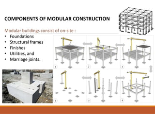
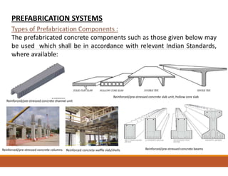
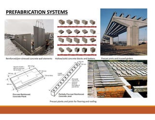
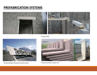
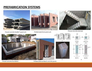
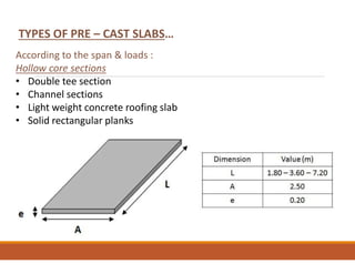
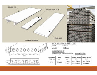
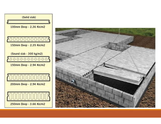
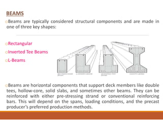
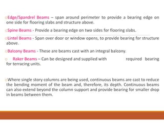
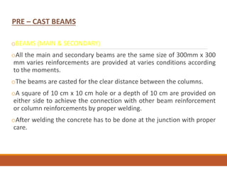
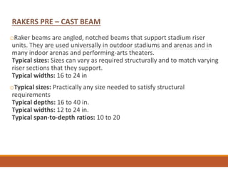
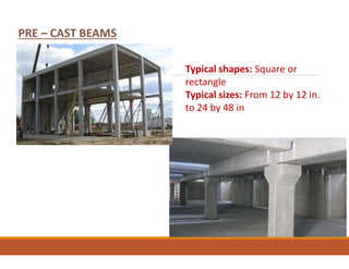
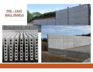
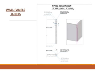
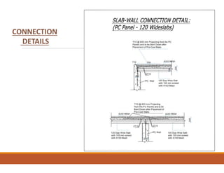
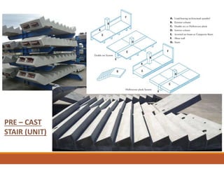
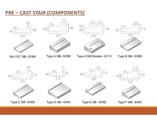
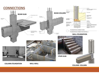
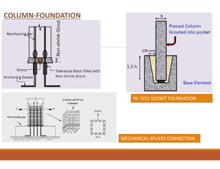
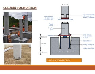
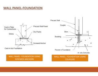
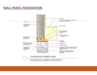
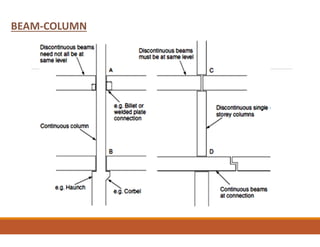
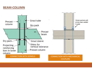
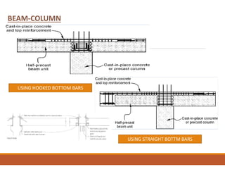
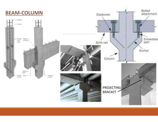
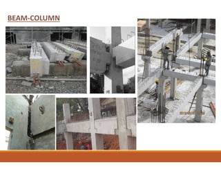
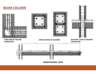
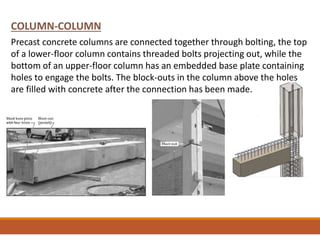
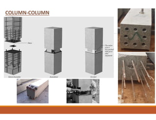
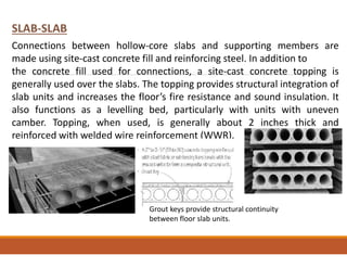
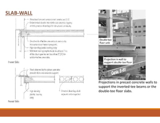
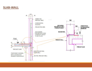
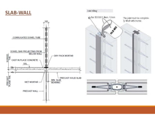
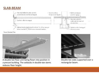
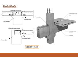
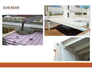
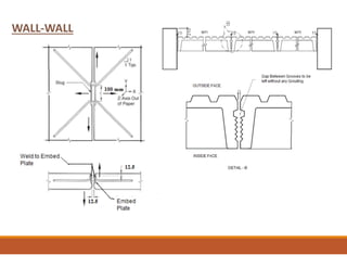
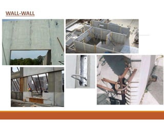
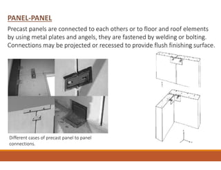
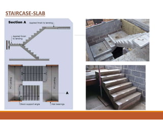
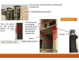
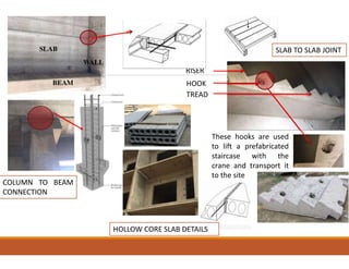
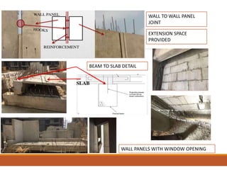
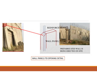
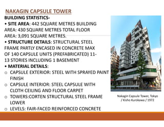
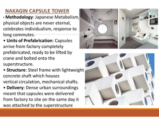
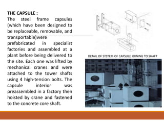
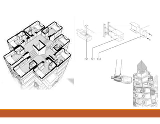
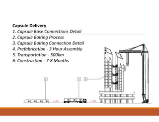
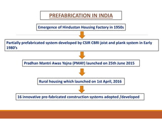
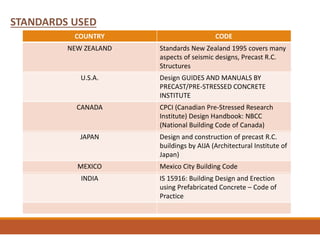
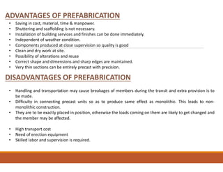
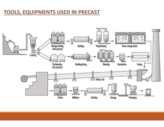
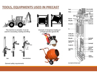
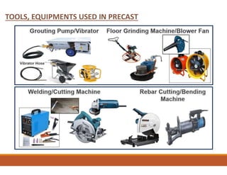
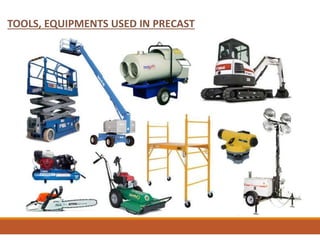
ADVANCED STRUCTURAL
CONCRETES MATERIALS FOR PRESTRESSING
(Building Construction, RAR-902)
(DATE : 28 JAN 2021)
GUIDED BY
AR. SHAINA KOCHAR
PRESENTED BY
CHANDAN BAGHEL
PRASHANT SINGH
B. ARCH – 5TH YEAR (9TH SEM)
MODULAR COMPONENTS …….
COMPONENTS OF MODULAR CONSTRUCTION
Modular buildings consist of on-site :
• Foundations
• Structural frames
• Finishes
• Utilities, and
• Marriage joints.
PREFABRICATION SYSTEMS
•The system of prefabricated construction depends on the - extent of
the use of prefabricated components,
• - Their materials,
• - Sizes and the technique adopted for their manufacture
• - Use in building
Types of Prefabrication Components :
The prefabricated concrete components such as those given below may
be used which shall be in accordance with relevant Indian Standards,
where available:
PREFABRICATION SYSTEMS
Reinforced/pre-stressed concrete channel unit
Reinforced/pre-stressed concrete slab unit, hollow core slab
Reinforced/pre-stressed concrete beams
Reinforced concrete waffle slab/shells
Reinforced/pre-stressed concrete columns
PREFABRICATION SYSTEMS
Reinforced/pre-stressed concrete wall elements Hollow/solid concrete blocks and battens Precast joists and trussed girders
Precast planks and joists for flooring and roofing
PREFABRICATION SYSTEMS
Precast lintel
Reinforced/pre-stressed concrete trusses Precast concrete L-panel unit
PREFABRICATION SYSTEMS
Prefabricated brick panel unit
Prefabricated sandwich concrete panels
Precast concrete double T-panel unit
Precast concrete staircase
Precast concrete foundation
NOTE — The elements may be cast at the site or off the site.
Open Prefabrication system,
• There are two categories of open prefab system; depending on the
extent of prefabrication used in the construction Partial
prefabrication system.
• This system basically uses precast roofing and flooring components
and other minor elements like lintels, CHAJJAS, kitchen sills in
conventional building construction.
• The structural system could be in the form of in-situ framework or
load bearing walls.
Full prefabrication system
In this system almost all the structural components are
prefabricated. The filler walls may be of brick/block masonry or of
any other locally available materials.
Large Panel Prefabrication System
This system is based on the use of large prefab components. The
components used are precast concrete large panels for walls,
floors, roofs, balconies, staircases, etc. The casting of the
components could be at the site or off the site.
Depending upon the extent of prefabrication, this system can also lend itself
to partial prefab system and full prefab system.
Structural scheme with precast large panel walls can be classified Precast
walls:
Based on the structural functions of the walls, the precast walls may be
classified as:
a) Load bearing walls;
b) Non-load bearing walls; and
c) Shear walls.
Based on construction, the precast walls may be classified as:
a) Homogeneous walls — which could be solid, hollow or ribbed;
b) b) Non-homogeneous walls— these could be composite or sandwich
panels.
Based on their locations and functional
requirements the precast walls may also be classified as:
a) External walls, which may be load bearing or non-load bearing depending
upon the lay-out; these are usually non-homogeneous walls of sandwiched
type to impart better thermal comforts; and
COMPONENTS
The dimensions of precast elements shall meet the design requirements.
However, the actual dimensions shall be the preferred dimensions as follows:
a) Flooring and Roofing Scheme
— Precast slabs or other precast structural flooring units:
1) Length — Nominal length shall be in multiples of 1M
2) Width — Nominal width shall be in multiples of 0.5 M
3) Overall thickness — Overall thickness shall be in multiples
of 0.1 M
B) Nominal length shall be in multiples of 1 M
1) width — nominal width shall be in multiples of 0.1 m
2) overall depth — overall depth of the floor zone shall be in multiples of
0.1 m
C) columns
1) height — height of columns for industrial shall be 1 M and other
building 1M
2) lateral dimensions — overall lateral dimension or diameter of columns
shall be in multiples of 0.1 m
D) walls thickness
— the nominal thickness of walls shall be in multiples of 0.1m
E) staircase width — nominal width shall be in multiples of 1 M
f) Lintels
1) Length — Nominal length shall be in multiples of 1 M
2) Width — Nominal width shall be in multiples of 0.1M
3) Depth — Nominal depth shall be in multiples of 0.1 M
g) Sunshades/Chajja Projections
1) Length — Nominal length shall be in multiples of 1
Projection
— Nominal length shall be in multiples of 0.5 M
PRE – CAST SLABS…..
• The roofing slab/flooring slab system consists of planks, which is
supported over R.C.C Joist.
• The planks can be made in any one of the following form with or
without pre-stressing.
• The usual widths of these types of slabs are 0.5 m & spanning to
the requirement up to a maximum limit of 5 m without pre-
stressing.
• The thicknesses of planks are casted in two steps with different
mold to access monolithic action with adjacent slab by putting
necessary reinforcement & concreting site.
SLABS
TYPES OF PRE – CAST SLABS…
According to the span & loads :
Hollow core sections
• Double tee section
• Channel sections
• Light weight concrete roofing slab
• Solid rectangular planks
PRE – CAST BEAMS…..
oBeams are typically considered structural components and are made in
one of three key shapes:
oRectangular
oInverted Tee Beams
oL-Beams
oBeams are horizontal components that support deck members like double
tees, hollow-core, solid slabs, and sometimes other beams. They can be
reinforced with either pre-stressing strand or conventional reinforcing
bars. This will depend on the spans, loading conditions, and the precast
producer’s preferred production methods.
BEAMS
oEdge/Spandrel Beams – span around perimeter to provide a bearing edge on
one side for flooring slabs and structure above.
oSpine Beams - Provide a bearing edge on two sides for flooring slabs.
oLintel Beams - Span over door or window opens, to provide bearing for structure
above.
oBalcony Beams - These are beams cast with an integral balcony.
o Raker Beams – Can be designed and supplied with required bearing
for terracing units.
oWhere single story columns are being used, continuous beams are cast to reduce
the bending moment of the beam and, therefore, its depth. Continuous beams
can also extend beyond the column support and provide bearing for smaller drop
in beams between them.
PRE – CAST BEAMS
oBEAMS (MAIN & SECONDARY)
oAll the main and secondary beams are the same size of 300mm x 300
mm varies reinforcements are provided at varies conditions according
to the moments.
oThe beams are casted for the clear distance between the columns.
oA square of 10 cm x 10 cm hole or a depth of 10 cm are provided on
either side to achieve the connection with other beam reinforcement
or column reinforcements by proper welding.
oAfter welding the concrete has to be done at the junction with proper
care.
oRaker beams are angled, notched beams that support stadium riser
units. They are used universally in outdoor stadiums and arenas and in
many indoor arenas and performing-arts theaters.
Typical sizes: Sizes can vary as required structurally and to match varying
riser sections that they support.
Typical widths: 16 to 24 in
oTypical sizes: Practically any size needed to satisfy structural
requirements
Typical depths: 16 to 40 in.
Typical widths: 12 to 24 in.
Typical span-to-depth ratios: 10 to 20
RAKERS PRE – CAST BEAM
PRE – CAST BEAMS
Typical shapes: Square or
rectangle
Typical sizes: From 12 by 12 in.
to 24 by 48 in
PRE – CAST BEAMS
PRE – CAST WALL PANELS…..
oThe wall panels are casted with all fixing like door, ventilation, window
frames. These wall panels are non load bearing wall. Therefore neglect
solid rectangular cross section wall panel with R.C.C. From the view of
thermal effects and safety . the minimum of 150 mm is provided as wall
thickness.
oThis wall is a sandwich type.
oThat is cellular concrete blocks of 75 mm thick is sandwiched by R.C.C.
M25 grade concrete to a thickness of 37.5 mm on either face with
minimum reinforcement
oSince, the walls are in steel moulds there will be no need for plastering
on either face of wall.
oThis is one of advantage of precast wall panels.
PRE – CAST WALL PANELS
PRE – CAST
WALL PANELS
WALL PANELS
JOINTS
CONNECTION
DETAILS
PRE – CAST STAIRS…..
PRE – CAST STAIR (INSTALATION)
PRE – CAST
STAIR (UNIT)
R.C.C. FILLING
STAIR FORMWORK
STAIR OUT SIDE
UNIT ENTRY DOOR
WALL
SHARE WALL
PRE – CAST STAIR (COMPONENTS)
PRE – CAST COLUMN…..
• Precast Columns are most suited for industrial, commercial and IT bay
buildings where columns have thicker sections.
• Columns can either be pre-casted on site if space permits, or they can
be manufactured in our factory and transported to the site.
PRE – CAST COLUMNS
CONNECTIONS
BEAM-SLAB
BEAM-COLUMN
WALL-FOUNDATION
COLUMN-FOUNDATION
COLUMN -COLUMN
WALL-WALL
STAIR-SLAB
COLUMN-FOUNDATION
The method of connection to the foundation and to the column above will vary with manufacturer.
Foundation connection may be via a base plate connected to the column or by reinforcing bars
projecting from the end of the column passing into sleeves that are subsequently filled with grout.
Alternatively, a column may be set into a preformed hole in a foundation block and grouted into
position. Column to base connections may be by threaded rods joined with an appropriate
connector; with concrete subsequently cast round to the dimensions of the cross-section of the
column.
COLUMN-FOUNDATION
MECHANICAL SPLICES CONNECTION
IN- SITU SOCKET FOUNDATION
COLUMN-FOUNDATION
BASE PLATE CONNECTION
WALL PANEL-FOUNDATION
WALL PANEL- FOUNDATION USING
SCREWED ANCHORS
WALL PANEL- FOUNDATION USING
COUPLERS
WALL PANEL-FOUNDATION
BEAM-COLUMN
BEAM-COLUMN
CONNECTION WITH DOWELS CONNECTION WITH MECHANICAL
COUPLERS
BEAM-COLUMN
USING HOOKED BOTTOM BARS
USING STRAIGHT BOTTM BARS
BEAM-COLUMN
PROJECTING
BRACKET
BEAM-COLUMN
BEAM-COLUMN
PLAN VIEW OF THE END
CONNECTION
CROSS SECTION OF COLUMNS SECTIONAL VIEW OF INTERIOR
CONNECTION
LONGITUDINAL VIEW
COLUMN-COLUMN
Precast concrete columns are connected together through bolting, the top
of a lower-floor column contains threaded bolts projecting out, while the
bottom of an upper-floor column has an embedded base plate containing
holes to engage the bolts. The block-outs in the column above the holes
are filled with concrete after the connection has been made.
COLUMN-COLUMN
SLAB-SLAB
Connections between hollow-core slabs and supporting members are
made using site-cast concrete fill and reinforcing steel. In addition to
the concrete fill used for connections, a site-cast concrete topping is
generally used over the slabs. The topping provides structural integration of
slab units and increases the floor’s fire resistance and sound insulation. It
also functions as a levelling bed, particularly with units with uneven
camber. Topping, when used, is generally about 2 inches thick and
reinforced with welded wire reinforcement (WWR).
Grout keys provide structural continuity
between floor slab units.
SLAB-WALL
Projections in precast concrete walls to
support the inverted-tee beams or the
double-tee floor slabs.
SLAB-WALL
SLAB-WALL
SLAB-BEAM
A double-tee floor unit being flown into position in
a precast building. The setbacks in double-tee stems
reduces floor height.
Double tee slabs supported over a
rectangular beam.
SLAB-BEAM
USES OF REBARS
SLAB-BEAM
WALL-WALL
WALL-WALL
PANEL-PANEL
Precast panels are connected to each others or to floor and roof elements
by using metal plates and angels, they are fastened by welding or bolting.
Connections may be projected or recessed to provide flush finishing surface.
Different cases of precast panel to panel
connections.
STAIRCASE-SLAB
The Structure. Are made from prefabricated
components.
Prefabricated wall panels
This is the detail
of two vertical
joinery of wall
panel
The wall panels
are designed
according to the
opening in the
wall like door,
windows Etc.
Beam
Prefabricated column
Stirrups
WALL TO WALL JOINT
COLUMN DETAIL
RISER
These hooks are used
to lift a prefabricated
staircase with the
crane and transport it
to the site
HOOK
TREAD
COLUMN TO BEAM
CONNECTION
HOLLOW CORE SLAB DETAILS
SLAB TO SLAB JOINT
WALL TO WALL PANEL
JOINT
WALL PANELS WITH WINDOW OPENING
BEAM TO SLAB DETAIL
EXTENSION SPACE
PROVIDED
WALL PANELS TO OPENING DETAIL
Nakagin Capsule Tower, Tokyo / Kisho
Kurokawa / 1972
Habitat 67, Montreal / Moshe Safdie / 1967
Dymaxion House / Richard Buckminster Fuller / 1945
Torten Estate, Dessau / Walter Gropius
and Hannes Meyer / 1926-28
Furniture House 1, Yamanashi / Shigeru
Ban / 1995
McDonalds, UK
Nakagin Capsule Tower, Tokyo
/ Kisho Kurokawa / 1972
NAKAGIN CAPSULE TOWER
BUILDING STATISTICS-
• SITE AREA: 442 SQUARE METRES BUILDING
AREA: 430 SQUARE METRES TOTAL FLOOR
AREA: 3,091 SQUARE METRES.
• STRUCTURE DETAILS: STRUCTURAL STEEL
FRAME PARTLY ENCASED IN CONCRETE MAX
OF 140 CAPSULE UNITS (PREFABRICATED) 11-
13 STORIES INCLUDING 1 BASEMENT
• MATERIAL DETAILS:
o CAPSULE EXTERIOR: STEEL WITH SPRAYED PAINT
FINISH
o CAPSULE INTERIOR: STEEL CAPSULE WITH
CLOTH CEILING AND FLOOR CARPET
o TOWERS:CORTEN STRUCTURAL STEEL FRAME
LOWER
o LEVELS: FAIR-FACED REINFORCED CONCRETE
NAKAGIN CAPSULE TOWER
• Methodology: Japanese Metabolism,
physical objects are never eternal,
celebrates individualism, response to
long commutes.
• Units of Prefabrication: Capsules
arrive from factory completely
prefabricated, ready to be lifted by
crane and bolted onto the
superstructure.
• Structure: Steel frame with lightweight
concrete shaft which houses
vertical circulation, mechanical shafts.
• Delivery: Dense urban surroundings
meant that capsules were delivered
from factory to site on the same day it
was attached to the superstructure
THE CAPSULE :
The steel frame capsules
(which have been designed to
be replaceable, removable, and
transportable)were
prefabricated in specialist
factories and assembled at a
plant before being delivered to
the site. Each one was lifted by
mechanical cranes and were
attached to the tower shafts
using 4 high-tension bolts. The
capsule interior was
preassembled in a factory then
hoisted by crane and fastened
to the concrete core shaft.
DETAIL OF SYSTEM OF CAPSULE JOINING TO SHAFT
Capsule Delivery
1. Capsule Base Connections Detail
2. Capsule Bolting Process
3. Capsule Bolting Connection Detail
4. Prefabrication - 3 Hour Assembly
5. Transportation - 500km
6. Construction - 7-8 Months
PREFABRICATION IN INDIA
Emergence of Hindustan Housing Factory in 1950s
Partially prefabricated system developed by CSIR CBRI joist and plank system in Early
1980’s
Pradhan Mantri Awas Yojna (PMAY) launched on 25th June 2015
Rural housing which launched on 1st April, 2016
16 innovative pre-fabricated construction systems adopted /developed
STANDARDS USED
COUNTRY CODE
NEW ZEALAND Standards New Zealand 1995 covers many
aspects of seismic designs, Precast R.C.
Structures
U.S.A. Design GUIDES AND MANUALS BY
PRECAST/PRE-STRESSED CONCRETE
INSTITUTE
CANADA CPCI (Canadian Pre-Stressed Research
Institute) Design Handbook: NBCC
(National Building Code of Canada)
JAPAN Design and construction of precast R.C.
buildings by AIJA (Architectural Institute of
Japan)
MEXICO Mexico City Building Code
INDIA IS 15916: Building Design and Erection
using Prefabricated Concrete – Code of
Practice
EXAMPLES(INDIA)
IOB BUILDING, CHENNAI VIKAS SOUDHA, BANGALORE
ADVANTAGES OF PREFABRICATION
DISADVANTAGES OF PREFABRICATION
• Saving in cost, material, time & manpower.
• Shuttering and scaffolding is not necessary.
• Installation of building services and finishes can be done immediately.
• Independent of weather condition.
• Components produced at close supervision so quality is good
• Clean and dry work at site.
• Possibility of alterations and reuse
• Correct shape and dimensions and sharp edges are maintained.
• Very thin sections can be entirely precast with precision.
• Handling and transportation may cause breakages of members during the transit and extra provision is to
be made.
• Difficulty in connecting precast units so as to produce same effect as monolithic. This leads to non-
monolithic construction.
• They are to be exactly placed in position, otherwise the loads coming on them are likely to get changed and
the member may be affected.
• High transport cost
• Need of erection equipment
• Skilled labor and supervision is required.
TOOLS, EQUIPMENTS USED IN PRECAST
The machine is versatile. It can be
used for excavating, loading and lifting
General safety requirements
Example of dangerous loading of
a freight elevator (goods-lift)
TOOLS, EQUIPMENTS USED IN PRECAST
https://www.deluxemodular.com/learning-center/modular-building-components
https://logixicf.com/technical-library
https://www.pci.org/PCI/Design_Resources/About_Precast/Beams_and_Columns.aspx
http://www.creaghconcrete.co.uk/products/precast-frames/precast-concrete-columns-
beams.html?p=198#
https://theconstructor.org/building/methods-precast-concrete-constructions/26523/
https://theconstructor.org/concrete/lightweight-concrete/1670/
https://www.engineeringenotes.com/concrete-technology/light-weight-concrete/light-weight-
concrete-types-and-applications-concrete-technology/31840
https://www.researchgate.net/publication/324949995_high-strength_concrete_hsc-
material_for_high-rise_buildings
https://cbri.res.in
REFERENCES :

Prefabrication & Pre-CASTING, Advanced Structural Concretes Materials for Pre- Stressing,

  • 1.
    ADVANCED STRUCTURAL CONCRETES MATERIALSFOR PRESTRESSING (Building Construction, RAR-902) (DATE : 28 JAN 2021) GUIDED BY AR. SHAINA KOCHAR PRESENTED BY CHANDAN BAGHEL PRASHANT SINGH B. ARCH – 5TH YEAR (9TH SEM)
  • 2.
  • 3.
    COMPONENTS OF MODULARCONSTRUCTION Modular buildings consist of on-site : • Foundations • Structural frames • Finishes • Utilities, and • Marriage joints.
  • 4.
    PREFABRICATION SYSTEMS •The systemof prefabricated construction depends on the - extent of the use of prefabricated components, • - Their materials, • - Sizes and the technique adopted for their manufacture • - Use in building
  • 5.
    Types of PrefabricationComponents : The prefabricated concrete components such as those given below may be used which shall be in accordance with relevant Indian Standards, where available: PREFABRICATION SYSTEMS Reinforced/pre-stressed concrete channel unit Reinforced/pre-stressed concrete slab unit, hollow core slab Reinforced/pre-stressed concrete beams Reinforced concrete waffle slab/shells Reinforced/pre-stressed concrete columns
  • 6.
    PREFABRICATION SYSTEMS Reinforced/pre-stressed concretewall elements Hollow/solid concrete blocks and battens Precast joists and trussed girders Precast planks and joists for flooring and roofing
  • 7.
    PREFABRICATION SYSTEMS Precast lintel Reinforced/pre-stressedconcrete trusses Precast concrete L-panel unit
  • 8.
    PREFABRICATION SYSTEMS Prefabricated brickpanel unit Prefabricated sandwich concrete panels Precast concrete double T-panel unit Precast concrete staircase Precast concrete foundation
  • 9.
    NOTE — Theelements may be cast at the site or off the site. Open Prefabrication system, • There are two categories of open prefab system; depending on the extent of prefabrication used in the construction Partial prefabrication system. • This system basically uses precast roofing and flooring components and other minor elements like lintels, CHAJJAS, kitchen sills in conventional building construction. • The structural system could be in the form of in-situ framework or load bearing walls.
  • 10.
    Full prefabrication system Inthis system almost all the structural components are prefabricated. The filler walls may be of brick/block masonry or of any other locally available materials. Large Panel Prefabrication System This system is based on the use of large prefab components. The components used are precast concrete large panels for walls, floors, roofs, balconies, staircases, etc. The casting of the components could be at the site or off the site.
  • 11.
    Depending upon theextent of prefabrication, this system can also lend itself to partial prefab system and full prefab system. Structural scheme with precast large panel walls can be classified Precast walls: Based on the structural functions of the walls, the precast walls may be classified as: a) Load bearing walls; b) Non-load bearing walls; and c) Shear walls. Based on construction, the precast walls may be classified as: a) Homogeneous walls — which could be solid, hollow or ribbed; b) b) Non-homogeneous walls— these could be composite or sandwich panels.
  • 12.
    Based on theirlocations and functional requirements the precast walls may also be classified as: a) External walls, which may be load bearing or non-load bearing depending upon the lay-out; these are usually non-homogeneous walls of sandwiched type to impart better thermal comforts; and COMPONENTS The dimensions of precast elements shall meet the design requirements. However, the actual dimensions shall be the preferred dimensions as follows: a) Flooring and Roofing Scheme — Precast slabs or other precast structural flooring units: 1) Length — Nominal length shall be in multiples of 1M 2) Width — Nominal width shall be in multiples of 0.5 M 3) Overall thickness — Overall thickness shall be in multiples of 0.1 M
  • 13.
    B) Nominal lengthshall be in multiples of 1 M 1) width — nominal width shall be in multiples of 0.1 m 2) overall depth — overall depth of the floor zone shall be in multiples of 0.1 m C) columns 1) height — height of columns for industrial shall be 1 M and other building 1M 2) lateral dimensions — overall lateral dimension or diameter of columns shall be in multiples of 0.1 m D) walls thickness — the nominal thickness of walls shall be in multiples of 0.1m E) staircase width — nominal width shall be in multiples of 1 M
  • 14.
    f) Lintels 1) Length— Nominal length shall be in multiples of 1 M 2) Width — Nominal width shall be in multiples of 0.1M 3) Depth — Nominal depth shall be in multiples of 0.1 M g) Sunshades/Chajja Projections 1) Length — Nominal length shall be in multiples of 1 Projection — Nominal length shall be in multiples of 0.5 M
  • 15.
    PRE – CASTSLABS…..
  • 16.
    • The roofingslab/flooring slab system consists of planks, which is supported over R.C.C Joist. • The planks can be made in any one of the following form with or without pre-stressing. • The usual widths of these types of slabs are 0.5 m & spanning to the requirement up to a maximum limit of 5 m without pre- stressing. • The thicknesses of planks are casted in two steps with different mold to access monolithic action with adjacent slab by putting necessary reinforcement & concreting site. SLABS
  • 17.
    TYPES OF PRE– CAST SLABS… According to the span & loads : Hollow core sections • Double tee section • Channel sections • Light weight concrete roofing slab • Solid rectangular planks
  • 20.
    PRE – CASTBEAMS…..
  • 21.
    oBeams are typicallyconsidered structural components and are made in one of three key shapes: oRectangular oInverted Tee Beams oL-Beams oBeams are horizontal components that support deck members like double tees, hollow-core, solid slabs, and sometimes other beams. They can be reinforced with either pre-stressing strand or conventional reinforcing bars. This will depend on the spans, loading conditions, and the precast producer’s preferred production methods. BEAMS
  • 22.
    oEdge/Spandrel Beams –span around perimeter to provide a bearing edge on one side for flooring slabs and structure above. oSpine Beams - Provide a bearing edge on two sides for flooring slabs. oLintel Beams - Span over door or window opens, to provide bearing for structure above. oBalcony Beams - These are beams cast with an integral balcony. o Raker Beams – Can be designed and supplied with required bearing for terracing units. oWhere single story columns are being used, continuous beams are cast to reduce the bending moment of the beam and, therefore, its depth. Continuous beams can also extend beyond the column support and provide bearing for smaller drop in beams between them.
  • 23.
    PRE – CASTBEAMS oBEAMS (MAIN & SECONDARY) oAll the main and secondary beams are the same size of 300mm x 300 mm varies reinforcements are provided at varies conditions according to the moments. oThe beams are casted for the clear distance between the columns. oA square of 10 cm x 10 cm hole or a depth of 10 cm are provided on either side to achieve the connection with other beam reinforcement or column reinforcements by proper welding. oAfter welding the concrete has to be done at the junction with proper care.
  • 24.
    oRaker beams areangled, notched beams that support stadium riser units. They are used universally in outdoor stadiums and arenas and in many indoor arenas and performing-arts theaters. Typical sizes: Sizes can vary as required structurally and to match varying riser sections that they support. Typical widths: 16 to 24 in oTypical sizes: Practically any size needed to satisfy structural requirements Typical depths: 16 to 40 in. Typical widths: 12 to 24 in. Typical span-to-depth ratios: 10 to 20 RAKERS PRE – CAST BEAM
  • 25.
  • 26.
    Typical shapes: Squareor rectangle Typical sizes: From 12 by 12 in. to 24 by 48 in PRE – CAST BEAMS
  • 27.
    PRE – CASTWALL PANELS…..
  • 28.
    oThe wall panelsare casted with all fixing like door, ventilation, window frames. These wall panels are non load bearing wall. Therefore neglect solid rectangular cross section wall panel with R.C.C. From the view of thermal effects and safety . the minimum of 150 mm is provided as wall thickness. oThis wall is a sandwich type. oThat is cellular concrete blocks of 75 mm thick is sandwiched by R.C.C. M25 grade concrete to a thickness of 37.5 mm on either face with minimum reinforcement oSince, the walls are in steel moulds there will be no need for plastering on either face of wall. oThis is one of advantage of precast wall panels. PRE – CAST WALL PANELS
  • 29.
  • 30.
  • 31.
  • 32.
    PRE – CASTSTAIRS…..
  • 33.
    PRE – CASTSTAIR (INSTALATION)
  • 34.
    PRE – CASTSTAIR (INSTALATION)
  • 35.
  • 36.
    R.C.C. FILLING STAIR FORMWORK STAIROUT SIDE UNIT ENTRY DOOR WALL SHARE WALL
  • 37.
    PRE – CASTSTAIR (COMPONENTS)
  • 38.
    PRE – CASTCOLUMN…..
  • 39.
    • Precast Columnsare most suited for industrial, commercial and IT bay buildings where columns have thicker sections. • Columns can either be pre-casted on site if space permits, or they can be manufactured in our factory and transported to the site. PRE – CAST COLUMNS
  • 40.
  • 41.
    COLUMN-FOUNDATION The method ofconnection to the foundation and to the column above will vary with manufacturer. Foundation connection may be via a base plate connected to the column or by reinforcing bars projecting from the end of the column passing into sleeves that are subsequently filled with grout. Alternatively, a column may be set into a preformed hole in a foundation block and grouted into position. Column to base connections may be by threaded rods joined with an appropriate connector; with concrete subsequently cast round to the dimensions of the cross-section of the column.
  • 42.
  • 43.
  • 44.
    WALL PANEL-FOUNDATION WALL PANEL-FOUNDATION USING SCREWED ANCHORS WALL PANEL- FOUNDATION USING COUPLERS
  • 45.
  • 46.
  • 47.
    BEAM-COLUMN CONNECTION WITH DOWELSCONNECTION WITH MECHANICAL COUPLERS
  • 48.
    BEAM-COLUMN USING HOOKED BOTTOMBARS USING STRAIGHT BOTTM BARS
  • 49.
  • 50.
  • 51.
    BEAM-COLUMN PLAN VIEW OFTHE END CONNECTION CROSS SECTION OF COLUMNS SECTIONAL VIEW OF INTERIOR CONNECTION LONGITUDINAL VIEW
  • 52.
    COLUMN-COLUMN Precast concrete columnsare connected together through bolting, the top of a lower-floor column contains threaded bolts projecting out, while the bottom of an upper-floor column has an embedded base plate containing holes to engage the bolts. The block-outs in the column above the holes are filled with concrete after the connection has been made.
  • 53.
  • 54.
    SLAB-SLAB Connections between hollow-coreslabs and supporting members are made using site-cast concrete fill and reinforcing steel. In addition to the concrete fill used for connections, a site-cast concrete topping is generally used over the slabs. The topping provides structural integration of slab units and increases the floor’s fire resistance and sound insulation. It also functions as a levelling bed, particularly with units with uneven camber. Topping, when used, is generally about 2 inches thick and reinforced with welded wire reinforcement (WWR). Grout keys provide structural continuity between floor slab units.
  • 55.
    SLAB-WALL Projections in precastconcrete walls to support the inverted-tee beams or the double-tee floor slabs.
  • 56.
  • 57.
  • 58.
    SLAB-BEAM A double-tee floorunit being flown into position in a precast building. The setbacks in double-tee stems reduces floor height. Double tee slabs supported over a rectangular beam.
  • 59.
  • 60.
  • 61.
  • 62.
  • 63.
    PANEL-PANEL Precast panels areconnected to each others or to floor and roof elements by using metal plates and angels, they are fastened by welding or bolting. Connections may be projected or recessed to provide flush finishing surface. Different cases of precast panel to panel connections.
  • 64.
  • 65.
    The Structure. Aremade from prefabricated components. Prefabricated wall panels This is the detail of two vertical joinery of wall panel The wall panels are designed according to the opening in the wall like door, windows Etc. Beam Prefabricated column Stirrups WALL TO WALL JOINT COLUMN DETAIL
  • 66.
    RISER These hooks areused to lift a prefabricated staircase with the crane and transport it to the site HOOK TREAD COLUMN TO BEAM CONNECTION HOLLOW CORE SLAB DETAILS SLAB TO SLAB JOINT
  • 67.
    WALL TO WALLPANEL JOINT WALL PANELS WITH WINDOW OPENING BEAM TO SLAB DETAIL EXTENSION SPACE PROVIDED
  • 68.
    WALL PANELS TOOPENING DETAIL
  • 69.
    Nakagin Capsule Tower,Tokyo / Kisho Kurokawa / 1972 Habitat 67, Montreal / Moshe Safdie / 1967 Dymaxion House / Richard Buckminster Fuller / 1945 Torten Estate, Dessau / Walter Gropius and Hannes Meyer / 1926-28 Furniture House 1, Yamanashi / Shigeru Ban / 1995 McDonalds, UK
  • 70.
    Nakagin Capsule Tower,Tokyo / Kisho Kurokawa / 1972 NAKAGIN CAPSULE TOWER BUILDING STATISTICS- • SITE AREA: 442 SQUARE METRES BUILDING AREA: 430 SQUARE METRES TOTAL FLOOR AREA: 3,091 SQUARE METRES. • STRUCTURE DETAILS: STRUCTURAL STEEL FRAME PARTLY ENCASED IN CONCRETE MAX OF 140 CAPSULE UNITS (PREFABRICATED) 11- 13 STORIES INCLUDING 1 BASEMENT • MATERIAL DETAILS: o CAPSULE EXTERIOR: STEEL WITH SPRAYED PAINT FINISH o CAPSULE INTERIOR: STEEL CAPSULE WITH CLOTH CEILING AND FLOOR CARPET o TOWERS:CORTEN STRUCTURAL STEEL FRAME LOWER o LEVELS: FAIR-FACED REINFORCED CONCRETE
  • 71.
    NAKAGIN CAPSULE TOWER •Methodology: Japanese Metabolism, physical objects are never eternal, celebrates individualism, response to long commutes. • Units of Prefabrication: Capsules arrive from factory completely prefabricated, ready to be lifted by crane and bolted onto the superstructure. • Structure: Steel frame with lightweight concrete shaft which houses vertical circulation, mechanical shafts. • Delivery: Dense urban surroundings meant that capsules were delivered from factory to site on the same day it was attached to the superstructure
  • 72.
    THE CAPSULE : Thesteel frame capsules (which have been designed to be replaceable, removable, and transportable)were prefabricated in specialist factories and assembled at a plant before being delivered to the site. Each one was lifted by mechanical cranes and were attached to the tower shafts using 4 high-tension bolts. The capsule interior was preassembled in a factory then hoisted by crane and fastened to the concrete core shaft. DETAIL OF SYSTEM OF CAPSULE JOINING TO SHAFT
  • 74.
    Capsule Delivery 1. CapsuleBase Connections Detail 2. Capsule Bolting Process 3. Capsule Bolting Connection Detail 4. Prefabrication - 3 Hour Assembly 5. Transportation - 500km 6. Construction - 7-8 Months
  • 75.
    PREFABRICATION IN INDIA Emergenceof Hindustan Housing Factory in 1950s Partially prefabricated system developed by CSIR CBRI joist and plank system in Early 1980’s Pradhan Mantri Awas Yojna (PMAY) launched on 25th June 2015 Rural housing which launched on 1st April, 2016 16 innovative pre-fabricated construction systems adopted /developed
  • 76.
    STANDARDS USED COUNTRY CODE NEWZEALAND Standards New Zealand 1995 covers many aspects of seismic designs, Precast R.C. Structures U.S.A. Design GUIDES AND MANUALS BY PRECAST/PRE-STRESSED CONCRETE INSTITUTE CANADA CPCI (Canadian Pre-Stressed Research Institute) Design Handbook: NBCC (National Building Code of Canada) JAPAN Design and construction of precast R.C. buildings by AIJA (Architectural Institute of Japan) MEXICO Mexico City Building Code INDIA IS 15916: Building Design and Erection using Prefabricated Concrete – Code of Practice
  • 77.
  • 78.
    ADVANTAGES OF PREFABRICATION DISADVANTAGESOF PREFABRICATION • Saving in cost, material, time & manpower. • Shuttering and scaffolding is not necessary. • Installation of building services and finishes can be done immediately. • Independent of weather condition. • Components produced at close supervision so quality is good • Clean and dry work at site. • Possibility of alterations and reuse • Correct shape and dimensions and sharp edges are maintained. • Very thin sections can be entirely precast with precision. • Handling and transportation may cause breakages of members during the transit and extra provision is to be made. • Difficulty in connecting precast units so as to produce same effect as monolithic. This leads to non- monolithic construction. • They are to be exactly placed in position, otherwise the loads coming on them are likely to get changed and the member may be affected. • High transport cost • Need of erection equipment • Skilled labor and supervision is required.
  • 79.
  • 80.
    TOOLS, EQUIPMENTS USEDIN PRECAST The machine is versatile. It can be used for excavating, loading and lifting General safety requirements Example of dangerous loading of a freight elevator (goods-lift)
  • 81.
  • 82.
  • 83.