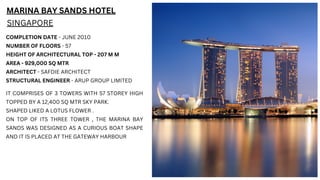
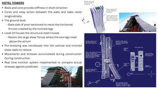
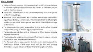
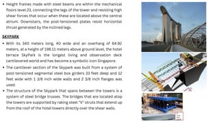
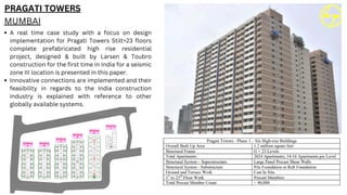
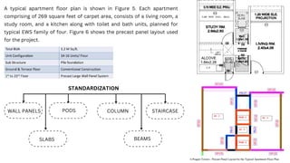
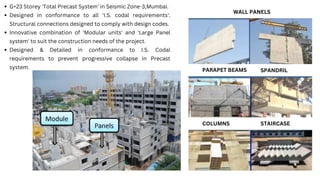
MARINA BAY SANDS HOTEL
SINGAPORE
COMPLETION DATE - JUNE 2010
NUMBER OF FLOORS - 57
HEIGHT OF ARCHITECTURAL TOP - 207 M M
AREA - 929,000 SQ MTR
ARCHITECT - SAFDIE ARCHITECT
STRUCTURAL ENGINEER - ARUP GROUP LIMITED
IT COMPRISES OF 3 TOWERS WITH 57 STOREY HIGH
TOPPED BY A 12,400 SQ MTR SKY PARK.
SHAPED LIKED A LOTUS FLOWER .
ON TOP OF ITS THREE TOWER , THE MARINA BAY
SANDS WAS DESIGNED AS A CURIOUS BOAT SHAPE
AND IT IS PLACED AT THE GATEWAY HARBOUR
Built on reclaimed land.
Layers:
Deepest layer is stiff-to-hard Old Alluvium (OA)
1.
Middle layer (5m- 35m thick) is Kallang Formation made of deep
soft clay marine deposits with some firm clay andmedium dense
sand of fluvial origin mixed in
2.
3.Top layer (12m-15m thick) is sand infill
Used a forest of barrettes and 1m-3m diameter bored piles
Average excavation depth was 20m
2.8 cubed Mm of fill and marine clay taken from site
Diaphragm walls used for minimum strutting
5 reinforced concrete cofferdams (- Circular)
- 2= 120m diameter
- 1=1 03 diameter
- Peanut shaped (twin-celled) = 75m diameter
Semi-circular - 65m radius
JET GROUTING IS USED DIAPHRAGRAM WALLS
FOUNDATION DESIGN
COFFERDAMS
HOTEL TOWERS
Reinforced concrete shear walls in the short direction
(East-West)
- Primary vertical and transverse structural system
Unlike other high-rise towers
-Primary lateral stability demands is NOT wind but is
gravity loads
-The curve creates overturning forces
Material selection was critical because
- Lateral load is permanent not transient like wind loads
Additional concrete core walls in each of the building legs
-Retrains the forces in the longitudinal directions
- Aids in preventing the out-of-plane buckling due
to the relatively narrow shear walls
Floor system
- 8 in flat slabs post-tensioned (max span of 10 m)
-Accommodates the 9'10 floor to floor height
Hotel tower flares out at 26 degrees
HOTEL TOWERS
Walls and core provide stiffness in short direction
Cores and sway action between the walls and slabs resist
longitudinally
The ground level
- Base slab of post-tensioned to resist the horizontal
thrusts created by the inclined legs
Level 23 houses the structural steel trusses
- Resists the large shear forces where the two legs meet
above the atrium
Pre-stressing was introduced into the vertical and inclined
shear walls to reduce
Movements and stresses accumulated during construction
During construction
Real time monitor system implemented to compare actual
stresses against predicted.
Walls reinforced concrete thickness ranging from 28 inches at its base
to 20 levels higher plants are found in the centers of 10 meters, within
each of the three towers.
Shear walls serve as vertical and transverse primary structural system
of the three buildings.
Additional cores also created with concrete walls are located in both
legs of each building containing the hotel longitudinally and helping to
prevent the exit plane buckling shear walls within relatively narrow legs
of the towers.
The requirement for such a restriction in the design after rigorous
analysis of buckling of the two legs soon established.
Flat post-tensioned slabs with a thickness of 22cm, extend directly
between shear walls.
This structural arrangement maximizes efficiency and creates a simple
solution slab floor that can be built quickly.
The flat slab scheme also provides flexibility in the distribution of the
hotel room, adapts to the height from floor to floor and building
flexibility in service delivery and coordination through each plant.
HOTEL TOWER
Height frames made with steel beams are within the mechanical
floors level 23, connecting the legs of the tower and resisting high
shear forces that occur when these are located above the central
atrium. Downstairs, the post-tensioned plates resist horizontal
thrust generated by the inclined legs.
SKYPARK
With its 340 meters long, 40 wide and an overhang of 64.92
meters, at a height of 198.11 meters above ground level, the hotel
terrace SkyPark is the longest living and observation deck
cantilevered world and has become a symbolic icon Singapore.
The cantilever section of the Skypark was built from a system of
post-tensioned segmental steel box girders 33 feet deep and 12
feet wide with 1 3/8 inch wide walls and 2 3/8 inch flanges was
used.
The structure of the Skypark that spans between the towers is a
system of steel bridge trusses. The bridges that are located atop
the towers are supported by raking steel "V" struts that extend up
from the roof of the hotel towers directly over the shear walls.
CONSTRUCTION SEQUENCE OF SKYWALK
14-main steel segments were prefabricated off site and lifted into place via
strand jacks
This method took cues from bridge building when lifting the segments into
place
Stranding jacking with hydraulic jacks were used to lift the box girders and
slide them into place.
The Cantilever was pre-assembled at grade to assure proper fit and then
disassembled and lifted into place and attached to a secondary beam at the
top of the hotel tower.
7000 tons of steel work was erected in 13 weeks to build the skypark
PRAGATI TOWERS
MUMBAI
A real time case study with a focus on design
implementation for Pragati Towers Stilt+23 floors
complete prefabricated high rise residential
project, designed & built by Larsen & Toubro
construction for the first time in India for a seismic
zone III location is presented in this paper.
Innovative connections are implemented and their
feasibility in regards to the India construction
industry is explained with reference to other
globally available systems.
A typical apartment floor plan is shown in Figure 5. Each apartment
comprising of 269 square feet of carpet area, consists of a living room, a
study room, and a kitchen along with toilet and bath units, planned for
typical EWS family of four. Figure 6 shows the precast panel layout used
for the project.
WALL PANELS
SLABS
PODS
STANDARDIZATION
BEAMS
COLUMN STAIRCASE
WALL PANELS
PARAPET BEAMS
COLUMNS STAIRCASE
SPANDRIL
G+23 Storey 'Total Precast System' in Seismic Zone-3,Mumbai.
Designed in conformance to all 'I.S. codal requirements'.
Structural connections designed to comply with design codes.
Innovative combination of 'Modular units' and 'Large Panel
system' to suit the construction needs of the project.
Designed & Detailed in conformance to I.S. Codal
requirements to prevent progressive collapse in Precast
system.

Prefabrication And Prestressing System .pdf

  • 2.
    MARINA BAY SANDSHOTEL SINGAPORE COMPLETION DATE - JUNE 2010 NUMBER OF FLOORS - 57 HEIGHT OF ARCHITECTURAL TOP - 207 M M AREA - 929,000 SQ MTR ARCHITECT - SAFDIE ARCHITECT STRUCTURAL ENGINEER - ARUP GROUP LIMITED IT COMPRISES OF 3 TOWERS WITH 57 STOREY HIGH TOPPED BY A 12,400 SQ MTR SKY PARK. SHAPED LIKED A LOTUS FLOWER . ON TOP OF ITS THREE TOWER , THE MARINA BAY SANDS WAS DESIGNED AS A CURIOUS BOAT SHAPE AND IT IS PLACED AT THE GATEWAY HARBOUR
  • 3.
    Built on reclaimedland. Layers: Deepest layer is stiff-to-hard Old Alluvium (OA) 1. Middle layer (5m- 35m thick) is Kallang Formation made of deep soft clay marine deposits with some firm clay andmedium dense sand of fluvial origin mixed in 2. 3.Top layer (12m-15m thick) is sand infill Used a forest of barrettes and 1m-3m diameter bored piles Average excavation depth was 20m 2.8 cubed Mm of fill and marine clay taken from site Diaphragm walls used for minimum strutting 5 reinforced concrete cofferdams (- Circular) - 2= 120m diameter - 1=1 03 diameter - Peanut shaped (twin-celled) = 75m diameter Semi-circular - 65m radius JET GROUTING IS USED DIAPHRAGRAM WALLS FOUNDATION DESIGN COFFERDAMS
  • 4.
    HOTEL TOWERS Reinforced concreteshear walls in the short direction (East-West) - Primary vertical and transverse structural system Unlike other high-rise towers -Primary lateral stability demands is NOT wind but is gravity loads -The curve creates overturning forces Material selection was critical because - Lateral load is permanent not transient like wind loads Additional concrete core walls in each of the building legs -Retrains the forces in the longitudinal directions - Aids in preventing the out-of-plane buckling due to the relatively narrow shear walls Floor system - 8 in flat slabs post-tensioned (max span of 10 m) -Accommodates the 9'10 floor to floor height Hotel tower flares out at 26 degrees
  • 5.
    HOTEL TOWERS Walls andcore provide stiffness in short direction Cores and sway action between the walls and slabs resist longitudinally The ground level - Base slab of post-tensioned to resist the horizontal thrusts created by the inclined legs Level 23 houses the structural steel trusses - Resists the large shear forces where the two legs meet above the atrium Pre-stressing was introduced into the vertical and inclined shear walls to reduce Movements and stresses accumulated during construction During construction Real time monitor system implemented to compare actual stresses against predicted.
  • 6.
    Walls reinforced concretethickness ranging from 28 inches at its base to 20 levels higher plants are found in the centers of 10 meters, within each of the three towers. Shear walls serve as vertical and transverse primary structural system of the three buildings. Additional cores also created with concrete walls are located in both legs of each building containing the hotel longitudinally and helping to prevent the exit plane buckling shear walls within relatively narrow legs of the towers. The requirement for such a restriction in the design after rigorous analysis of buckling of the two legs soon established. Flat post-tensioned slabs with a thickness of 22cm, extend directly between shear walls. This structural arrangement maximizes efficiency and creates a simple solution slab floor that can be built quickly. The flat slab scheme also provides flexibility in the distribution of the hotel room, adapts to the height from floor to floor and building flexibility in service delivery and coordination through each plant. HOTEL TOWER
  • 7.
    Height frames madewith steel beams are within the mechanical floors level 23, connecting the legs of the tower and resisting high shear forces that occur when these are located above the central atrium. Downstairs, the post-tensioned plates resist horizontal thrust generated by the inclined legs. SKYPARK With its 340 meters long, 40 wide and an overhang of 64.92 meters, at a height of 198.11 meters above ground level, the hotel terrace SkyPark is the longest living and observation deck cantilevered world and has become a symbolic icon Singapore. The cantilever section of the Skypark was built from a system of post-tensioned segmental steel box girders 33 feet deep and 12 feet wide with 1 3/8 inch wide walls and 2 3/8 inch flanges was used. The structure of the Skypark that spans between the towers is a system of steel bridge trusses. The bridges that are located atop the towers are supported by raking steel "V" struts that extend up from the roof of the hotel towers directly over the shear walls.
  • 8.
    CONSTRUCTION SEQUENCE OFSKYWALK 14-main steel segments were prefabricated off site and lifted into place via strand jacks This method took cues from bridge building when lifting the segments into place Stranding jacking with hydraulic jacks were used to lift the box girders and slide them into place. The Cantilever was pre-assembled at grade to assure proper fit and then disassembled and lifted into place and attached to a secondary beam at the top of the hotel tower. 7000 tons of steel work was erected in 13 weeks to build the skypark
  • 9.
    PRAGATI TOWERS MUMBAI A realtime case study with a focus on design implementation for Pragati Towers Stilt+23 floors complete prefabricated high rise residential project, designed & built by Larsen & Toubro construction for the first time in India for a seismic zone III location is presented in this paper. Innovative connections are implemented and their feasibility in regards to the India construction industry is explained with reference to other globally available systems.
  • 10.
    A typical apartmentfloor plan is shown in Figure 5. Each apartment comprising of 269 square feet of carpet area, consists of a living room, a study room, and a kitchen along with toilet and bath units, planned for typical EWS family of four. Figure 6 shows the precast panel layout used for the project. WALL PANELS SLABS PODS STANDARDIZATION BEAMS COLUMN STAIRCASE
  • 11.
    WALL PANELS PARAPET BEAMS COLUMNSSTAIRCASE SPANDRIL G+23 Storey 'Total Precast System' in Seismic Zone-3,Mumbai. Designed in conformance to all 'I.S. codal requirements'. Structural connections designed to comply with design codes. Innovative combination of 'Modular units' and 'Large Panel system' to suit the construction needs of the project. Designed & Detailed in conformance to I.S. Codal requirements to prevent progressive collapse in Precast system.